US4044783A - Label removal apparatus for container washing machines - Google Patents
Label removal apparatus for container washing machines Download PDFInfo
- Publication number
- US4044783A US4044783A US05/669,043 US66904376A US4044783A US 4044783 A US4044783 A US 4044783A US 66904376 A US66904376 A US 66904376A US 4044783 A US4044783 A US 4044783A
- Authority
- US
- United States
- Prior art keywords
- trough
- labels
- compartment
- washing solution
- transfer passage
- Prior art date
- Legal status (The legal status is an assumption and is not a legal conclusion. Google has not performed a legal analysis and makes no representation as to the accuracy of the status listed.)
- Expired - Lifetime
Links
- 238000005406 washing Methods 0.000 title claims abstract description 55
- 239000012530 fluid Substances 0.000 claims abstract description 17
- 239000000969 carrier Substances 0.000 claims description 12
- 238000011010 flushing procedure Methods 0.000 claims description 6
- 230000001174 ascending effect Effects 0.000 claims description 3
- 238000010380 label transfer Methods 0.000 claims 1
- 238000013508 migration Methods 0.000 claims 1
- 230000005012 migration Effects 0.000 claims 1
- 230000000630 rising effect Effects 0.000 claims 1
- 239000003518 caustics Substances 0.000 description 13
- 239000000853 adhesive Substances 0.000 description 4
- 230000001070 adhesive effect Effects 0.000 description 4
- 230000005484 gravity Effects 0.000 description 4
- 238000009825 accumulation Methods 0.000 description 3
- 230000000694 effects Effects 0.000 description 3
- 239000000463 material Substances 0.000 description 2
- 230000009471 action Effects 0.000 description 1
- 238000004140 cleaning Methods 0.000 description 1
- 230000006872 improvement Effects 0.000 description 1
- 230000007246 mechanism Effects 0.000 description 1
- 230000004048 modification Effects 0.000 description 1
- 238000012986 modification Methods 0.000 description 1
- 239000010813 municipal solid waste Substances 0.000 description 1
- 238000004513 sizing Methods 0.000 description 1
- 230000001954 sterilising effect Effects 0.000 description 1
- 230000004936 stimulating effect Effects 0.000 description 1
- 230000000638 stimulation Effects 0.000 description 1
- 230000001629 suppression Effects 0.000 description 1
- 239000000725 suspension Substances 0.000 description 1
Images
Classifications
-
- B—PERFORMING OPERATIONS; TRANSPORTING
- B08—CLEANING
- B08B—CLEANING IN GENERAL; PREVENTION OF FOULING IN GENERAL
- B08B3/00—Cleaning by methods involving the use or presence of liquid or steam
- B08B3/04—Cleaning involving contact with liquid
- B08B3/10—Cleaning involving contact with liquid with additional treatment of the liquid or of the object being cleaned, e.g. by heat, by electricity or by vibration
- B08B3/14—Removing waste, e.g. labels, from cleaning liquid
-
- B—PERFORMING OPERATIONS; TRANSPORTING
- B08—CLEANING
- B08B—CLEANING IN GENERAL; PREVENTION OF FOULING IN GENERAL
- B08B9/00—Cleaning hollow articles by methods or apparatus specially adapted thereto
- B08B9/08—Cleaning containers, e.g. tanks
- B08B9/083—Removing scrap from containers, e.g. removing labels
Definitions
- This invention relates to label removal apparatus for container washing machines, and particularly to such apparatus for handling labels normally pasted or glued on containers and which must be removed before reuse of the containers.
- the present invention is an improvement over container washing apparatus earlier disclosed in U.S. application Ser. No. 605,279, filed Aug. 18, 1975, and assigned in common with this application.
- Washing apparatus having known characteristics is disclosed in U.S. Pat. No. 3,162,204, issued Dec. 22, 1964, and assigned in common with this application.
- the apparatus conducted containers through several compartments containing hot caustic solution which penetrated the labels and the adhesive and caused the labels to become detached.
- That apparatus provided one or more troughs, each within the path of travel of the container carriers, for the purpose of accumulating the majority of detached labels and reducing the quantity of lables settling on the bottom of the compartments.
- Forced fluid circulating means provided in the compartment bottoms and in the troughs operated substantially continuously to remove the accumulation of labels before they could settle and pack, and become difficult to remove.
- the present washing apparatus is principally adapted for use in connection with the washing of containers for reuse, and wherein such containers brought to the washer are found to be carrying paper or metallic label material that is applied by a suitable adhesive. It is normal in washing apparatus of this character to insert the containers into individual pockets, which pockets are arranged in carriers that may be 40 to 60 pockets wide.
- the containers are continuously moved through several compartments containing hot caustic solution which is intended to remove foreign matter from the interior as well as to penetrate the label material so as to soften the adhesive and thereby cause the labels to become detached.
- the detached labels are permitted to exit from the carrier pockets as soon as possible and descend toward a unique arrangement of collecting means above the bottom of the compartments where fluid jets become useful in causing the descending labels to be propelled toward outlets.
- a difficulty with the operation of prior container washing apparatus is that the specific gravity of the labels after being subjected to the caustic solution very nearly equals the specific gravity of the washing solution itself. Since the specific gravity of the labels and the washing solution is nearly equal, the labels have a tendency to float or become quite boyant, thereby making the labels particularly sensitive to very low velocity movement of or turbulence in the washing solution. In the operation of many container washing machine, labels have been found to move in uncontrolled patterns and move into areas where they can be reapplied to the containers. That problem is overcome in the manner herein disclosed.
- Yet another object of the present invention is to provide means working in cooperation with fluid flow directing jets to cause label travel into areas of the compartments where confining means can prevent the labels floating into unwanted areas and can suppress turbulence of the washing solution.
- the container washing apparatus is divided into a plurality of compartments containing means which act as baffles, such that as the labels soften and are flushed from the containers they are caused to move into spaces where the baffles and fluid flow directing nozzles cooperate to cause the labels to move in a controlled pattern which is ultimately effective to direct the labels toward suction outlets.
- baffles and fluid circulating nozzles functions so as not to upset the orderly descent of detached labels from the upper areas of the compartments, as misdirected fluid flow and eddy currents set up thereby can result in propelling labels in unwanted directions to positions where they can become plastered on the carrier pockets and containers and be transported into compartments of the apparatus where the labels are distinctly not wanted.
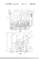
- FIG. 1 is a side elevational view of so much of the container washing apparatus and fluid circulating system as will serve to convey an understanding of the present invention
- FIG. 2 is a fragmentary perspective view of an exterior portion of the washing apparatus shown in FIG. 1 particularly showing a transfer passage for moving labels from a higher accumulating zone to a lower zone;
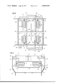
- FIG. 3 is a fragmentary plan view, partly in section, showing a typical trough accumulating zone seen at line 3--3 in FIG. 1;
- FIG. 4 is a fragmentary view, partly in section, showing a typical baffle assembly seen at line 4--4 in FIG. 1;
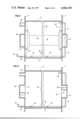
- FIG. 5 is a further fragmentary plan view, partly in section, of a baffle assembly for label collecting and control of movement to a discharge zone seen at line 5--5 in FIG. 1;
- FIG. 6 is a further fragmentary plan view, partly in section, of the bottom discharge zone seen at line 6--6 in FIG. 1;
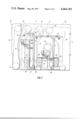
- FIG. 7 is a fragmentary side view of the side opposite to FIG. 1 showing the fluid circulating system associated with that side of the machine.
- the general exterior view of the container washer 10 is seen in fragmentary side elevation in FIG. 1 with the container infeed end at the right, and the opposite side is seen in FIG. 7 with the infeed at the left.
- the washer apparatus is enclosed between elongated side walls 11, while individual compartments A and B are separated by walls which are shown in broken line at 12, 13 and 14.
- a conveyor mechanism is directed through the apparatus in an endless manner on appropriate sprockets 15 carried by the side walls 11 and which support and drive the conveyor chain depicted by its pitch line 16.
- the chain 16 is spaced apart within the width of the side walls 11 as is usual in this apparatus.
- the carriers (FIG. 3) for the containers are elongated frames 17 extending between the chain 16 and each frame is provided with open-ended pockets 18 for the containers.
- the containers are usually fed into the pockets open end first.
- washing solution which may be hot caustic of a strength to penetrate the dirt and trash inside and to loosen the adhesive used to apply the labels to the exterior, thereby cleaning and sterilizing the containers at the same time.
- the containers enter the first shown compartment A from the open top formed between the side walls 11 and the transverse walls 12 and 13.
- the path of the conveyor chain 16 is defined by tracks 19 (FIGS. 2 and 3) which have a path matching the contour of means retaining the containers in the carriers, such as spaced bars or, or as shown, guide sheets 20.
- the sheets 20 extend to a bottom return loop which forms a trough 21 inside the descending and the ascending portions of the sheets (FIGS. 2 and 3).
- the guide sheets separate the trough and the space above it from the space in the compartment A on the outside of the sheet.
- the carriers 17 leave the first compartment A and traverses the next upper sprocket 15 to enter compartment B from its open top over the wall 13.
- This latter compartment is formed between the transverse walls 13 and 14 and due to the intermediate sprocket 22 being disposed below the upper sprockets 15, an intermediate low wall 23 is located under the sprocket 22 for a purpose later to be noted.
- the conveyor chain 16 in compartment B follows a track (not shown) which has the same contour as the guide sheets 24, although bars may be employed as noted above.
- the sheets 24 are directed into a first loop trough 25 ahead of the sprocket 22 and a second loop trough 26 behind sprocket 22, all as indicated in FIGS. 1 and 7.
- FIGS. 2 and 3 it can be seen that the opposite side walls 11 support projecting transfer passage forming means 28 each of which is formed as a rectangular box having a tapered lower portion 29 equipped with an access opening covered by a removal manhole cover 30.
- the transfer passages are associated with the several troughs 21, 25 and 26 (FIGS. 1 and 7) and a description of one thereof is believed to be sufficient for an understanding of all.
- the opposite ends of the trough 21 are open into the upper portion of the transfer passage 28 through a semicircular opening 31 formed in the side walls 11.
- the lower portion 29 of each transfer passage opens into the bottom of compartment A through a rectangular opening 32 (FIG. 6).
- the path of travel of the conveyor chains 16 follows the fixed track 19 so that, as shown in FIGS. 3 and 4, the containers pass around the curved underside of the trough 21.
- the right hand carrier 17 of FIG. 3 is descending while the left hand carrier 17 is ascending.
- the labels are flushed from the carriers 17 by a flushing nozzle device 33 supplied from a conduit 34 (FIG. 7).
- the flushing nozzle 33 is part of apparatus described and claimed in said co-pending application Ser. No. 605,279, filed Aug. 18, 1975, and having a common assignee with the present application.
- the nozzle device 33 causes labels to be flushed off of the containers and out of the carriers 17 into the space (FIGS. 1 and 7) between the guide means 20.
- the detaching labels are directed to fall into the trough 21 by the guide means 20, thereby not dispersing throughout the compartment A.
- the transfer passages 28 permit communication between the opposite ends of the trough 21 and a bottom space 35 to which the lower openings 32 of the transfer passages open.
- an assembly of baffles which, as seen best in FIG. 5, comprise longitudinal baffle plates 36 which extend between the side walls 11 and end baffle plates 37 which extend parallel to the side walls 11 and abut with the ends of the baffle plates 36.
- the several baffle plates are secured so as to slant downwardly toward a central opening 38 spaced below the trough 21 and in position to permit the descent of labels that may be late in detaching after the carriers 17 pass below the trough 21 (FIG. 4).
- the deflector plates 43 extend downwardly so that the fins 43A at the lower ends thereof begin substantially at the level with the upper margin of the openings 32 into the bottom space 35. This positioning and sizing of the deflector plates 43 is critical to the non-turbulent flow of labels and greatly improves the ability to cause the labels to flow into the bottom space 35 and remain below the baffle plates 36 and 37. While not specifically shown, the portion of the fins 43A which pass adjacent the removable manhole covers 30 can be attached to the covers so that on cover removal that portion will be removed to not obstruct entry, when necessary, of a service person.
- a second set of nozzles is provided in the bottom space 35 for maintaining a horizontal circular movement of the labels toward an outlet fitting 44.
- This set of nozzles includes a first pair 45 depending from and supplied by a common pipe 46 which extends along side the transverse wall 12 of compartment A. Pipe 46 passes through the side wall 11 to an exterior pipe 47 which extends under the transfer passage 28 and reenters the space 35 adjacent wall 13 where it connects with a single nozzle 48.
- the fluid supplying all of the nozzles shown in FIG. 3 is obtained from a separator device 50 (FIG. 1) which has an inlet 51 connected by conduit 52 to branch conduits 53 which are connected respectively to the outlet 44 from the bottom of compartment A, as well as outlets 44A from the bottom of compartment B on opposite sides of the intermediate wall 23.
- Each of the branch conduits 53 is provided with a control valve 54 so that the removal of labels may be alternately effected through the branch conduits 53. This alternation can be coordinated with the rate of label accumulation in the bottom of the compartments A and B.
- the separator device 50 is shown and described in U.S. Pat. No.
- FIG. 7 it can be seen that the supply pipe 34 for the flushing nozzle device 33 is connected to pump 61 driven by motor 62, and the pump 61 has its suction conduit 63 connected into the outlet box 64 associated with a rotary screen 65 which has been shown and described in the aforementioned co-pending application, Ser. No. 605,279.
- the outlet of pump 66 is directed by conduit 71 to conduits 72 and 73 respectively associated with flushing nozzle devices 74 and 75.
- a first branch conduit 76 from the main conduit 71 is connected to nozzles in the trough 26 which while not shown are equivalent to the foregoing described nozzles 40 and 42 shown in FIG. 3.
- a second branch conduit 77 from conduit 71 is connected to nozzles associated with the trough 25, such nozzles not being specifically shown or described but are equivalent to nozzles 40 and 42 seen in FIG. 3.
- FIG. 1 shows that the nozzle means for the bottom spaces below troughs 35 and 26 in compartment B are connected to branch pipes 78.
- transfer passages 28 have the width as shown in FIGS. 2 and 6, it is within the scope of the passage size to make them wider so that the opening 32 into the bottom of the compartment A is extended closer to the transverse wall 12 so that the deflector fin 43A can be moved into the plane of the deflector 43 and act to direct the flow of fluid and labels further into the corner below the baffles 36 and 37 where the horizontal circulating effect of the nozzles 45 will have even more effect to prevent the labels from reaching the opening 38 (FIG. 5) and possibly being caused to rise through that opening.
- the foregoing description has set forth the characteristics of label removing apparatus for washing machines for containers bearing removable labels, and has particularly set forth means for removing the detached labels from the machine by the circulation of the caustic washing solution internally of the washing machine and externally thereof in association with means for separating the labels from the caustic washing solution prior to is reuse.
- the label removal apparatus is associated with one or more compartments in the washing machine and is operatively disposed in an upper label collecting trough and in a lower label collecting space at the bottom of the compartment so that the action of washing solution flow directing nozzles can effect transfer of the accumulating labels from the trough to the compartment between space and then to the exterior of the washing machine.
Landscapes
- Engineering & Computer Science (AREA)
- Mechanical Engineering (AREA)
- Cleaning In General (AREA)
- Cleaning By Liquid Or Steam (AREA)
Priority Applications (8)
| Application Number | Priority Date | Filing Date | Title |
|---|---|---|---|
| US05/669,043 US4044783A (en) | 1976-03-22 | 1976-03-22 | Label removal apparatus for container washing machines |
| CA268,934A CA1056698A (en) | 1976-03-22 | 1976-12-30 | Label removing apparatus |
| GB54371/76A GB1521011A (en) | 1976-03-22 | 1976-12-30 | Label removal apparatus |
| DE19772702916 DE2702916A1 (de) | 1976-03-22 | 1977-01-21 | Vorrichtung zum entfernen von etiketten |
| BE1007900A BE850711A (fr) | 1976-03-22 | 1977-01-25 | Appareil d'enlevement d'etiquettes pour machine a laver des recipients |
| IT47782/77A IT1115811B (it) | 1976-03-22 | 1977-01-25 | Apparecchio per togliere etichette |
| FR7702385A FR2345232A1 (fr) | 1976-03-22 | 1977-01-28 | Appareil d'enlevement d'etiquettes pour machine a laver des recipients |
| JP2257877A JPS52116381A (en) | 1976-03-22 | 1977-03-02 | Label removing apparatus |
Applications Claiming Priority (1)
| Application Number | Priority Date | Filing Date | Title |
|---|---|---|---|
| US05/669,043 US4044783A (en) | 1976-03-22 | 1976-03-22 | Label removal apparatus for container washing machines |
Publications (1)
| Publication Number | Publication Date |
|---|---|
| US4044783A true US4044783A (en) | 1977-08-30 |
Family
ID=24684790
Family Applications (1)
| Application Number | Title | Priority Date | Filing Date |
|---|---|---|---|
| US05/669,043 Expired - Lifetime US4044783A (en) | 1976-03-22 | 1976-03-22 | Label removal apparatus for container washing machines |
Country Status (8)
| Country | Link |
|---|---|
| US (1) | US4044783A (it) |
| JP (1) | JPS52116381A (it) |
| BE (1) | BE850711A (it) |
| CA (1) | CA1056698A (it) |
| DE (1) | DE2702916A1 (it) |
| FR (1) | FR2345232A1 (it) |
| GB (1) | GB1521011A (it) |
| IT (1) | IT1115811B (it) |
Cited By (2)
| Publication number | Priority date | Publication date | Assignee | Title |
|---|---|---|---|---|
| US20050210871A1 (en) * | 2004-03-27 | 2005-09-29 | Cnh America Llc | Work vehicle hydraulic system |
| US11358077B2 (en) * | 2017-03-31 | 2022-06-14 | Krones Ag | Bottle-processing machine and method for cleaning the pump/nozzle protector of the bottle-processing machine |
Families Citing this family (3)
| Publication number | Priority date | Publication date | Assignee | Title |
|---|---|---|---|---|
| DE3135339C2 (de) * | 1981-09-07 | 1986-10-09 | Seitz Enzinger Noll Maschinenbau Ag, 6800 Mannheim | Maschine zum Waschen von Flaschen und Entfernen von Etiketten |
| DE102005026080B4 (de) * | 2005-06-07 | 2007-06-06 | Khs Ag | Flaschenreinigungsmaschine |
| CN112517487B (zh) * | 2020-10-30 | 2022-09-13 | 深圳博尔新材料技术有限公司 | 一种变压器加工用铜排定位清洗装置 |
Citations (3)
| Publication number | Priority date | Publication date | Assignee | Title |
|---|---|---|---|---|
| FR1090784A (fr) * | 1953-10-24 | 1955-04-04 | Riomilex | Procédé et machines de nettoyage de récipients tels que bouteilles portant des étiquettes |
| US3162204A (en) * | 1963-04-29 | 1964-12-22 | Barry Wehmiller Mach Co | Apparatus for removing labels from bottle washers |
| US3868960A (en) * | 1971-09-16 | 1975-03-04 | Anthony Raymond Cove | Machines for washing bottles and like containers and removing labels therefrom |
-
1976
- 1976-03-22 US US05/669,043 patent/US4044783A/en not_active Expired - Lifetime
- 1976-12-30 GB GB54371/76A patent/GB1521011A/en not_active Expired
- 1976-12-30 CA CA268,934A patent/CA1056698A/en not_active Expired
-
1977
- 1977-01-21 DE DE19772702916 patent/DE2702916A1/de not_active Withdrawn
- 1977-01-25 BE BE1007900A patent/BE850711A/xx unknown
- 1977-01-25 IT IT47782/77A patent/IT1115811B/it active
- 1977-01-28 FR FR7702385A patent/FR2345232A1/fr not_active Withdrawn
- 1977-03-02 JP JP2257877A patent/JPS52116381A/ja active Pending
Patent Citations (3)
| Publication number | Priority date | Publication date | Assignee | Title |
|---|---|---|---|---|
| FR1090784A (fr) * | 1953-10-24 | 1955-04-04 | Riomilex | Procédé et machines de nettoyage de récipients tels que bouteilles portant des étiquettes |
| US3162204A (en) * | 1963-04-29 | 1964-12-22 | Barry Wehmiller Mach Co | Apparatus for removing labels from bottle washers |
| US3868960A (en) * | 1971-09-16 | 1975-03-04 | Anthony Raymond Cove | Machines for washing bottles and like containers and removing labels therefrom |
Cited By (2)
| Publication number | Priority date | Publication date | Assignee | Title |
|---|---|---|---|---|
| US20050210871A1 (en) * | 2004-03-27 | 2005-09-29 | Cnh America Llc | Work vehicle hydraulic system |
| US11358077B2 (en) * | 2017-03-31 | 2022-06-14 | Krones Ag | Bottle-processing machine and method for cleaning the pump/nozzle protector of the bottle-processing machine |
Also Published As
| Publication number | Publication date |
|---|---|
| BE850711A (fr) | 1977-07-25 |
| IT1115811B (it) | 1986-02-10 |
| FR2345232A1 (fr) | 1977-10-21 |
| DE2702916A1 (de) | 1977-10-06 |
| JPS52116381A (en) | 1977-09-29 |
| GB1521011A (en) | 1978-08-09 |
| CA1056698A (en) | 1979-06-19 |
Similar Documents
| Publication | Publication Date | Title |
|---|---|---|
| EP1256417B1 (en) | Chip discharge conveyor system | |
| JP3851694B2 (ja) | 冷却潤滑剤の浄化装置 | |
| US2885080A (en) | Waste water renovator | |
| US5624579A (en) | Method of simultaneously indexing permanent and disposable filter media in a vacuum filter apparatus | |
| US4417541A (en) | Apparatus for spraying workpieces and intercepting overspray | |
| US4061152A (en) | Container washing apparatus | |
| US2694466A (en) | Paint spray eliminator | |
| KR860008340A (ko) | 폐지로부터의 잉크 제거방법 및 장치 | |
| DE310161T1 (de) | Verfahren und vorrichtung zum wegfuehren des staubs der beim loskreppen einer papierbahn freigemacht wird. | |
| JPS62114677A (ja) | ペイントスプレブ−ス | |
| US3752314A (en) | Flume water recycling apparatus | |
| US4044783A (en) | Label removal apparatus for container washing machines | |
| JPH0733235A (ja) | シュラウド | |
| JPS59145011A (ja) | 空気吸込装置付ベルト形フイルタ | |
| US3946750A (en) | Label remover for bottle washing machine | |
| GB1046814A (en) | Method and apparatus for removing labels from container washers | |
| JPH0568920A (ja) | 簡易塗装ブース | |
| US5865903A (en) | System and method for removing liquid applied to hollow containers | |
| US4693836A (en) | Filter apparatus with bypass prevention | |
| US3717255A (en) | Liquid clarification unit | |
| US2718966A (en) | Hydraulic classification method and apparatus | |
| US4041963A (en) | Container washer apparatus | |
| US2667881A (en) | Apparatus for draining and washing granular material | |
| EP0676985B1 (en) | Device and method for removing liquid on a gauze conveyor | |
| US3028962A (en) | Sink and float separation apparatus |
Legal Events
| Date | Code | Title | Description |
|---|---|---|---|
| AS | Assignment |
Owner name: CITICORP INDUSTRIAL CREDIT, INC., 200 S. WACKER, C Free format text: SECURITY INTEREST;ASSIGNOR:BARRY-WEHMILLER COMPANY A MO CORP;REEL/FRAME:004302/0831 Effective date: 19840724 |
|
| AS | Assignment |
Owner name: BARRY-WEHMILLER COMPANY (THE "COMPANY") Free format text: RELEASED BY SECURED PARTY;ASSIGNOR:CITICORP INDUSTRIAL CREDIT, INC.;REEL/FRAME:004673/0849 Effective date: 19870126 |