US4004671A - Wire matrix print head - Google Patents
Wire matrix print head Download PDFInfo
- Publication number
- US4004671A US4004671A US05/532,870 US53287074A US4004671A US 4004671 A US4004671 A US 4004671A US 53287074 A US53287074 A US 53287074A US 4004671 A US4004671 A US 4004671A
- Authority
- US
- United States
- Prior art keywords
- wire
- wires
- print wires
- along
- Prior art date
- Legal status (The legal status is an assumption and is not a legal conclusion. Google has not performed a legal analysis and makes no representation as to the accuracy of the status listed.)
- Expired - Lifetime
Links
Images


Classifications
-
- B—PERFORMING OPERATIONS; TRANSPORTING
- B41—PRINTING; LINING MACHINES; TYPEWRITERS; STAMPS
- B41J—TYPEWRITERS; SELECTIVE PRINTING MECHANISMS, i.e. MECHANISMS PRINTING OTHERWISE THAN FROM A FORME; CORRECTION OF TYPOGRAPHICAL ERRORS
- B41J2/00—Typewriters or selective printing mechanisms characterised by the printing or marking process for which they are designed
- B41J2/22—Typewriters or selective printing mechanisms characterised by the printing or marking process for which they are designed characterised by selective application of impact or pressure on a printing material or impression-transfer material
- B41J2/23—Typewriters or selective printing mechanisms characterised by the printing or marking process for which they are designed characterised by selective application of impact or pressure on a printing material or impression-transfer material using print wires
- B41J2/235—Print head assemblies
- B41J2/25—Print wires
- B41J2/255—Arrangement of the print ends of the wires
-
- B—PERFORMING OPERATIONS; TRANSPORTING
- B41—PRINTING; LINING MACHINES; TYPEWRITERS; STAMPS
- B41J—TYPEWRITERS; SELECTIVE PRINTING MECHANISMS, i.e. MECHANISMS PRINTING OTHERWISE THAN FROM A FORME; CORRECTION OF TYPOGRAPHICAL ERRORS
- B41J2/00—Typewriters or selective printing mechanisms characterised by the printing or marking process for which they are designed
- B41J2/22—Typewriters or selective printing mechanisms characterised by the printing or marking process for which they are designed characterised by selective application of impact or pressure on a printing material or impression-transfer material
- B41J2/23—Typewriters or selective printing mechanisms characterised by the printing or marking process for which they are designed characterised by selective application of impact or pressure on a printing material or impression-transfer material using print wires
- B41J2/235—Print head assemblies
- B41J2/265—Guides for print wires
-
- B—PERFORMING OPERATIONS; TRANSPORTING
- B41—PRINTING; LINING MACHINES; TYPEWRITERS; STAMPS
- B41J—TYPEWRITERS; SELECTIVE PRINTING MECHANISMS, i.e. MECHANISMS PRINTING OTHERWISE THAN FROM A FORME; CORRECTION OF TYPOGRAPHICAL ERRORS
- B41J2/00—Typewriters or selective printing mechanisms characterised by the printing or marking process for which they are designed
- B41J2/22—Typewriters or selective printing mechanisms characterised by the printing or marking process for which they are designed characterised by selective application of impact or pressure on a printing material or impression-transfer material
- B41J2/23—Typewriters or selective printing mechanisms characterised by the printing or marking process for which they are designed characterised by selective application of impact or pressure on a printing material or impression-transfer material using print wires
- B41J2/27—Actuators for print wires
- B41J2/285—Actuators for print wires of plunger type
Definitions
- This invention relates generally to matrix printer apparatus and more particularly relates to a novel and improved wire matrix print head for a wire printer including the wire guide body and solenoid actuator construction and arrangement with respect to the body.
- the print wires In printing characters or symbols with a matrix print head, customarily the print wires have their leading ends disposed in confronting relation to the record of print medium so that as the print head is advanced across the page selected wires are actuated to drive their leading ends into the print medium to form a series of dots which make up each character or symbol.
- the print wires must be actuated several times in forming each character or symbol and, since they are driven along their lengths are highly subject to wear, misalignment and uneven impressions as the print head is advanced across the page.
- the leading ends of the print wires are arranged in closely spaced relation to one another and necessarily must diverge rearwardly away from the closely spaced leading ends in order to afford sufficient spacing for insertion of the trailing end of each print wire in an actuator.
- the actuators are of the solenoid or electromagnetic type, and the trailing end of each print wire is affixed to the armature so that when the armature is energized it will cause the print wire to advance forwardly in driving its leading end into contact with the print medium.
- the print wires must be of sufficient length to permit gradual divergency away from their leading ends to a point which will afford sufficient spacing between the electromagnetic actuators.
- a further object of the present invention is to provide for a novel and improved, simplified and compact means for mounting print wires in a matrix print head for selective actuation of each wire in forming characters comprised of a series of dots; and wherein the wires are supported in such a way as to minimize frictional engagement and permit open support of the wires along the greater portion of their length.
- a further object of the present invention is to provide in a wire matrix print head for improved guide means to support each wire on its elastic curve and with each print wire diverging rearwardly through planes located at equally displaced angles with respect to the plane of adjacent print wires whereby to permit the most compact and lightweight mounting possible for the print wires combined with maximum efficiency, dependability and life.
- a still further object of the present invention is to provide for a wire matrix print head assembly characterized by its versatility and conformability for use at different speeds in various different printing applications heretofore not considered feasible for matrix printers.
- a wire matrix print head has been devised for dot or wire matrix printers in which the print wires are disposed and guided for movement in a generally conical, slotted wire guide body which converges forwardly into a hollow head and terminates in a bearing portion at its leading end, the bearing portion defining a series of vertically aligned closely spaced openings for reception of the leading ends of the print wires.
- the trailing ends of the print wires are mounted in electromagnetic actuators which are attached to the wire guide body so that the trailing ends form the corners of an unequal-sided polygon in an imaginary plane passing transversely of the direction of movement of the leading ends of the print wires into the print medium.
- the wire guide body is provided with arcuate, open slots for reception of the greater length of the print wires as they are caused to converge forwardly from the trailing ends through open support means formed in the hollow head and at each point along the length of the print wires between their attachment to the electromagnetic actuators and their passage through the open support in the head, the wires would form the corners of a polygon in an imaginary plane passing through the print wires transversely of or normal to their direction of movement into the print medium.
- the geometrical relationship between the print wires is a result of their extension in different radial directions away from their leading ends along equal radii of curvature and at equally displaced included angles between adjacent print wires. In this way, each print wire will respond in like manner in being driven forwardly by its electromagnetic actuator into the paper so as to assure that the leading ends will make even impressions or dots on the print medium.
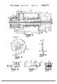
- FIG. 1 is a top plan view of a preferred form of print head assembly in accordance with the present invention.
- FIG. 2 is a side view in elevation of the assembly shown in FIG. 1.
- FIG. 3 is an enlarged vertical cross-section view of one of the solenoid actuators.
- FIG. 4 is a detail end view of the retainer member for a plurality of solenoid actuators.
- FIG. 5 is a cross-sectional view taken about lines 5--5 of FIG. 4.
- FIG. 6 is an enlarged view of the forward head portion of the print head assembly.
- FIG. 7 is a view from the rearward end of the head portion shown in FIG. 6.
- FIG. 8 is a front view of the opposite end of the head portion shown in FIG. 6.
- FIG. 9 is an enlarged view in more detail of the conical body of the wire guide.
- FIG. 10 is an end view from the rear end of the wire guide body shown in FIG. 9 with the retainer plate shown in FIG. 4;
- FIG. 11 is an end view of the opposite end of the wire guide body shown in FIG. 9.
- FIGS. 1 and 2 there is illustrated in FIGS. 1 and 2 a preferred form of print head assembly 10 which is adapted to be incorporated for use in various wire matrix printer applications, such as, for example, a calculator printer of the type set forth and described in my copending application, Ser. No. 527,603, filed 27 Nov., 1974 and entitled SERIAL IMPACT CALCULATOR PRINTER.
- the print head assembly 10 is broadly comprised of a plurality of print wires 12 arranged for extension through a wire guide assembly 24 the trailing end of each print wire 12 being mounted in one of the solenoid actuators 14 so that when one of the actuators 14 is energized it is operative to drive its associated print wire through the wire guide assembly forwardly to impress a print ribbon R against a record or print medium, such as, an endless roll of paper represented at P which is advanced and supported by a platen, not shown.
- a record or print medium such as, an endless roll of paper represented at P which is advanced and supported by a platen, not shown.
- the print head assembly as described may be suitably mounted for translational movement across the paper or other print medium in various ways; and in the preferred embodiment as shown, the assembly is mounted on a head carrier 16 which includes a bore 17 for insertion of support shaft S, a slide projection 19 which is adapted to be inserted into a groove represented at G in the frame of the printer apparatus, and a stud 20 which is adapted for insertion in the groove G' of a drive roller R.
- rotation of drive roller R will through the helical groove G' impart translational movement to the stud 20 on the head carrier so that the print head assembly is caused to advance laterally across each line of a page for printing characters or symbols thereon.
- one or more selected print wires may be actuated at predetermined incremental positions as the print head assembly 10 is caused to advance across each line so that each character or symbol formed is comprised of a series of dots or impressions caused by driving of the print wires forwardly against the print medium.
- five print wires 12 are provided with their leading ends arranged in a single column as hereinafter described although it will become apparent that the principles of the present invention would equally apply to other selected numbers of print wires and whether or not the leading ends are arranged in single or multiple columns or in other alignments as well.
- a conical body 24 converges forwardly in a direction away from the solenoid actuators 14 to terminate in a forward, generally cylindrical terminal end 25.
- Open slots 26 are formed in the external surface of the conical body 24 at spaced circumferential intervals to extend the full length of the body and similarly to converge forwardly from the rearward end to the forward terminal end 25, as best seen from a consideration of FIGS. 1, 2 and 9 to 11.
- each slot 26 is of generally rectangular cross-section and has outwardly flared or beveled sides 28 which define an entrance into each slot, the slot itself generally conforming in width to the diameter or cross-sectional size of the print wire 12 seated therein.
- each slot varies in depth along its length, and each slot is of a slightly different depth to permit its respective print wire to be disposed to extend along its elastic curve, for example, as illustrated by the print wire 12 in FIG. 2.
- the wire guide body 24 preferably is affixed to the rearward end of the head carrier 16 by a downwardly projecting flange 30 which is affixed by a suitable fastener 32 to the body of the head carrier.
- a retainer plate 40 as shown in detail in FIGS. 4 and 5, includes a relatively flat central portion 41 and inclined outer circumferential retainer portions 42, the plate being connected to the mounting block 36 by insertion of the studs 34 and 35 into central keyways 43 and insertion of a fastening screw 44 through the keyway between the studs 34 and 35 and into threaded engagement with the bore 38 in the mounting block, as shown in FIG. 10.
- the mounting block additionally is provided with radially extending projections 45 at spaced circumferential intervals, and radial slots 46 are arranged at spaced circumferential intervals in the outer inclined portion 42 of the retainer plate so as to be located intermediately between the radial projections 45 when the retainer plate is properly aligned by the studs 34 and 35 and mounted in place on the mounting block by the screw 44.
- the radial slots 46 are each sized for insertion of the nose 48 of a solenoid actuator 14 with a central opening 49 in the nose which is adapted to receive the trailing end of a print wire 12 and is therefore coaxially aligned with the rearward direction of extension of each print wire 12 from its guide slot 26 in the wire guide body.
- each solenoid actuator is aligned with a respective guide slot and specifically with a print wire extending rearwardly away from the slot so as to fix the trailing ends of the print wires in predetermined relation to the desired line or radius of curvature of the print wires through the respective guide slots 26 in a manner to be hereinafter described in more detail.
- the forward cylindrical end 25 of the wire guide 24 is inserted into a counterbore formed in the rearward end of a hollow generally rectangular head or barrel portion 50, as shown in FIGS. 7 to 9, the head 50 having an inset portion 51 on its lower surface seated on and positively affixed to the forward end of the head carrier 16.
- a rear wall or plate 54 is mounted across the rearward end of the hollow head directly in front of the forward terminal end 25 and includes a five-sided opening 55 therein which has five internal side surfaces designated a, b, c, d and e, inclusive, which are aligned along the desired path of extension of the print wire 12.
- the forward end of the head 50 includes a forwardly tapered nose portion 56 with a circular opening 57 communicating with the hollow interior of the head and adapted to receive a circular bearing plate 58 in which are formed a series of vertically aligned, horizontally extending, closely spaced openings 59 to receive leading ends 12' of the print wires 12.
- an alignment block 60 is suspended from a cover plate 61 for downward extension into the hollow interior of the head, the block 60 provided with a vertical slot 62 aligned with the openings 59 in the bearing plate whereby to support and pre-align the print wires 12 for forward extension from the plate 54 into the bearing plate 58.
- the slot 62 causes the wires to converge into substantially parallel superimposed relation for continued horizontal extension through the openings 59.
- the actuator 14 as shown is seen to comprise an outer cylindrical housing 64 having the solid nose portion 48 inserted within the forward end of the housing and permanently affixed thereto.
- the nose has a circumferential groove 48' which is sized for insertion into one of the radial slots 46 on the retainer 40 as hereinbefore described with the central opening 49 aligned for insertion of the trailing end 12" of the print wire 12.
- a drive coil 65 is wound upon a bobbin or spool 66 which is placed in surrounding relation to a thin-walled copper tube 67.
- a front pole piece 68 is inserted into one end of the tube 67 and has an enlarged circular flange 69 which is interposed between the nose 48 and the spool 66, and a central bore 70 in the pole piece 68 is aligned with, but of reduced size with respect to, the central opening 49 in the nose.
- a second pole piece 72 is interposed between the spool 66 and end stop 74, the pole piece being of annular configuration and provided with an opening to permit rearward extension of lead wires 73 from the coil 65 to energize the coil from a suitable source of electricity, not shown.
- the end stop 74 is generally in the form of a plastic cup and has a rearwardly directed sleeve 75 which is sized to receive a return spring 76 in surrounding relation to armature 78, the latter provided with a washer 79 and another end step 80 to retain the return spring normally under compression between the stops 74 and 80.
- the sleeve 75 also prevents wire 73 from interfering with the spring 76, armature 78, washer 79, and end stop 80.
- the armature 78 is provided with an enlarged cylindrical portion 82 inserted through the rearward end of the copper tube 67 and a reduced cylindrical stem portion 84 projecting rearwardly through a central opening in the end stop 74 and beyond the rearward end of the housing 64.
- the rearward end of the housing includes an end wall 64' of limited extent to properly locate the elements as described between the end stop 74 and the front nose portion 48.
- the armature 78 is provided with a central bore 88 coaxially aligned with the central bore 70 in the pole piece 68 to receive the rearward extremity of the trailing end 12" of the print wire 12.
- the forward cylindrical portion 82 of the armatutre includes an external circumferential groove 89 directly opposite to the rearward extremity of the print wire to facilitate its positive attachment of the print wire to the armature by bending the wall of the bore 88 and the rearward extremity of the wire, as shown, in a direction transversely of the length of the wire. This may be suitably accomplished prior to its assembly within the housing by striking the armature at a point on the surface of the groove 89 to cause the inner wall of the bore as well as the end 12" of the wire 12 to be bent so as to prevent its accidental loosening or removal.
- the preferred form of print head assembly supports each print wire 12 so that its leading end 12' extends substantially along a straight line from the bearing plate 58 through the slot 62 in alignment block 60.
- Each wire then follows a curved line established by supporting it against a side surface of the opening 55, along the bottom of one of the slots 26 and affixing the outer trailing end 12" in one of the actuators 14 which is coaxially aligned with the rearward end of the respective slot 26.
- the cooperative disposition and relation between each actuator 14, slot 26 and side surface of opening 55 is such as to locate each respective print wire 12 on its elastic curve, as a result of which the force to deflect the leading end 12' is held to a minimum.
- the print wires have their leading ends 12' in vertically aligned relation as described; and to most effectively mount the individual wires 12 in the manner described, each wire is caused to diverge rearwardly both with respect to a center line extending through the path of travel of its leading end and with respect to each adjacent wire so that for a given size of actuator sufficient clearance is afforded between the trailing ends of the print wires for disposition of the actuators in juxtaposed relation to one another at the least possible distance, or length, from the leading ends of the print wires which is equally important in achieving minimal deflection of the leading ends of the print wires.
- the print head assembly is advanced laterally of the print medium in accordance with conventional practice and one or more actuators 14 are energized by energizing their drive coils 65 to simultaneously drive their actuators forwardly and cause the leading ends 12" to force the print ribbon R against the print medium P.
- the spacing of the print medium P in front of the leading ends 12' is less than the spacing between the armature 82 and front pole piece 68 so that the leading end 12' will strike the print medium before the armature 82 strikes the pole piece 68 in each forward stoke. Accordingly, when the coil 65 is deenergized the return spring 76 will cause the armature to be reversed and to pull the leading end of its associated print wire 12 rearwardly into the bearing plate 58 in preparation for the next print cycle.
Landscapes
- Impact Printers (AREA)
Priority Applications (11)
| Application Number | Priority Date | Filing Date | Title |
|---|---|---|---|
| US05/532,870 US4004671A (en) | 1974-12-16 | 1974-12-16 | Wire matrix print head |
| AR261628A AR205416A1 (es) | 1974-12-16 | 1975-01-01 | Conjunto de cabeza impresora de matriz de alambres |
| JP50136785A JPS5178431A (enExample) | 1974-12-16 | 1975-11-13 | |
| CA240,872A CA1054851A (en) | 1974-12-16 | 1975-12-02 | Wire matrix print head |
| GB50692/75A GB1529847A (en) | 1974-12-16 | 1975-12-10 | Printing apparatus |
| SE7514001A SE7514001L (sv) | 1974-12-16 | 1975-12-11 | Tryckningsanordning |
| BR7508268*A BR7508268A (pt) | 1974-12-16 | 1975-12-15 | Conjunto de cabeca de impressao de matriz de fio |
| AU87564/75A AU8756475A (en) | 1974-12-16 | 1975-12-15 | Printing apparatus |
| CH1620575A CH602349A5 (enExample) | 1974-12-16 | 1975-12-15 | |
| IT30301/75A IT1050782B (it) | 1974-12-16 | 1975-12-15 | Gruppo testa stampante a matrice di fili per stampa a matrice |
| FR7538518A FR2294851A1 (fr) | 1974-12-16 | 1975-12-16 | Ensemble de tete d'impression a matrice de points |
Applications Claiming Priority (1)
| Application Number | Priority Date | Filing Date | Title |
|---|---|---|---|
| US05/532,870 US4004671A (en) | 1974-12-16 | 1974-12-16 | Wire matrix print head |
Publications (1)
| Publication Number | Publication Date |
|---|---|
| US4004671A true US4004671A (en) | 1977-01-25 |
Family
ID=24123511
Family Applications (1)
| Application Number | Title | Priority Date | Filing Date |
|---|---|---|---|
| US05/532,870 Expired - Lifetime US4004671A (en) | 1974-12-16 | 1974-12-16 | Wire matrix print head |
Country Status (11)
| Country | Link |
|---|---|
| US (1) | US4004671A (enExample) |
| JP (1) | JPS5178431A (enExample) |
| AR (1) | AR205416A1 (enExample) |
| AU (1) | AU8756475A (enExample) |
| BR (1) | BR7508268A (enExample) |
| CA (1) | CA1054851A (enExample) |
| CH (1) | CH602349A5 (enExample) |
| FR (1) | FR2294851A1 (enExample) |
| GB (1) | GB1529847A (enExample) |
| IT (1) | IT1050782B (enExample) |
| SE (1) | SE7514001L (enExample) |
Cited By (14)
| Publication number | Priority date | Publication date | Assignee | Title |
|---|---|---|---|---|
| US4081067A (en) * | 1977-03-07 | 1978-03-28 | Ncr Corporation | Internal vibration dampening means for printing mechanism |
| DE2909552A1 (de) * | 1978-03-10 | 1979-09-20 | Dh Ass | Matrixdruckkopfanordnung |
| US4176976A (en) * | 1977-04-15 | 1979-12-04 | Triumph Werke Nurnberg A.G. | Mosaic printing head |
| US4185929A (en) * | 1978-03-10 | 1980-01-29 | Helmut Falk | Wire matrix print head assembly |
| US4211496A (en) * | 1979-01-29 | 1980-07-08 | Small Business Administration | Printing solenoid |
| US4218148A (en) * | 1976-01-05 | 1980-08-19 | Printer Associates | Matrix printing cell and head assembly |
| US4238160A (en) * | 1978-06-02 | 1980-12-09 | C. Itoh Electronics, Inc. | Media guide |
| US4242006A (en) * | 1978-06-02 | 1980-12-30 | C. Itoh Electronics, Inc. | Adjustable media advancement mechanism |
| US4242005A (en) * | 1978-06-02 | 1980-12-30 | C. Itoh Electronics, Inc. | Inked ribbon advance and reverse mechanism including a pawl having different size teeth |
| US4260271A (en) * | 1978-06-02 | 1981-04-07 | C. Itoh Electronics | Inked ribbon advancement mechanism |
| US4309116A (en) * | 1978-08-02 | 1982-01-05 | Star Seimitsu Kabushiki Kaisha | Print head assembly of wire dot matrix printer |
| US4350450A (en) * | 1979-10-02 | 1982-09-21 | U.S. Philips Corporation | Stylus printing head comprising electromagnets on resilient supports |
| US4386860A (en) * | 1981-03-13 | 1983-06-07 | Data Card Corporation | High speed label printer |
| US20040096367A1 (en) * | 2000-03-20 | 2004-05-20 | Perkinelmer Las, Inc. | Method and apparatus for producing compact microarrays |
Citations (10)
| Publication number | Priority date | Publication date | Assignee | Title |
|---|---|---|---|---|
| US2129065A (en) * | 1937-07-06 | 1938-09-06 | Joseph N Loop | Apparatus for printing characters |
| US2928338A (en) * | 1954-04-15 | 1960-03-15 | Burroughs Corp | Wire printing mechanism |
| US3333667A (en) * | 1965-12-09 | 1967-08-01 | Teletype Corp | Flexible wire guide cable |
| US3584575A (en) * | 1968-11-12 | 1971-06-15 | Johann Distl | Mosaic printing head and device for producing the same |
| US3592311A (en) * | 1968-10-02 | 1971-07-13 | Ibm | Wire printing head |
| US3627096A (en) * | 1969-04-25 | 1971-12-14 | Ibm | Wire printing method |
| US3672482A (en) * | 1970-08-31 | 1972-06-27 | Ibm | Wire matrix print head |
| US3795298A (en) * | 1972-05-30 | 1974-03-05 | An Control Inc Di | Wire matrix print head particularly for high speed printers |
| US3833105A (en) * | 1970-05-15 | 1974-09-03 | Centronics Data Computer | Printer head assembly |
| US3897865A (en) * | 1973-12-11 | 1975-08-05 | Ibm | Dot printing apparatus |
-
1974
- 1974-12-16 US US05/532,870 patent/US4004671A/en not_active Expired - Lifetime
-
1975
- 1975-01-01 AR AR261628A patent/AR205416A1/es active
- 1975-11-13 JP JP50136785A patent/JPS5178431A/ja active Pending
- 1975-12-02 CA CA240,872A patent/CA1054851A/en not_active Expired
- 1975-12-10 GB GB50692/75A patent/GB1529847A/en not_active Expired
- 1975-12-11 SE SE7514001A patent/SE7514001L/xx unknown
- 1975-12-15 AU AU87564/75A patent/AU8756475A/en not_active Expired
- 1975-12-15 CH CH1620575A patent/CH602349A5/xx not_active IP Right Cessation
- 1975-12-15 BR BR7508268*A patent/BR7508268A/pt unknown
- 1975-12-15 IT IT30301/75A patent/IT1050782B/it active
- 1975-12-16 FR FR7538518A patent/FR2294851A1/fr active Granted
Patent Citations (10)
| Publication number | Priority date | Publication date | Assignee | Title |
|---|---|---|---|---|
| US2129065A (en) * | 1937-07-06 | 1938-09-06 | Joseph N Loop | Apparatus for printing characters |
| US2928338A (en) * | 1954-04-15 | 1960-03-15 | Burroughs Corp | Wire printing mechanism |
| US3333667A (en) * | 1965-12-09 | 1967-08-01 | Teletype Corp | Flexible wire guide cable |
| US3592311A (en) * | 1968-10-02 | 1971-07-13 | Ibm | Wire printing head |
| US3584575A (en) * | 1968-11-12 | 1971-06-15 | Johann Distl | Mosaic printing head and device for producing the same |
| US3627096A (en) * | 1969-04-25 | 1971-12-14 | Ibm | Wire printing method |
| US3833105A (en) * | 1970-05-15 | 1974-09-03 | Centronics Data Computer | Printer head assembly |
| US3672482A (en) * | 1970-08-31 | 1972-06-27 | Ibm | Wire matrix print head |
| US3795298A (en) * | 1972-05-30 | 1974-03-05 | An Control Inc Di | Wire matrix print head particularly for high speed printers |
| US3897865A (en) * | 1973-12-11 | 1975-08-05 | Ibm | Dot printing apparatus |
Cited By (16)
| Publication number | Priority date | Publication date | Assignee | Title |
|---|---|---|---|---|
| US4218148A (en) * | 1976-01-05 | 1980-08-19 | Printer Associates | Matrix printing cell and head assembly |
| FR2383019A1 (fr) * | 1977-03-07 | 1978-10-06 | Ncr Co | Dispositif amortisseur pour appareil d'impression matricielle a fils |
| US4081067A (en) * | 1977-03-07 | 1978-03-28 | Ncr Corporation | Internal vibration dampening means for printing mechanism |
| US4176976A (en) * | 1977-04-15 | 1979-12-04 | Triumph Werke Nurnberg A.G. | Mosaic printing head |
| DE2909552A1 (de) * | 1978-03-10 | 1979-09-20 | Dh Ass | Matrixdruckkopfanordnung |
| WO1979000738A1 (en) * | 1978-03-10 | 1979-10-04 | Dh Ass | Matrix print head assembly |
| US4185929A (en) * | 1978-03-10 | 1980-01-29 | Helmut Falk | Wire matrix print head assembly |
| US4238160A (en) * | 1978-06-02 | 1980-12-09 | C. Itoh Electronics, Inc. | Media guide |
| US4242006A (en) * | 1978-06-02 | 1980-12-30 | C. Itoh Electronics, Inc. | Adjustable media advancement mechanism |
| US4242005A (en) * | 1978-06-02 | 1980-12-30 | C. Itoh Electronics, Inc. | Inked ribbon advance and reverse mechanism including a pawl having different size teeth |
| US4260271A (en) * | 1978-06-02 | 1981-04-07 | C. Itoh Electronics | Inked ribbon advancement mechanism |
| US4309116A (en) * | 1978-08-02 | 1982-01-05 | Star Seimitsu Kabushiki Kaisha | Print head assembly of wire dot matrix printer |
| US4211496A (en) * | 1979-01-29 | 1980-07-08 | Small Business Administration | Printing solenoid |
| US4350450A (en) * | 1979-10-02 | 1982-09-21 | U.S. Philips Corporation | Stylus printing head comprising electromagnets on resilient supports |
| US4386860A (en) * | 1981-03-13 | 1983-06-07 | Data Card Corporation | High speed label printer |
| US20040096367A1 (en) * | 2000-03-20 | 2004-05-20 | Perkinelmer Las, Inc. | Method and apparatus for producing compact microarrays |
Also Published As
| Publication number | Publication date |
|---|---|
| IT1050782B (it) | 1981-03-20 |
| CH602349A5 (enExample) | 1978-07-31 |
| CA1054851A (en) | 1979-05-22 |
| BR7508268A (pt) | 1976-09-08 |
| JPS5178431A (enExample) | 1976-07-08 |
| FR2294851A1 (fr) | 1976-07-16 |
| SE7514001L (sv) | 1976-06-17 |
| AR205416A1 (es) | 1976-04-30 |
| FR2294851B3 (enExample) | 1979-10-05 |
| GB1529847A (en) | 1978-10-25 |
| AU8756475A (en) | 1977-06-23 |
Similar Documents
| Publication | Publication Date | Title |
|---|---|---|
| US4004671A (en) | Wire matrix print head | |
| US3672482A (en) | Wire matrix print head | |
| US3897865A (en) | Dot printing apparatus | |
| JPS62246743A (ja) | マトリクスプリンタ | |
| US4140406A (en) | Dot matrix print head | |
| GB2059353A (en) | Dot printer head | |
| JPS6344551B2 (enExample) | ||
| US4240756A (en) | Optimized wire matrix impact print head | |
| US4437775A (en) | Dot printer head | |
| JP2791582B2 (ja) | モータ及びギヤ取付ブラケット | |
| US4236836A (en) | Dot impact printer and actuator therefor | |
| US3835975A (en) | Printer head assembly | |
| JPS604790B2 (ja) | ワイヤ・マトリックス・プリンタ用アクチュエ−タ | |
| US4279518A (en) | Dot matrix print head | |
| US4081067A (en) | Internal vibration dampening means for printing mechanism | |
| US4236842A (en) | Hammer support for rotary printing apparatus | |
| US4273452A (en) | Print head for a dot printer | |
| EP0114744B1 (en) | Dot printer head | |
| KR800000847B1 (ko) | 와이어 매트릭스(wire matrix)인자판 | |
| GB1582690A (en) | Printing apparatus | |
| US3314359A (en) | Actuating mechanism for printing hammers | |
| WO1989010841A1 (en) | Dot matrix print head assembly | |
| US3854564A (en) | Printing heads for printing machines | |
| GB1563779A (en) | Printing apparatus | |
| US4708501A (en) | Electromagnetic hammer printing device including a limited action spring force |
Legal Events
| Date | Code | Title | Description |
|---|---|---|---|
| STCF | Information on status: patent grant |
Free format text: PATENTED FILE - (OLD CASE ADDED FOR FILE TRACKING PURPOSES) |
|
| AS | Assignment |
Owner name: MICRO PERIPHERALS, INC., 15070 AVENUE OF SCIENCE, Free format text: ASSIGNMENT OF ASSIGNORS INTEREST.;ASSIGNOR:EATON CORPORATION, A CORP. OF OH.;REEL/FRAME:004942/0898 Effective date: 19880331 Owner name: MICRO PERIPHERALS, INC., A COMPANY OF UT,CALIFORNI Free format text: ASSIGNMENT OF ASSIGNORS INTEREST;ASSIGNOR:EATON CORPORATION, A CORP. OF OH.;REEL/FRAME:004942/0898 Effective date: 19880331 |