US3901068A - Device for determining the colloidal stability of a liquid - Google Patents
Device for determining the colloidal stability of a liquid Download PDFInfo
- Publication number
- US3901068A US3901068A US385242A US38524273A US3901068A US 3901068 A US3901068 A US 3901068A US 385242 A US385242 A US 385242A US 38524273 A US38524273 A US 38524273A US 3901068 A US3901068 A US 3901068A
- Authority
- US
- United States
- Prior art keywords
- liquid
- tank
- bottles
- chilling
- refrigerating
- Prior art date
- Legal status (The legal status is an assumption and is not a legal conclusion. Google has not performed a legal analysis and makes no representation as to the accuracy of the status listed.)
- Expired - Lifetime
Links
- 239000007788 liquid Substances 0.000 title claims abstract description 85
- 235000013405 beer Nutrition 0.000 claims abstract description 25
- 238000000034 method Methods 0.000 claims abstract description 17
- LFQSCWFLJHTTHZ-UHFFFAOYSA-N Ethanol Chemical compound CCO LFQSCWFLJHTTHZ-UHFFFAOYSA-N 0.000 claims abstract description 12
- 238000001816 cooling Methods 0.000 claims description 5
- 239000011810 insulating material Substances 0.000 claims description 5
- QSHDDOUJBYECFT-UHFFFAOYSA-N mercury Chemical group [Hg] QSHDDOUJBYECFT-UHFFFAOYSA-N 0.000 claims description 5
- 229910052753 mercury Inorganic materials 0.000 claims description 5
- 238000005057 refrigeration Methods 0.000 claims description 5
- 238000007599 discharging Methods 0.000 claims description 2
- 230000003750 conditioning effect Effects 0.000 abstract description 2
- 238000012360 testing method Methods 0.000 description 6
- 108090000623 proteins and genes Proteins 0.000 description 5
- 102000004169 proteins and genes Human genes 0.000 description 5
- 238000010586 diagram Methods 0.000 description 3
- 229910052751 metal Inorganic materials 0.000 description 3
- 239000002184 metal Substances 0.000 description 3
- 150000008442 polyphenolic compounds Chemical class 0.000 description 3
- 235000013824 polyphenols Nutrition 0.000 description 3
- 235000018553 tannin Nutrition 0.000 description 3
- 241000196324 Embryophyta Species 0.000 description 2
- 230000015572 biosynthetic process Effects 0.000 description 2
- 239000012530 fluid Substances 0.000 description 2
- 230000000007 visual effect Effects 0.000 description 2
- QVGXLLKOCUKJST-UHFFFAOYSA-N atomic oxygen Chemical compound [O] QVGXLLKOCUKJST-UHFFFAOYSA-N 0.000 description 1
- 239000003795 chemical substances by application Substances 0.000 description 1
- 239000000084 colloidal system Substances 0.000 description 1
- 229910052802 copper Inorganic materials 0.000 description 1
- 230000007547 defect Effects 0.000 description 1
- 230000002349 favourable effect Effects 0.000 description 1
- 238000000855 fermentation Methods 0.000 description 1
- 230000004151 fermentation Effects 0.000 description 1
- 229910001385 heavy metal Inorganic materials 0.000 description 1
- 239000001257 hydrogen Substances 0.000 description 1
- 229910052739 hydrogen Inorganic materials 0.000 description 1
- 125000002887 hydroxy group Chemical group [H]O* 0.000 description 1
- 238000010348 incorporation Methods 0.000 description 1
- 229910052742 iron Inorganic materials 0.000 description 1
- 238000012423 maintenance Methods 0.000 description 1
- 238000005259 measurement Methods 0.000 description 1
- 239000001301 oxygen Substances 0.000 description 1
- 229910052760 oxygen Inorganic materials 0.000 description 1
- 230000002028 premature Effects 0.000 description 1
- 108090000765 processed proteins & peptides Proteins 0.000 description 1
- 230000035945 sensitivity Effects 0.000 description 1
- 238000007614 solvation Methods 0.000 description 1
- 230000006641 stabilisation Effects 0.000 description 1
- 229920001864 tannin Polymers 0.000 description 1
- 239000001648 tannin Substances 0.000 description 1
- 229910052718 tin Inorganic materials 0.000 description 1
- XLYOFNOQVPJJNP-UHFFFAOYSA-N water Substances O XLYOFNOQVPJJNP-UHFFFAOYSA-N 0.000 description 1
- 238000004804 winding Methods 0.000 description 1
Images

Classifications
-
- G—PHYSICS
- G01—MEASURING; TESTING
- G01N—INVESTIGATING OR ANALYSING MATERIALS BY DETERMINING THEIR CHEMICAL OR PHYSICAL PROPERTIES
- G01N33/00—Investigating or analysing materials by specific methods not covered by groups G01N1/00 - G01N31/00
- G01N33/02—Food
- G01N33/14—Beverages
- G01N33/146—Beverages containing alcohol
Definitions
- a first method consists of estimating separately the two forerunners of cloudiness, that is certain proteins and the tannoids, the equilibrium of which has a decisive influence upon the stability of beer.
- a diffusoabsorptiometer recorder has been developed, by means of which two determinations can be carried out: firstly, the sensitivity to tannin which characterises the proteins kown as sensitive proteins; secondly, the concentration of tannoids, which constitute a large fraction of the condensed polyphenols. Nevertheless, due to its cost and its complexity, this apparatus can only be used in the laboratory and cannot be put into operation on an industrial scale.
- a second method consists of exaggerating the conservation conditions, in order to accelerate the formation of turbidity.
- the stabilised beers are subjected to a 58 Celsius temperature for a period of seven days, then to a temperature of zero degrees Celsius for 24 hours, and standard beers to a temperature of Celsius for 7 days, followed by maintenance at zero degrees Celsius for 24 hours.
- the principle disadvantage of this method is that it takes 8 days. The control operation has often not been completed when the beer has already left the brewery.
- a third method known as the cold alcohol method, was developed for rapidly measuring the evolution of turbidity in the beer at a given temperature.
- the cold turbidity is the first manifestation of instability in the beer. It results from associations by hydrogen bonds between the hydroxyl groups of certain polyphenols and the peptide groups of certain proteins.
- the principle of the test consists of adding a suitable alcohol which, acting in the manner of a polyphenol, drives out the molecules of protein solvation water and causes a reduction of solubility; the lower the temperature of the beer, the higher this reduction in solubility.
- the response speed of this test is especially favourable, since a period of only 40 minutes at less than 8 Celsius is required to enable a judgement to be made of the tendency of the beer investigated to become colloidally clouded.
- the effectiveness of this measuring principle which is both simpie and rapid, has aroused a great deal of interest among breweries.
- the present invention has the object of overcoming the disadvantages of the first two methods and proposes to provide a simple and robust control device, enabling the cold alcohol test to be carried out and which is adapted as well as is possible to all the conditions of use at the works, at a relatively modest initial cost.
- a control device for determining the colloidal stability of a fermented liquid such as beer comprising a refrigerating bath for containinga refrigerating liquid, electromechanical means for the thermal conditioning of the fermented liquid, and means for measuring the turbidity of the fermented liquid by applying the cold alcohol method.
- the device is ideally suitable for tank beer controls of beer filtered after treatment, intended for improving the colloidal stability.
- This control may thus be carried out systematically on each tank thus making it possible, where applicable, to remedy rapidly a treatment defect, since the time necessary for obtaining the result of the test is only 1 hour.
- it is possible to limit the accidents resulting from an error in treating the finished product; many brewers have not yet succeeded in preventing such accidents.
- FIG. 1 is a perspective view of a device according to the invention permitting the cold alcohol method to be applied for determining the colloidal stability of a fermented liquid under test;
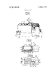
- FIG. 2 is a diagrammatic view in elevation of a chilling tank of the device, being a section along line Il-Il of FIG. 3;
- FIG. 3 is a diagrammatic view in plan of the chilling tank, with a motor hood removed;
- FIG. 4 is an electrical circuit diagram for the chilling tank.
- FIG. 5 is a refrigeration circuit diagram for the tank.
- the assembly which makes possible the application of the cold alcohol method used for the determination of the colloidal stability of beer, comprises a refrigerating or chilling bath 1, in which simple bottles 2 are arranged in order to impart a certain given temperature to the beer contained in the bottles 2, to which an alcohol has been added.
- the amplitude of variation of this temperature must not exceed one tenth of one degree Celsius up or down.
- Observance of this condition is essential for an accurate measurement of turbidity, since the solubility of the turbidity when cold is characterised by the very high thermal gradient of the order of 1.5 units of formazine per degree.
- the bottles 2 are removed individually and are placed in an apparatus 3 enabling the turbidity to be measured; the apparatus 3 in question is of known type and is currently in use.
- the main problem consists of ensuring that all the samples of beer to be tested are at the same predetermined temperature. It is of course necessary for the forming of the turbidity to be fairly sensitive, so that it can be evaluated in a precise manner and, at the same time, the turbidity value must come within the measuring range of the control apparatus 3. In addition, the operating temperature for the test must be sufficiently low to accentuate the formation of turbidity.
- the chilling bath 1 comprises a tank 4 clad in thermal insulating material 5.
- the tank 4 is closed at its upper part 6 by a removable grating 7 having holes 8 of identical diameters.
- the holes 8 are equidistant from one another both along their longitudinal axis and along their transverse axis.
- the bottles 2, containing the beer to be tested, are disposed through the holes 8.
- the plurality of holes 8 enables a number of samples to be tested simultaneously, which is a very great advantage on an industrial scale.
- the bottles 2 occupy a predetermined position and identical circulation passages for the refrigerating liquid result.
- the bottles 2 are thus uniformly chilled. It is important that the level of the chilling liquid shall be at the same height as the level of the volume of liquid to be tested, which is contained in the bottles 2 immersed in said chilling liquid.
- the bottles 2 rest upon a double bottom 9, situated at a certain distance above the bottom 10 of the tank 4.
- an evaporator plate 11 which gives to the chilling liquid contained in the tank 4 the desired temperature.
- a stirrer 12 is immersed vertically in the liquid; the stirrer is driven at its top end by a motor 13.
- the immersed end 14 of the stirrer 12 is provided with a suction and delivery propellor 15.
- the shape, angle and number of the blades 16 are of course predetermined.
- the propellor l5 revolves in a metal duct 17 forming a chimney, the diameter and the height of which have been carefully selected.
- the stirrer 12 operates continuously.
- the chilling liquid is sucked by the propellor l5, ascends in the metal duct 17 and is thrown out at the top into the mass of chilling liquid.
- the metal duct 17 comprises at its top end at least one orifice for the discharge of the liquid sucked by the propellor 15.
- thermometer 18 The temperature of the chilling liquid is controlled by a thermometer 18 with electrical contacts; the thermometer 18 actuates a relay 19 which connects an electrical supply to an electrically operatedvalve 20 mounted in the refrigeration unit.
- FIG. 5 shows the circuit of the refrigeration unit.
- the circuit is divided into a low pressure circuit 21 and a high pressure circuit 22.
- the low pressure circuit 21 comprises all the plant from the needle of a pressure reducing valve 34 to the suction valve of a compressor 26, i.e. duct 35, evaporator plate 11, duct 23, pressure controller 24 and duct 25.
- the high pressure circuit 22 comprises all the plant from the delivery valve of the compressor 26 to the needle of the pressure reducing valve 34, i.e. duct 27, condensor 28, duct 29, storage bottle 30, duct 31, indicator 32, filter 33 and valve 20.
- the assembly comprises of course a cooling fan 36.
- FIG. 4 shows the electrical diagram for controlling the temperature of the chilling bath 1.
- the electrical circuit is supplied from mains 37 by a double interrupter switch 38.
- a visual supply indicator 39 connected across the output terminals of the switch 38, indicates that the supply voltage is available at these terminals; from these terminals there branch in parallel, after the incorporation of a protecting fuse 40, a number of circuits as follows: an electrical circuit 41 for the electric motor of the stirrer 13, followed by an electrical circuit 42 for the electrical motor of the compressor; the pressure controller 24, is mounted in series in the latter circuit.
- Another branch comprises in series a tank level switch 43 and a low level visual indicator 44.
- Another circuit comprises the winding or coil 45 of the relay assembly 19, known by the name of EPSL; the terminals of the relay are shunted by a circuit branch composed of the contacts of the mercury thermometer 18 and of a ballast circuit 46 which is intended, when the shunt circuit is closed, to tap a large proportion of the supply current from the coil 45.
- This coil controls the opening or closing, through the contacts 47, of the relay 19;
- a final branch comprises the supply circuit 48 to the electrically operated valve 20.
- the method of functioning of the chilling bath 1 is as follows: initially, the mercury thermometer 18 operates and itself actuates the relay 19. The relay l9 closes the electrical contact of the electrically operated valve 20 mounted in the high pressure circuit 22 to allow the inflow of refrigerating fluid to the evaporator plate 11. The low pressure increases and the pressure controller 24 switches on the compressor 26. When the desired temperature has been reached, the mercury thermometer 18 cuts the supply to the relay 19 and the electrically operated valve 20 is no longer supplied electrically. There is no further flow of refrigerating fluid. The compressor 26 empties the plate evaporator 1 1, the low pressure falls and the pressure controller 24 cuts the electrical supply to the compressor 26. The method of operation is cyclical.
- a device for determining the colloidal stability of a fermented liquid such as beer comprising a refrigerating bath containing a chilling liquid for imparting a precisely controlled temperature to said fermented liquid and means for measuring the turbidity of the fermented liquid by the cold alcohol method at said controlled temperature, said refrigerating bath comprising a tank clad in thermal insulating material and containing said chilling liquid, a removable grating provided at the upper part of said tank, said grating having holes of identical diameters to receive bottles and arranged at equidistant centres, whereby a plurality of bottles, filled with the liquid to be tested, occupy predetermined positions when placed in the tank according to the arrangement of the holes of the grating, thereby producing identical circulating passages for the chilling liquid between the bottles so as to cool the bottles uniformly, a double bottom disposed at a certain distance from the bottom of the tank, the double bottom serving as a support for the bottles received in said holes in said grating, the position of the double bottom relative
- said stirrer comprises a sucking and delivering propellor provided at the immersed end of a motor driven shaft, and a vertical duct forming a chimney wherein said propellor revolves and having at its upper part at least one orifice for discharging overflow of the chilling liquid drawn up inside the duct by the propellor, whereby a uniform circulation of the chilling liquid is created thus ensuring the homogeneity of the temperature of the liquid in the tank.
- said refrigerating assembly comprises an electrically operated valve connected to said evaporator plate, a relay connected to said valve, a contact thermometer controlling the temperature of the chilling liquid and actuating said relay, and a refrigeration circuit comprising in series said valve and said plate evaporator.
- thermometer is a mercury thermometer with contacts positioned to control the temperature of the chilling liquid to within i0.lC of a predetermined temperature.
- a device for determining the colloidal stability of a fermented liquid such as beer comprising a refrigerating bath containing a chilling liquid for imparting a precisely controlled temperature to said fermented liquid and means for measuring the turbidity of the fermented liquid by the cold alcohol method at said controlled temperature, said refrigerating bath comprising a tank clad in thermal insulating material and containing said chilling liquid, a removable grating provided at the upper part of said tank, said grating having holes of identical diameters to receive bottles and arranged at equidistant centres, whereby a plurality of bottles, filled with the liquid to be tested, occupy predetermined positions when placed in the tank according to the arrangement of the holes of the grating,
Landscapes
- Engineering & Computer Science (AREA)
- Food Science & Technology (AREA)
- Health & Medical Sciences (AREA)
- Life Sciences & Earth Sciences (AREA)
- Chemical & Material Sciences (AREA)
- Medicinal Chemistry (AREA)
- Physics & Mathematics (AREA)
- Analytical Chemistry (AREA)
- Biochemistry (AREA)
- General Health & Medical Sciences (AREA)
- General Physics & Mathematics (AREA)
- Immunology (AREA)
- Pathology (AREA)
- Investigating Or Analyzing Materials Using Thermal Means (AREA)
- Distillation Of Fermentation Liquor, Processing Of Alcohols, Vinegar And Beer (AREA)
Applications Claiming Priority (1)
| Application Number | Priority Date | Filing Date | Title |
|---|---|---|---|
| FR7309798A FR2221996A5 (enExample) | 1973-03-12 | 1973-03-12 |
Publications (1)
| Publication Number | Publication Date |
|---|---|
| US3901068A true US3901068A (en) | 1975-08-26 |
Family
ID=9116520
Family Applications (1)
| Application Number | Title | Priority Date | Filing Date |
|---|---|---|---|
| US385242A Expired - Lifetime US3901068A (en) | 1973-03-12 | 1973-08-03 | Device for determining the colloidal stability of a liquid |
Country Status (5)
| Country | Link |
|---|---|
| US (1) | US3901068A (enExample) |
| DE (1) | DE2331231A1 (enExample) |
| FR (1) | FR2221996A5 (enExample) |
| GB (1) | GB1403848A (enExample) |
| NL (1) | NL7403342A (enExample) |
Cited By (1)
| Publication number | Priority date | Publication date | Assignee | Title |
|---|---|---|---|---|
| CN105954312A (zh) * | 2016-07-13 | 2016-09-21 | 广东工业大学 | 一种固液相变材料的热稳定性测试系统 |
Families Citing this family (2)
| Publication number | Priority date | Publication date | Assignee | Title |
|---|---|---|---|---|
| FR2478818A1 (fr) * | 1980-03-24 | 1981-09-25 | Tepral Ctre Rech Dev | Appareil et procede de mesure de la stabilite colloidale de liquides |
| FR3070763B1 (fr) * | 2017-09-06 | 2021-01-22 | Systel Electronique | Appareil et procede de suivi de la vinification |
Citations (3)
| Publication number | Priority date | Publication date | Assignee | Title |
|---|---|---|---|---|
| US2546417A (en) * | 1948-05-14 | 1951-03-27 | William E Anglin | Refrigerating apparatus for beverage coolers |
| US2575796A (en) * | 1948-08-20 | 1951-11-20 | Conklin Stanley | Refrigerating cabinet for milk samples |
| US3188857A (en) * | 1962-08-27 | 1965-06-15 | Phillips Petroleum Co | Method and apparatus for concentration measurement and control |
-
1973
- 1973-03-12 FR FR7309798A patent/FR2221996A5/fr not_active Expired
- 1973-06-11 GB GB2760073A patent/GB1403848A/en not_active Expired
- 1973-06-19 DE DE2331231A patent/DE2331231A1/de active Pending
- 1973-08-03 US US385242A patent/US3901068A/en not_active Expired - Lifetime
-
1974
- 1974-03-12 NL NL7403342A patent/NL7403342A/xx not_active Application Discontinuation
Patent Citations (3)
| Publication number | Priority date | Publication date | Assignee | Title |
|---|---|---|---|---|
| US2546417A (en) * | 1948-05-14 | 1951-03-27 | William E Anglin | Refrigerating apparatus for beverage coolers |
| US2575796A (en) * | 1948-08-20 | 1951-11-20 | Conklin Stanley | Refrigerating cabinet for milk samples |
| US3188857A (en) * | 1962-08-27 | 1965-06-15 | Phillips Petroleum Co | Method and apparatus for concentration measurement and control |
Cited By (2)
| Publication number | Priority date | Publication date | Assignee | Title |
|---|---|---|---|---|
| CN105954312A (zh) * | 2016-07-13 | 2016-09-21 | 广东工业大学 | 一种固液相变材料的热稳定性测试系统 |
| CN105954312B (zh) * | 2016-07-13 | 2018-12-18 | 广东工业大学 | 一种固液相变材料的热稳定性测试系统 |
Also Published As
| Publication number | Publication date |
|---|---|
| FR2221996A5 (enExample) | 1974-10-11 |
| GB1403848A (en) | 1975-08-28 |
| NL7403342A (enExample) | 1974-09-16 |
| DE2331231A1 (de) | 1974-10-03 |
Similar Documents
| Publication | Publication Date | Title |
|---|---|---|
| US3327535A (en) | Multiple pipetting apparatus | |
| US3677064A (en) | Apparatus for automatic crystal point detection | |
| US3901068A (en) | Device for determining the colloidal stability of a liquid | |
| US4282745A (en) | Particle size determination | |
| US2348806A (en) | Sewage sampler | |
| US2711750A (en) | Apparatus for controlling the viscosity of a processing liquid | |
| US2167185A (en) | Bottle testing apparatus | |
| DE3928130A1 (de) | Verfahren zur pruefung des widerstands von werkstoffen oder bauteilen gegen den kombinierten angriff von frost-tau-wechsel und waessriger loesung | |
| US4106331A (en) | Method and apparatus for detecting contamination of liquids | |
| DE4036344C2 (de) | Meßverfahren und Meßinstrument zur Bestimmung des Schaumbildungs- und -zerfallverhaltens von Flüssigkeiten | |
| US3540264A (en) | Automatic viscometer | |
| GB1511737A (en) | Apparatus for use in investigating specimens | |
| US3161039A (en) | Apparatus for determining pour point | |
| JPS60263836A (ja) | 液槽式熱衝撃試験装置 | |
| US3294101A (en) | Immersion treatment apparatus | |
| US2134787A (en) | Method of and apparatus for preparing beverages | |
| US4061016A (en) | Method and apparatus for measuring the foam life on an effervescent beverage | |
| US3428487A (en) | Apparatus and method for producing sugar solutions | |
| US3092882A (en) | Apparatus for measuring and controlling moisture content of materials | |
| US2962360A (en) | Automatic carbon determinator | |
| US3815424A (en) | Apparatus for filtering and density determination of a liquid | |
| US3284164A (en) | Apparatus for automatic analyzing | |
| US3014804A (en) | Method for producing acetic acid from alcohol containing fermentation medium | |
| US1945822A (en) | Method and apparatus for measuring viscosity | |
| US2875590A (en) | Equipment and process for attempering, storing, and weighing |