US3872679A - Apparatus and method for reducing the forces on extendible legs of a floating vessel - Google Patents
Apparatus and method for reducing the forces on extendible legs of a floating vessel Download PDFInfo
- Publication number
- US3872679A US3872679A US427175A US42717573A US3872679A US 3872679 A US3872679 A US 3872679A US 427175 A US427175 A US 427175A US 42717573 A US42717573 A US 42717573A US 3872679 A US3872679 A US 3872679A
- Authority
- US
- United States
- Prior art keywords
- legs
- vessel
- submersible
- semi
- water
- Prior art date
- Legal status (The legal status is an assumption and is not a legal conclusion. Google has not performed a legal analysis and makes no representation as to the accuracy of the status listed.)
- Expired - Lifetime
Links
Images


Classifications
-
- E—FIXED CONSTRUCTIONS
- E02—HYDRAULIC ENGINEERING; FOUNDATIONS; SOIL SHIFTING
- E02B—HYDRAULIC ENGINEERING
- E02B17/00—Artificial islands mounted on piles or like supports, e.g. platforms on raisable legs or offshore constructions; Construction methods therefor
- E02B17/02—Artificial islands mounted on piles or like supports, e.g. platforms on raisable legs or offshore constructions; Construction methods therefor placed by lowering the supporting construction to the bottom, e.g. with subsequent fixing thereto
- E02B17/021—Artificial islands mounted on piles or like supports, e.g. platforms on raisable legs or offshore constructions; Construction methods therefor placed by lowering the supporting construction to the bottom, e.g. with subsequent fixing thereto with relative movement between supporting construction and platform
-
- E—FIXED CONSTRUCTIONS
- E02—HYDRAULIC ENGINEERING; FOUNDATIONS; SOIL SHIFTING
- E02B—HYDRAULIC ENGINEERING
- E02B17/00—Artificial islands mounted on piles or like supports, e.g. platforms on raisable legs or offshore constructions; Construction methods therefor
- E02B2017/0056—Platforms with supporting legs
Definitions
- the method of their use requires lowering the extendible main supporting legs of a jack-up drilling vessel above the ocean floor, lowering the semisubmersible legs into the water, making them buoyant so as to cause the vessel to raise out of the water to a distance above probable wave action at which time the extendible main support legs are lowered to a supporting position onto or into the ocean floor.
- the semi-submersible legs With the extendible supporting legs in a supporting position, the semi-submersible legs are retracted; if the extendible legs penetrate a soft bottom, the semi-submersible legs are first ballasted to serve as an additional jacking down source for the supporting legs and then retracted and deballasted,
- the foregoing steps are reversed when the drilling vessel is to be relocated with or without the supplemental steps of making the semisubmersible legs additionally buoyant and or lowering the vessel bull to the water surface thus providing an extra lift force on the support legs.
- the vessel hull is jacked up on the buoyant support of the semisubmersible legs prior to completely removing the extendible main legs from the ocean floor penetration or surace contact.
- HARE 51975 sums or 5 APPARATUS AND METHOD FOR REDUCING THE FORCES ON EXTENDIBLE LEGS OF A FLOATING VESSEL BACKGROUND OF THE INVENTION 1.
- This invention relates to marine structures. Specifically, this invention is related to a new component of a mobile drilling vessel which reduces the destructive forces on extendible support legs during the following intervals: when legs are moved from a stowed position on the drilling vessel into a load supporting position into or on the ocean floor and especially during the interval when the support legs are near the ocean floor while the vessel is subject to rough water conditions. The invention is also used when the supporting legs are removed from the bottom and put into a stowed position.
- the ramming and ripping forces mentioned above occur during the interval when the legs are being located on or into the bottom or when the supporting columns are moved off and away from the bottom in preparation for moving the barge to another site; or more precisely, during the interval when the total weight of the vessel transfers from the buoyant support of the water to a fixed support on the water or ocean floor and vice versa.
- the vessel is subjected to roll, pitch and heave and combinations thereof which result in accentuating vertical, lateral, and the combination of these motions at the bottom of the legs relative to the ocean floor. lfthe critical weight shift from buoyant to on-bottom support or the reverse is undertaken when wave heights exceed 3 to 5 feet, violent and sometimes destructive forces are developed from the main legs vertically impacting and ripping through the ocean floor, at times resulting in severe leg damage.
- This invention is a novel way to reduce destructive forces on extendible main supporting legs of movable offshore platforms while they are moved into or removed from a load transferring position; in other words, a way to permit soft touch landings and departures of the main support legs from the ocean floor.
- the improvement involves the lowering of adjustably buoyant semi-submersible legs which lift the floating platform out of the water after the main supporting legs are lowered and locked at a water depth precluding any possibility of bottom contact. This sequence establishes optimum vessel stability while the semisubmersible legs lift and/or support the vessel out of the water clear of probable wave action.
- the buoyant semi-submersible legs provide a minimum motion flotation to the jack-up drilling vessel and its extended main legs, particularly during the critical interval when the vessel weight shifts from the buoyant support of the vessel to the bottom engaging main legs.
- the primary reason vessel and related main leg motion are reduced is that wave-induced fluctuations of the water surface at the drilling site run up and down a relatively minimal water displacing volume on the semisubmersible buoyant support system, thus contributing small buoyant force changes and, therefore, small vessel and main leg movements.
- this same wave action produces large buoyancy changes and therefore, large vessel and main leg movement.
- the semi-submersible legs With the main legs in a load carrying position on the ocean floor, the semi-submersible legs are retracted. If, however, the main support legs require further penetration into the ocean floor to support future maximum drilling hook or other loads, a convenient loading means for seating the legs in a final supporting position is available by retracting the semisubmersible legs and ballasting them. In this way, for example, twice the total weight of the rig can be exerted as a downward force on the support legs.
- the semi-submersible legs When moving from a completed drilling operation, the semi-submersible legs are lowered a safe distance above the ocean floor, locked, and then deballasted as required to lift the vessel hull and the main supporting legs. If the main legs transfer their load to a hard bot-' tom, raising these legs presents no problem or at most requires a conventional water pressure vacuum breaker assist below the main legs. If the legs required deep penetration at installation and/or the soil resistance to removal requires more upward force to overcome than that developed by the maximum lift supplied by the semi-submersible legs and water vacuum breaking pressure, it may become necessary to lower the vessel hull onto the water surface for its potentially greater uplift capability. The vessel's buoyancy is used to break free the main legs without removing them completely from their holes. The hull is then jacked up out of the water for safe removal of the main legs from the holes while being supported on its semi-submersible legs. As
- the hull is again floated.
- the semi-submersible legs are fully retracted and locked after which the main legs are also fully retracted and locked.
- the rig is now ready to move to the next location.
- a few other examples of difficulties which this invention can alleviate is unequal platform jacking caused by jack binding, uneven water bottoms, and driving a supporting column into a weaker soil strata than the other main supporting legs.
- the invention also makes possible a damage control method.
- a damage control method For example, when ajack-up platform, though safely positioned with extendible legs on the ocean floor is struck by catastrophe, this invention can serve as an additional safety factor which might be moved into operation, such a catastrophe is exemplified by an accidental ramming as by a large supply vessel with sufficient force to cause damage which may lead to ultimate destruction of one or more main legs.
- the remaining main legs must support not only the original load, but also each main leg must resist ad ditional moment induced by any deformation in it. Total collapse of this platform and loss of human life could occur.
- the semisubmersible legs of this invention offer some opportunity of supplementary or standby support which could mean the difference between saving the rig and a total loss of it.
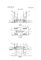
- FIG. 1 is a schematic showing an elevation of a jackup barge embodying the invention with the elements in position for towing the jack-up barge from one location to another;
- FIG. 2 is a schematic plan view of FIG. 1;
- FIG. 3 is a schematic elevation view showing the main supporting legs and semi-submersible legs partially lowered and locked in position.
- FIG. 4 is a schematic elevation view showing the buoyant semi-submersible legs lifting the working platform of the drilling vessel clear of the water and probable wave action into a motion dampening position.
- FIG. 5 is a schematic elevation view showing the sup porting main legs lowered in a platform supporting position before the semi-submersible legs are retracted.
- FIG. 6 is a schematic elevation view showing the supporting columns in a platform supporting position and the semi-submersible legs fully retracted.
- FIG. 7 is a schematic elevation showing the vessel positioned as a drilling platform with the drilling mast in an operating position.
- FIG. 8 is a three dimensional view illustrating in more detail the vessel including the energy lines for jacking and locking the legs in position.
- the mobile jack-up drilling vessel is designated 50.
- the equipment used in offshore operations is mounted on the vessel deck 51 which forms the platform 59, FIG. 4; however, only the drilling mast 52 in a stowed position is shown.
- the combined weight of the vessel 50 includes the weight of the platform 59, the extendible main supporting legs 56, the semisubmersible legs 57, and anything else on or in the vessel for whatever reason.
- passages which in the preferred embodiment are vertically oriented sleeves 55.
- a first set of the sleeves 55 serve as vertical guides for raising or lowering of the main support legs 56 and a second set is provided for the special semisubmersible legs 57 to serve a like function.
- the sleeves 55 are hollow tubular shaped components made from steel or other materials and are welded or otherwise fastened to the vessel hull 53.
- the semi-submersible ad justably buoyant legs 57 are hollow controllably buoyant water-tight components which can become sufficiently buoyant to raise the vessel 50 out of the water; or alternatively ballasted so as to sink in the water.
- the semi-submersible legs 57 are made of steel or similar materials and can take the shape of a closed ended cylinder with the end 66 which first enters the water expanded in the shape of a large cylinder 67 concentric with and permanently fastened to a smaller upper cylinder 68 as shown in FIG. 3.
- the foregoing describes an embodiment of the semi-submersible adjustably buoyant leg means.
- the mobile jack-up drilling vessel 50 may be surface towed or self-propelled from one location to another.
- the main extendible supporting legs 56 after ballasting if required, are lowered as far down as possible without danger of bottom contact due to hull motion as shown in FIG. 3, and locked in this position to provide optimum vessel hull stability while being lifted and supported above the water surface by the semisubmersible legs 57.
- the semi-submersible legs 57 are controllably lowered by ballasting or jacking or a combination of the two methods and then locked in position as shown in FIG. 3.
- the jacking and locking mechanism 58 which provides controlled movement through a second set of the sleeves 55 is of conventional design being either mechanical, hydraulic or pneumatic or a combination of these.
- a schematic arrangement of the control console 60, energy source 64 and lines 61 is shown in FIG. 8. In this lowered position, shown in FIG. 4, the semisubmersible legs 57 are made buoyant through a blowing out process or other equivalent way. The buoyancy causes the vessel hull 53 to raise out of the water as shown in FIG. 4.
- the vessel hull 53 becomes a platform 59 with the semi-submersible legs 57 as the sole support unless the partially lowered main legs 56 are made buoyant to assist.
- This new position results in less heave, roll and pitch to the platform 59 than if it were floating on the water. Consequently. the shift from the buoyant support of the semi-submersible legs 57 to the main supporting legs 56 fixed on the bottom or a shift from the main leg support 56 to a buoyant support is accomplished safely and without main leg 56 damage or failure in rougher waters than was possible without the semi-submersible legs 57.
- the distance the vessel hull 53 is raised above the water surface is governed by the possible wave heights that are forecasted for the estimated duration of operations at the drilling location since wave impact on the vessel hull 53 could cause major damage. In calm waters this distance may be only feet or less. In rougher seas, such as the North Sea, it may be 30 feet or more above the water surface. In any case, the prudent oper ator will elevate the vessel hull 53 safely above the highest waves expected on the drilling location over the estimated period of drilling operations.
- the main supporting legs 56 are unlocked from their partially lowered position, lowered or jacked down into an on-bottom position, as shown in FIG. 5, and locked. Subsequently, there is a trial deballasting of the semi-submersible legs 57 to determine whether or not any of the main legs 56 are on weak or easily compressible soil requiring further lowering those particular legs; otherwise, the semi-submersible legs 57 are fully retracted, locked, and ballasted as required to drive and/or load test the main legs 56.
- the jacking and locking mechanism 54 which provides the controlled movement for the main support legs 56 through a first set of sleeves 55 is shown in FIG. 8 where the control console 63, energy source 64 and lines 65 are illustrated.
- the vessel 50 With the supporting legs 56 in a platform supporting position, the vessel 50 is jacked up on the main supporting legs 56 to a safe height above the maximum expected wave crests; after support leg loadings are equalized they are locked into position by conventional mechanically, hydraulically or pneumatically actuated means 54 schematically shown in FIG. 8 where the control console 63, energy source 64 and lines 65 are shown.
- This jacking procedure not only guarantees that the deck 51 is located at the desired elevation but also serves as a test to guarantee that the main support legs 56 are able to support the maximum load incurred in the drilling operations.
- the retracted semi-submersible legs 57 are then deballasted. With the semi-submersible legs 57 retracted, FIG. 6, they do not transmit lateral loads to the main supporting legs 56 from possible impact by waves lower than the maximum height expected.
- the drilling mast 52 is then moved in a working position as shown in FIG. 7.
- the vessel hull 53 through properly coordinated manipulation'of the jacks and the locking gear 58 and the semi-submersible legs 57, is movable up or down on the main supporting legs 56.
- the semisubmersible legs 57 are lowered a safe distance above the water bottom, locked, and then deballasted as required to lift the vessel hull 53 and the main supporting legs 56 similar to FIG. 5. If the main legs 56 transfer their load to a hard bottom, raising these legs 56 presents little difficulty. In the case, however, where the legs 56 required deep penetration at installation and/or the soil comprising the underwater bottom offers more resistance to removal than the uplift supplied by the semi-submersible legs 57 and conventional methods of removal like water vacuum breaking pressure (not illustrated), the vessel hull 53 is lowered onto the water surface to provide greater uplift capability. The foregoing steps are used to provide just that amount of uplift force necessary to break free the main legs 56 without removing them from their holes 69.
- the vessel hull 53 is then jacked up out of the water for removal of the main legs 56 from the holes 69 while being supported on its semi-submersible legs 57. As soon as the legs 56 are high enough above the water bottom to avoid contact with it, the legs 56 are locked, FIG. 4, and the vessel hull 53 is again floated, FIG. 3. The semisubmersible legs 57 are fully retracted and locked after which the main legs 56 are also fully retracted and locked, FIG. I. The vessel 50 is now ready to be relocated.
- a vessel adapted to float on a body of water comprising: a platform; a plurality of passages through said platform; a plurality of main supporting legs operatively and adjustably connected to said platform; means permitting said main legs to have controlled movement through a first set of said passages; semi-submersible leg means operatively and adjustably connected to said platform for providing sufficient buoyancy to raise and support the combined weight of said vessel above the surface of said water while said main legs are moved into a supporting position in contact with the underwater bottom for said platform.
- the vessel of claim 1 including a jacking means for raising and lowering said platform on said supporting main legs in conjunction with the buoyant force of said semi-submersible legs when said main legs are in a platform supporting position.
- said semisubmersible leg means consists of four semisubmersible legs operatively and adjustably connected to said platform; a means permitting said semisubmersible legs to have controlled movement through a second set of said passages; said semi-submersible legs providing sufficient buoyancy to raise and support the combined weight of said vessel above the surface of said water while said main legs are moved into a supporting position.
- a method of reducing destructive forces on a set of supporting main legs of a vessel floating on a body of water while said main legs are lowered into a position in contact with the underwater bottom comprising the steps of: lowering into said water a set of supporting main legs to a position above said underwater bottom so as to avoid contact with said underwater bottom; extending a semi-submersible controllably buoyant means operatively and adjustably connected to said vessel into said body of water; increasing the buoyancy of said means to raise said vessel to a predetermined height; positioning said main legs into a platform supporting position in contact with said underwater bottom; and retracting said semi-submersible controllably buoyant means to said vessel.
- a method of reducing destructive forces on a set of main supporting legs of a vessel floating on a body of water while said main legs are lowered into a position in contact with the underwater bottom comprising the steps of: lowering into said water a set of supporting main legs to a position above said underwater bottom; extending a semi-submersible controllably buoyant means operatively and adjustably connected to said vessel into said body of water; increasing the buoyancy of said means to raise said vessel to a predetermined height; positioning said main legs into a platform supporting position in contact with said underwater bottom; ballasting said semi-submersible means so as to add additional jacking force to said main legs and serve as a load test on said main legs; retracting said semisubmersible means; and deballasting said semisubmersible means.
- a method of reducing destructive forces on a set of supporting main legs of a jacked up vessel located over a body of water while said main legs are raised into a stowed position comprising the steps of: extending a semi-submersible controllably buoyant means operatively and adjustably connected to said vessel into an underlying body of water; increasing the buoyancy of said means to support said vessel at a predetermined height; raising from said water bottom a set of supporting main legs to a predetermined height above said bottom; lowering said vessel to said water surface; retracting said semi-submersible means to said vessel; and retracting said main legs into a stowed position on said vessel.
- the method of claim 9 including the additional step of further increasing the buoyancy of said semisubmersible controllably buoyant means to provide a lifting force on said main legs.
- a method of reducing destructive forces on a set of supporting main legs of a jacked up vessel located over a body of water, wherein said main legs are embedded in the underwater bottom, while said main legs are raised into a stowed position from said underwater bottom comprising the steps of: extending a semisubmersible controllably buoyant means operatively and adjustably connected to said vessel into an underlying body of water; lowering said vessel to said water surface to provide a buoyant force; increasing the buoyancy of said means to aid in loosening said main legs; loosening said main legs; raising said vessel to a predetermined height above said water surface on said means; raising said main legs to a predetermined height above said underwater bottom; lowering said vessel to the water surface; retracting said semi-submersible means to said vessel; and retracting said main legs into a stowed position on said vessel.
Landscapes
- Engineering & Computer Science (AREA)
- General Engineering & Computer Science (AREA)
- Mechanical Engineering (AREA)
- Civil Engineering (AREA)
- Structural Engineering (AREA)
- Earth Drilling (AREA)
- Prostheses (AREA)
- Rigid Containers With Two Or More Constituent Elements (AREA)
- Electrophotography Configuration And Component (AREA)
- Load-Engaging Elements For Cranes (AREA)
Abstract
Semi-submersible legs are embodied as close-ended cylinders or other similar shapes or combination of shapes having the capability to be ballasted or made buoyant. The semi-submersible legs are connected to a jack-up drilling vessel so that they slide vertically through the vessel deck into the underlying body of water and are lockable at any position along their vertical path. The method of their use requires lowering the extendible main supporting legs of a jack-up drilling vessel above the ocean floor, lowering the semi-submersible legs into the water, making them buoyant so as to cause the vessel to raise out of the water to a distance above probable wave action at which time the extendible main support legs are lowered to a supporting position onto or into the ocean floor. With the extendible supporting legs in a supporting position, the semi-submersible legs are retracted; if the extendible legs penetrate a soft bottom, the semi-submersible legs are first ballasted to serve as an additional jacking down source for the supporting legs and then retracted and deballasted. The foregoing steps are reversed when the drilling vessel is to be relocated with or without the supplemental steps of making the semi-submersible legs additionally buoyant and or lowering the vessel hull to the water surface thus providing an extra lift force on the support legs. The vessel hull is jacked up on the buoyant support of the semisubmersible legs prior to completely removing the extendible main legs from the ocean floor penetration or surace contact.
Description
United States Patent [19] Fischer 1 Mar. 25, 1975 [54] APPARATUS AND METHOD FOR REDUCING THE FORCES ON EXTENDIBLE LEGS OF A FLOATING VESSEL [75] Inventor: William Fischer, Fullerton, Calif.
[73] Assignee: Chevron Research Company, San
Francisco, Calif.
[22] Filed: Dec. 21, 1973 [21] Appl. N0.: 427,175
[52] US. Cl. 61/465, 114/.5 D
[51] Int. Cl. E02b 17/00, B63b 35/00 [58] Field of Search 61/465, 65; 114/.5 D; 175/7, 8, 9
[56] References Cited UNlTED STATES PATENTS 2,771,747 11/1956 Rechtin 61/465 2841961 7/1958 Lucas 61/465 3.605669 9/1971 Yu 61/465 X Primary Examiner-Jacob Shapiro Attorney, Agent, or FirmRalph L. Freeland, .lr.; Robert T. Kloeppel [57] ABSTRACT Semi-sumbersible legs are embodied as close-ended cylinders or other similar shapes or combination of shapes having the capability to be ballasted or made buoyant. The semi-submersible legs are connected to a jack-up drilling vessel so that they slide vertically through the vessel deck into the underlying body of water and are lockable at any position along their vertical path. The method of their use requires lowering the extendible main supporting legs of a jack-up drilling vessel above the ocean floor, lowering the semisubmersible legs into the water, making them buoyant so as to cause the vessel to raise out of the water to a distance above probable wave action at which time the extendible main support legs are lowered to a supporting position onto or into the ocean floor. With the extendible supporting legs in a supporting position, the semi-submersible legs are retracted; if the extendible legs penetrate a soft bottom, the semi-submersible legs are first ballasted to serve as an additional jacking down source for the supporting legs and then retracted and deballasted, The foregoing steps are reversed when the drilling vessel is to be relocated with or without the supplemental steps of making the semisubmersible legs additionally buoyant and or lowering the vessel bull to the water surface thus providing an extra lift force on the support legs. The vessel hull is jacked up on the buoyant support of the semisubmersible legs prior to completely removing the extendible main legs from the ocean floor penetration or surace contact.
12 Claims, 8 Drawing Figures :::::gi l
PATENTEI] HARE 51975 sums or 5 APPARATUS AND METHOD FOR REDUCING THE FORCES ON EXTENDIBLE LEGS OF A FLOATING VESSEL BACKGROUND OF THE INVENTION 1. Field of the Invention This invention relates to marine structures. Specifically, this invention is related to a new component of a mobile drilling vessel which reduces the destructive forces on extendible support legs during the following intervals: when legs are moved from a stowed position on the drilling vessel into a load supporting position into or on the ocean floor and especially during the interval when the support legs are near the ocean floor while the vessel is subject to rough water conditions. The invention is also used when the supporting legs are removed from the bottom and put into a stowed position.
2. Description of Prior Art Offshore drilling vessels which are self-propelled or towed on the water surface from one location to another have been used in the past. One type of such vessel is supported and jacked clear of the water surface on extendible legs that are lowered to the water bottom when a site is reached. In this jacked up position the vessel becomes a stable drilling platform. However, the extendible legs have experienced much damage, including ultimate failure in some instances, due to the legs ramming against and/or ripping through the under water bottom in even relatively calm water; that is, waves between 3 to 5 feet. In some offshore areas like the Gulf of Alaska or the North Sea, the wave heights are rarely below the safe limit for the transfer of drilling vessel weight from the vessels buoyant support to the extendible leg support when moving into a location, and the transfer from the extendible legs to the buoyant support of the vessel when relocating. The only alternative to gambling on damage to the extendible legs is the common and costly practice of awaiting calm seas. Despite this basic vulnerability in a mobile jack-up drilling vessel, many drilling companies and oil operating companies favor their use over other types of drilling vessels because they offer virtually the same stable support features as a permanently fixed platform, yet being capable of relocation on short notice without the commitment of a major capital expenditure before the extent of petroleum deposits are ascertained.
The ramming and ripping forces mentioned above occur during the interval when the legs are being located on or into the bottom or when the supporting columns are moved off and away from the bottom in preparation for moving the barge to another site; or more precisely, during the interval when the total weight of the vessel transfers from the buoyant support of the water to a fixed support on the water or ocean floor and vice versa. During any of the foregoing times the vessel is subjected to roll, pitch and heave and combinations thereof which result in accentuating vertical, lateral, and the combination of these motions at the bottom of the legs relative to the ocean floor. lfthe critical weight shift from buoyant to on-bottom support or the reverse is undertaken when wave heights exceed 3 to 5 feet, violent and sometimes destructive forces are developed from the main legs vertically impacting and ripping through the ocean floor, at times resulting in severe leg damage.
SUMMARY OF THE INVENTION This invention is a novel way to reduce destructive forces on extendible main supporting legs of movable offshore platforms while they are moved into or removed from a load transferring position; in other words, a way to permit soft touch landings and departures of the main support legs from the ocean floor. The improvement involves the lowering of adjustably buoyant semi-submersible legs which lift the floating platform out of the water after the main supporting legs are lowered and locked at a water depth precluding any possibility of bottom contact. This sequence establishes optimum vessel stability while the semisubmersible legs lift and/or support the vessel out of the water clear of probable wave action. Further, in this position, the buoyant semi-submersible legs provide a minimum motion flotation to the jack-up drilling vessel and its extended main legs, particularly during the critical interval when the vessel weight shifts from the buoyant support of the vessel to the bottom engaging main legs. The primary reason vessel and related main leg motion are reduced is that wave-induced fluctuations of the water surface at the drilling site run up and down a relatively minimal water displacing volume on the semisubmersible buoyant support system, thus contributing small buoyant force changes and, therefore, small vessel and main leg movements. Whereas, when running up and down on a massive conventional vessel hull floating on the surface of the water, this same wave action produces large buoyancy changes and therefore, large vessel and main leg movement.
With the main legs in a load carrying position on the ocean floor, the semi-submersible legs are retracted. If, however, the main support legs require further penetration into the ocean floor to support future maximum drilling hook or other loads, a convenient loading means for seating the legs in a final supporting position is available by retracting the semisubmersible legs and ballasting them. In this way, for example, twice the total weight of the rig can be exerted as a downward force on the support legs.
When moving from a completed drilling operation, the semi-submersible legs are lowered a safe distance above the ocean floor, locked, and then deballasted as required to lift the vessel hull and the main supporting legs. If the main legs transfer their load to a hard bot-' tom, raising these legs presents no problem or at most requires a conventional water pressure vacuum breaker assist below the main legs. If the legs required deep penetration at installation and/or the soil resistance to removal requires more upward force to overcome than that developed by the maximum lift supplied by the semi-submersible legs and water vacuum breaking pressure, it may become necessary to lower the vessel hull onto the water surface for its potentially greater uplift capability. The vessel's buoyancy is used to break free the main legs without removing them completely from their holes. The hull is then jacked up out of the water for safe removal of the main legs from the holes while being supported on its semi-submersible legs. As
soon as the legs are high enough above the water bottom to preclude contact with it, the hull is again floated. The semi-submersible legs are fully retracted and locked after which the main legs are also fully retracted and locked. The rig is now ready to move to the next location.
The proper use of this invention will significantly reduce costly weather downtime and costly repair operations resulting from unsuccessful attempts to move in or move out of location in wave conditions exceeding allowable limits.
A few other examples of difficulties which this invention can alleviate is unequal platform jacking caused by jack binding, uneven water bottoms, and driving a supporting column into a weaker soil strata than the other main supporting legs.
The invention also makes possible a damage control method. For example, when ajack-up platform, though safely positioned with extendible legs on the ocean floor is struck by catastrophe, this invention can serve as an additional safety factor which might be moved into operation, such a catastrophe is exemplified by an accidental ramming as by a large supply vessel with sufficient force to cause damage which may lead to ultimate destruction of one or more main legs. When this occurs, the remaining main legs must support not only the original load, but also each main leg must resist ad ditional moment induced by any deformation in it. Total collapse of this platform and loss of human life could occur. In such cases the semisubmersible legs of this invention offer some opportunity of supplementary or standby support which could mean the difference between saving the rig and a total loss of it.
BRIEF DESCRIPTION OF DRAWINGS FIG. 1 is a schematic showing an elevation of a jackup barge embodying the invention with the elements in position for towing the jack-up barge from one location to another;
FIG. 2 is a schematic plan view of FIG. 1;
FIG. 3 is a schematic elevation view showing the main supporting legs and semi-submersible legs partially lowered and locked in position.
FIG. 4 is a schematic elevation view showing the buoyant semi-submersible legs lifting the working platform of the drilling vessel clear of the water and probable wave action into a motion dampening position.
FIG. 5 is a schematic elevation view showing the sup porting main legs lowered in a platform supporting position before the semi-submersible legs are retracted.
FIG. 6 is a schematic elevation view showing the supporting columns in a platform supporting position and the semi-submersible legs fully retracted.
FIG. 7 is a schematic elevation showing the vessel positioned as a drilling platform with the drilling mast in an operating position.
FIG. 8 is a three dimensional view illustrating in more detail the vessel including the energy lines for jacking and locking the legs in position.
DESCRIPTION OF THE PREFERRED EMBODIMENT EMBODIMENT Referring to FIG. 1, the mobile jack-up drilling vessel is designated 50. The equipment used in offshore operations is mounted on the vessel deck 51 which forms the platform 59, FIG. 4; however, only the drilling mast 52 in a stowed position is shown. The combined weight of the vessel 50 includes the weight of the platform 59, the extendible main supporting legs 56, the semisubmersible legs 57, and anything else on or in the vessel for whatever reason.
Passing through the vessel hull 53 and vessel deck 51, as shown in FIGS. 1 and 2, are passages which in the preferred embodiment are vertically oriented sleeves 55. A first set of the sleeves 55 serve as vertical guides for raising or lowering of the main support legs 56 and a second set is provided for the special semisubmersible legs 57 to serve a like function. The sleeves 55 are hollow tubular shaped components made from steel or other materials and are welded or otherwise fastened to the vessel hull 53. The semi-submersible ad justably buoyant legs 57 are hollow controllably buoyant water-tight components which can become sufficiently buoyant to raise the vessel 50 out of the water; or alternatively ballasted so as to sink in the water. The semi-submersible legs 57 are made of steel or similar materials and can take the shape of a closed ended cylinder with the end 66 which first enters the water expanded in the shape of a large cylinder 67 concentric with and permanently fastened to a smaller upper cylinder 68 as shown in FIG. 3. The foregoing describes an embodiment of the semi-submersible adjustably buoyant leg means.
When the semi-submersible legs 57 and the main supporting legs 56 are in an upright position as shown in FIG. 1, the mobile jack-up drilling vessel 50 may be surface towed or self-propelled from one location to another. When a drilling location is reached, the main extendible supporting legs 56, after ballasting if required, are lowered as far down as possible without danger of bottom contact due to hull motion as shown in FIG. 3, and locked in this position to provide optimum vessel hull stability while being lifted and supported above the water surface by the semisubmersible legs 57.
The semi-submersible legs 57 are controllably lowered by ballasting or jacking or a combination of the two methods and then locked in position as shown in FIG. 3. The jacking and locking mechanism 58 which provides controlled movement through a second set of the sleeves 55 is of conventional design being either mechanical, hydraulic or pneumatic or a combination of these. A schematic arrangement of the control console 60, energy source 64 and lines 61 is shown in FIG. 8. In this lowered position, shown in FIG. 4, the semisubmersible legs 57 are made buoyant through a blowing out process or other equivalent way. The buoyancy causes the vessel hull 53 to raise out of the water as shown in FIG. 4. In the new position, the vessel hull 53 becomes a platform 59 with the semi-submersible legs 57 as the sole support unless the partially lowered main legs 56 are made buoyant to assist. This new position results in less heave, roll and pitch to the platform 59 than if it were floating on the water. Consequently. the shift from the buoyant support of the semi-submersible legs 57 to the main supporting legs 56 fixed on the bottom or a shift from the main leg support 56 to a buoyant support is accomplished safely and without main leg 56 damage or failure in rougher waters than was possible without the semi-submersible legs 57.
The distance the vessel hull 53 is raised above the water surface is governed by the possible wave heights that are forecasted for the estimated duration of operations at the drilling location since wave impact on the vessel hull 53 could cause major damage. In calm waters this distance may be only feet or less. In rougher seas, such as the North Sea, it may be 30 feet or more above the water surface. In any case, the prudent oper ator will elevate the vessel hull 53 safely above the highest waves expected on the drilling location over the estimated period of drilling operations.
Next, the main supporting legs 56 are unlocked from their partially lowered position, lowered or jacked down into an on-bottom position, as shown in FIG. 5, and locked. Subsequently, there is a trial deballasting of the semi-submersible legs 57 to determine whether or not any of the main legs 56 are on weak or easily compressible soil requiring further lowering those particular legs; otherwise, the semi-submersible legs 57 are fully retracted, locked, and ballasted as required to drive and/or load test the main legs 56. The jacking and locking mechanism 54 which provides the controlled movement for the main support legs 56 through a first set of sleeves 55 is shown in FIG. 8 where the control console 63, energy source 64 and lines 65 are illustrated.
With the supporting legs 56 in a platform supporting position, the vessel 50 is jacked up on the main supporting legs 56 to a safe height above the maximum expected wave crests; after support leg loadings are equalized they are locked into position by conventional mechanically, hydraulically or pneumatically actuated means 54 schematically shown in FIG. 8 where the control console 63, energy source 64 and lines 65 are shown. This jacking procedure not only guarantees that the deck 51 is located at the desired elevation but also serves as a test to guarantee that the main support legs 56 are able to support the maximum load incurred in the drilling operations. The retracted semi-submersible legs 57 are then deballasted. With the semi-submersible legs 57 retracted, FIG. 6, they do not transmit lateral loads to the main supporting legs 56 from possible impact by waves lower than the maximum height expected. The drilling mast 52 is then moved in a working position as shown in FIG. 7.
The vessel hull 53, through properly coordinated manipulation'of the jacks and the locking gear 58 and the semi-submersible legs 57, is movable up or down on the main supporting legs 56.
In case of an emergency, when one or more main supporting legs 56 become incapable of supporting the designated load, the adjacent or appropriate semisubmersible legs 57 are lowered or jacked down and made to apply their buoyancy in order to relieve the force or load which the main supporting leg 56 would otherwise have to transfer. After necessary repairs are made, if these are such as can be effected on location, the semi'submersible legs 57 are retracted and drilling operations are again conducted.
When the vessel 50 is to be relocated, the semisubmersible legs 57 are lowered a safe distance above the water bottom, locked, and then deballasted as required to lift the vessel hull 53 and the main supporting legs 56 similar to FIG. 5. If the main legs 56 transfer their load to a hard bottom, raising these legs 56 presents little difficulty. In the case, however, where the legs 56 required deep penetration at installation and/or the soil comprising the underwater bottom offers more resistance to removal than the uplift supplied by the semi-submersible legs 57 and conventional methods of removal like water vacuum breaking pressure (not illustrated), the vessel hull 53 is lowered onto the water surface to provide greater uplift capability. The foregoing steps are used to provide just that amount of uplift force necessary to break free the main legs 56 without removing them from their holes 69. The vessel hull 53 is then jacked up out of the water for removal of the main legs 56 from the holes 69 while being supported on its semi-submersible legs 57. As soon as the legs 56 are high enough above the water bottom to avoid contact with it, the legs 56 are locked, FIG. 4, and the vessel hull 53 is again floated, FIG. 3. The semisubmersible legs 57 are fully retracted and locked after which the main legs 56 are also fully retracted and locked, FIG. I. The vessel 50 is now ready to be relocated.
The foregoing description and drawings of a preferred embodiment will suggest other embodiments and variations within the scope of the claims to those skilled in the art, all of which are intended to be included in the spirit of the invention as herein set forth.
I claim:
1. In a vessel adapted to float on a body of water comprising: a platform; a plurality of passages through said platform; a plurality of main supporting legs operatively and adjustably connected to said platform; means permitting said main legs to have controlled movement through a first set of said passages; semi-submersible leg means operatively and adjustably connected to said platform for providing sufficient buoyancy to raise and support the combined weight of said vessel above the surface of said water while said main legs are moved into a supporting position in contact with the underwater bottom for said platform.
2. The vessel of claim 1 including a jacking means for raising and lowering said platform on said supporting main legs in conjunction with the buoyant force of said semi-submersible legs when said main legs are in a platform supporting position.
3. The vessel of claim I wherein said semisubmersible means are adjustably buoyant legs.
4. The vessel of claim 1 wherein said semisubmersible leg means consists of four semisubmersible legs operatively and adjustably connected to said platform; a means permitting said semisubmersible legs to have controlled movement through a second set of said passages; said semi-submersible legs providing sufficient buoyancy to raise and support the combined weight of said vessel above the surface of said water while said main legs are moved into a supporting position.
5. The vessel of claim 3 wherein said means for lowering and raising said semi-submersible legs is controlled ballasting in conjunction with a jack in order to decrease and increase the buoyancy of said legs.
6. A method of reducing destructive forces on a set of supporting main legs of a vessel floating on a body of water while said main legs are lowered into a position in contact with the underwater bottom comprising the steps of: lowering into said water a set of supporting main legs to a position above said underwater bottom so as to avoid contact with said underwater bottom; extending a semi-submersible controllably buoyant means operatively and adjustably connected to said vessel into said body of water; increasing the buoyancy of said means to raise said vessel to a predetermined height; positioning said main legs into a platform supporting position in contact with said underwater bottom; and retracting said semi-submersible controllably buoyant means to said vessel.
7. The method of claim including ballasting said main legs before said main legs are lowered; and making said main legs buoyant after said main legs are lowered.
8. A method of reducing destructive forces on a set of main supporting legs of a vessel floating on a body of water while said main legs are lowered into a position in contact with the underwater bottom comprising the steps of: lowering into said water a set of supporting main legs to a position above said underwater bottom; extending a semi-submersible controllably buoyant means operatively and adjustably connected to said vessel into said body of water; increasing the buoyancy of said means to raise said vessel to a predetermined height; positioning said main legs into a platform supporting position in contact with said underwater bottom; ballasting said semi-submersible means so as to add additional jacking force to said main legs and serve as a load test on said main legs; retracting said semisubmersible means; and deballasting said semisubmersible means.
9. The method of claim 7 including ballasting said main legs before said main legs are lowered; and making said main legs buoyant after said main legs are low ered.
10. A method of reducing destructive forces on a set of supporting main legs of a jacked up vessel located over a body of water while said main legs are raised into a stowed position comprising the steps of: extending a semi-submersible controllably buoyant means operatively and adjustably connected to said vessel into an underlying body of water; increasing the buoyancy of said means to support said vessel at a predetermined height; raising from said water bottom a set of supporting main legs to a predetermined height above said bottom; lowering said vessel to said water surface; retracting said semi-submersible means to said vessel; and retracting said main legs into a stowed position on said vessel.
11. The method of claim 9 including the additional step of further increasing the buoyancy of said semisubmersible controllably buoyant means to provide a lifting force on said main legs.
12. A method of reducing destructive forces on a set of supporting main legs of a jacked up vessel located over a body of water, wherein said main legs are embedded in the underwater bottom, while said main legs are raised into a stowed position from said underwater bottom comprising the steps of: extending a semisubmersible controllably buoyant means operatively and adjustably connected to said vessel into an underlying body of water; lowering said vessel to said water surface to provide a buoyant force; increasing the buoyancy of said means to aid in loosening said main legs; loosening said main legs; raising said vessel to a predetermined height above said water surface on said means; raising said main legs to a predetermined height above said underwater bottom; lowering said vessel to the water surface; retracting said semi-submersible means to said vessel; and retracting said main legs into a stowed position on said vessel.
UNITED STATES PATENT AND TRADEMARK GFFICE CE'HFIQATE OF CDRRECTQN PATENT NO. 3,872,679
DATED March 25, 1975 V GJ WILLIAM FISCHER is certified Thai", and appears the above-Adeniified patent and tha'i said Leia; P sient are hereby caa'rected as shcwn below:
Abstract, last line, "surace" should read -surface-.
Column 3, lines 59-60, the title should read ---DESCRIPTION OF THE PREFERRED EMBODIMENT-- Signed And Scaled this twenty-sixth Day Of August 1975 [SEAL] Affesf.
C. MARSHALL DANN Commissioner uflarenls and Trademarks RUTH C. MASON Arresting Officer
Claims (12)
1. In a vessel adapted to float on a body of water comprising: a platform; a plurality of passages through said platform; a plurality of main supporting legs operatively and adjustably connected to said platform; means permitting said main legs to have controlled movement through a first set of said passages; semi-submersible leg means operatively and adjustably connected to said platform for providing sufficient buoyancy to raise and support the combined weight of said vessel above the surface of said water while said main legs are moved into a supporting position in contact with the underwater bottom for said platform.
2. The vessel of claim 1 including a jacking means for raising and lowering said platform on said supporting main legs in conjunction with the buoyant force of said semi-submersible legs when said main legs are in a platform supporting position.
3. The vessel of claim 1 wherein said semi-submersible means are adjustably buoyant legs.
4. The vessel of claim 1 wherein said semi-submersible leg means consists of four semi-submersible legs operatively and adjustably connected to said platform; a means permitting said semi-submersible legs to have controlled movement through a second set of said passages; said semi-submersible legs providing sufficient buoyancy to raise and support the combined weight of said vessel above the surface of said water while said main legs are moved into a supporting position.
5. The vessel of claim 3 wherein said means for lowering and raising said semi-submersible legs is controlled ballasting in conjunction with a jack in order to decrease and increase the buoyancy of said legs.
6. A method of reducing destructive forces on a set of supporting main legs of a vessel floating on a body of water while said main legs are lowered into a position in contact with the underwater bottom comprising the steps of: lowering into said water a set of supporting main legs to a position above said underwater bottom so as to avoid contact with said underwater bottom; extending a semi-submersible controllably buoyant means operatively and adjustably connected to said vessel into said body of water; increasing the buoyancy of said means to raise said vessel to a predetermined height; positioning said main legs into a platform supporting position in contact with said underwater bottom; and retracting said semi-submersible controllably buoyant means to said vessel.
7. The method of claim 5 including ballasting said main legs before said main legs are lowered; and making said main legs buoyant after said main legs are lowered.
8. A method of reducing destructive forces on a set of main supporting legs of a vessel floating on a body of water while said main legs are lowered into a position in contact with the underwater bottom comprising the steps of: lowering into said water a set of supporting main legs to a position above said underwater bottom; extending a semi-submersible controllably buoyant means operatively and adjustably connected to said vessel into said body of water; increasing the buoyancy of said means to raise said vessel to a predetermined height; positioning said main legs into a platform supporting position in contact with said underwater bottom; ballasting said semi-submersible means so as to add additional jacking force to said main legs and serve as a load test on said main legs; retracting said semi-submersible means; and deballasting said semi-submersible means.
9. The method of claim 7 including ballasting said main legs before said main legs are lowered; and making said main legs buoyant after said main legs are lowered.
10. A method of reducing destructive forces on a set of supporting main legs of a jacked up vessel located over a body of water while said main legs are raised into a stowed position comprising the steps of: extending a semi-submersible controllably buoyaNt means operatively and adjustably connected to said vessel into an underlying body of water; increasing the buoyancy of said means to support said vessel at a predetermined height; raising from said water bottom a set of supporting main legs to a predetermined height above said bottom; lowering said vessel to said water surface; retracting said semi-submersible means to said vessel; and retracting said main legs into a stowed position on said vessel.
11. The method of claim 9 including the additional step of further increasing the buoyancy of said semi-submersible controllably buoyant means to provide a lifting force on said main legs.
12. A method of reducing destructive forces on a set of supporting main legs of a jacked up vessel located over a body of water, wherein said main legs are embedded in the underwater bottom, while said main legs are raised into a stowed position from said underwater bottom comprising the steps of: extending a semi-submersible controllably buoyant means operatively and adjustably connected to said vessel into an underlying body of water; lowering said vessel to said water surface to provide a buoyant force; increasing the buoyancy of said means to aid in loosening said main legs; loosening said main legs; raising said vessel to a predetermined height above said water surface on said means; raising said main legs to a predetermined height above said underwater bottom; lowering said vessel to the water surface; retracting said semi-submersible means to said vessel; and retracting said main legs into a stowed position on said vessel.
Priority Applications (12)
| Application Number | Priority Date | Filing Date | Title |
|---|---|---|---|
| US427175A US3872679A (en) | 1973-12-21 | 1973-12-21 | Apparatus and method for reducing the forces on extendible legs of a floating vessel |
| CA212,566A CA1007470A (en) | 1973-12-21 | 1974-10-29 | Apparatus and method for reducing the forces on extendible legs of a floating vessel |
| DE2452560A DE2452560C2 (en) | 1973-12-21 | 1974-11-06 | Method for transferring a working platform from the floating position to a position raised out of the water and working platform for carrying out the method |
| IS2242A IS957B6 (en) | 1973-12-21 | 1974-11-07 | Equipment and method for reducing the load on the lifting legs of drilling vessels |
| GB4961874A GB1463605A (en) | 1973-12-21 | 1974-11-15 | Drilling vessel |
| DK610174A DK154697C (en) | 1973-12-21 | 1974-11-22 | PROCEDURE FOR TRANSFERING A WORKING PLATFORM FROM A SWIMMING POSITION TO A SURROUNDING SURFACE HAVE GIVEN POSITION AND WORKING PLATFORM TO EXERCISE THE PROCEDURE |
| JP13697274A JPS5738478B2 (en) | 1973-12-21 | 1974-11-28 | |
| FR7441277A FR2255426B1 (en) | 1973-12-21 | 1974-12-13 | |
| NLAANVRAGE7416596,A NL174970C (en) | 1973-12-21 | 1974-12-19 | METHOD FOR LOWERING THE MAIN SUPPORT PILLARS OF A VESSEL WITH A PLATFORM TO THE WATER BOTTOM WITH WHICH THESE PILLARS ARE ACTIVE AND ADJUSTABLE AND FOR LIFTING THESE MAIN SUPPORT PILLARS. |
| NO744625A NO139040C (en) | 1973-12-21 | 1974-12-20 | VESSEL INCLUDING A MOVABLE PLATFORM |
| NO770825A NO145624C (en) | 1973-12-21 | 1977-03-09 | PROCEDURE FOR PROVIDING SUPPORTING CONTACT OF A MARINE VESSEL |
| NO802824A NO149321C (en) | 1973-12-21 | 1980-09-24 | PROCEDURE FOR REMOVING SUPPORTING CONTACT OF A MARINE VESSEL |
Applications Claiming Priority (1)
| Application Number | Priority Date | Filing Date | Title |
|---|---|---|---|
| US427175A US3872679A (en) | 1973-12-21 | 1973-12-21 | Apparatus and method for reducing the forces on extendible legs of a floating vessel |
Publications (1)
| Publication Number | Publication Date |
|---|---|
| US3872679A true US3872679A (en) | 1975-03-25 |
Family
ID=23693785
Family Applications (1)
| Application Number | Title | Priority Date | Filing Date |
|---|---|---|---|
| US427175A Expired - Lifetime US3872679A (en) | 1973-12-21 | 1973-12-21 | Apparatus and method for reducing the forces on extendible legs of a floating vessel |
Country Status (10)
| Country | Link |
|---|---|
| US (1) | US3872679A (en) |
| JP (1) | JPS5738478B2 (en) |
| CA (1) | CA1007470A (en) |
| DE (1) | DE2452560C2 (en) |
| DK (1) | DK154697C (en) |
| FR (1) | FR2255426B1 (en) |
| GB (1) | GB1463605A (en) |
| IS (1) | IS957B6 (en) |
| NL (1) | NL174970C (en) |
| NO (2) | NO139040C (en) |
Cited By (21)
| Publication number | Priority date | Publication date | Assignee | Title |
|---|---|---|---|---|
| FR2456167A1 (en) * | 1978-07-19 | 1980-12-05 | Petroleo Brasileiro Sa | |
| US4472083A (en) * | 1982-12-20 | 1984-09-18 | Younes David T | Oil well rig with water tower |
| US4666341A (en) * | 1983-07-22 | 1987-05-19 | Santa Fe International Corporation | Mobile sea barge and plateform |
| US5855455A (en) * | 1997-07-09 | 1999-01-05 | Ensco International, Inc. | Submersible and semi-submersible dry lift carrier and method of operation for carrying a drilling rig and platform |
| US6305881B1 (en) * | 1998-05-22 | 2001-10-23 | Herman J. Schellstede & Associates, Inc. | Barge stabilization method |
| NL1020512C2 (en) * | 2002-05-01 | 2003-11-06 | Marine Structure Consul | Method and vessel for manipulating an offshore construction. |
| US6718903B1 (en) * | 1999-11-12 | 2004-04-13 | Textron, Inc. | Life boat |
| WO2004067375A1 (en) * | 2003-01-17 | 2004-08-12 | Textron Inc. | Lift boat |
| US20070039537A1 (en) * | 2005-08-22 | 2007-02-22 | Lockheed Martin Corporation | Method and Apparatus for Ballast-Assisted Reconfiguration of a Variable-Draft Vessel |
| US20070278796A1 (en) * | 2006-06-06 | 2007-12-06 | Power Daniel E | System for generating electricity from fluid currents |
| US20100155682A1 (en) * | 2008-12-06 | 2010-06-24 | Burns Mark L | Fast jack liftboat jacking system |
| US20110101697A1 (en) * | 2008-07-01 | 2011-05-05 | Oceana Energy Company | Systems and methods for supporting underwater energy conversion devices |
| NL2004402C2 (en) * | 2010-03-16 | 2011-09-20 | Mammoet Europ B V | Semisubmersible and method of its operation. |
| KR101271741B1 (en) * | 2011-06-16 | 2013-06-04 | 삼성중공업 주식회사 | Ship for offshore installation and method for installing the same |
| US20130239480A1 (en) * | 2010-11-18 | 2013-09-19 | Michalakis Efthymious | Water intake riser assembly for an off-shore structure, and method of producing a liquefied hydrocarbon stream and method of producing a vaporous hydrocarbon stream |
| US20130315677A1 (en) * | 2012-05-01 | 2013-11-28 | Herman Joseph Schellstede | Lift/Boarding Vessel |
| US20140147215A1 (en) * | 2012-11-23 | 2014-05-29 | Keppel Offshore & Marine Technology Centre Pte Ltd | Structure-Assisted Jackup System |
| CN104627332A (en) * | 2015-02-09 | 2015-05-20 | 清华大学深圳研究生院 | Floating type self-elevating drilling platform |
| US9359991B2 (en) | 2009-10-29 | 2016-06-07 | Oceana Energy Company | Energy conversion systems and methods |
| US9457875B2 (en) | 2015-02-09 | 2016-10-04 | Graduate School At Shenzhen, Tsinghua University | Floating type self-lifting drilling platform |
| CN106351226A (en) * | 2016-10-19 | 2017-01-25 | 中交第航务工程局有限公司 | Puncture-resistant preballasting method for leveling ship |
Families Citing this family (3)
| Publication number | Priority date | Publication date | Assignee | Title |
|---|---|---|---|---|
| FR2441019A1 (en) * | 1978-11-09 | 1980-06-06 | Lapaix Andre | Barge system forming landing stage - utilises vertical pillars lowered by electric motors to water bed |
| KR100823005B1 (en) * | 2001-12-05 | 2008-04-16 | 주식회사 포스코 | Wharf construction method |
| KR100560847B1 (en) * | 2005-06-27 | 2006-03-13 | 유진건설주식회사 | Method for constructing a light beacon by excavating tube-type flute |
Citations (3)
| Publication number | Priority date | Publication date | Assignee | Title |
|---|---|---|---|---|
| US2771747A (en) * | 1950-07-19 | 1956-11-27 | Bethlehem Steel Corp | Offshore drilling barge |
| US2841961A (en) * | 1953-04-13 | 1958-07-08 | Delong Corp | Off-shore drilling barge |
| US3605669A (en) * | 1969-12-01 | 1971-09-20 | Kerr Mc Gee Chem Corp | Floating self-elevating platform |
Family Cites Families (1)
| Publication number | Priority date | Publication date | Assignee | Title |
|---|---|---|---|---|
| FR1468413A (en) * | 1965-02-17 | 1967-02-03 | Verschure & Co S Scheepswerf E | Method for carrying out work on the bed of very rough water from a pontoon which can be fixed in place and pontoon for the implementation of this process |
-
1973
- 1973-12-21 US US427175A patent/US3872679A/en not_active Expired - Lifetime
-
1974
- 1974-10-29 CA CA212,566A patent/CA1007470A/en not_active Expired
- 1974-11-06 DE DE2452560A patent/DE2452560C2/en not_active Expired
- 1974-11-07 IS IS2242A patent/IS957B6/en unknown
- 1974-11-15 GB GB4961874A patent/GB1463605A/en not_active Expired
- 1974-11-22 DK DK610174A patent/DK154697C/en active
- 1974-11-28 JP JP13697274A patent/JPS5738478B2/ja not_active Expired
- 1974-12-13 FR FR7441277A patent/FR2255426B1/fr not_active Expired
- 1974-12-19 NL NLAANVRAGE7416596,A patent/NL174970C/en not_active IP Right Cessation
- 1974-12-20 NO NO744625A patent/NO139040C/en unknown
-
1980
- 1980-09-24 NO NO802824A patent/NO149321C/en unknown
Patent Citations (3)
| Publication number | Priority date | Publication date | Assignee | Title |
|---|---|---|---|---|
| US2771747A (en) * | 1950-07-19 | 1956-11-27 | Bethlehem Steel Corp | Offshore drilling barge |
| US2841961A (en) * | 1953-04-13 | 1958-07-08 | Delong Corp | Off-shore drilling barge |
| US3605669A (en) * | 1969-12-01 | 1971-09-20 | Kerr Mc Gee Chem Corp | Floating self-elevating platform |
Cited By (32)
| Publication number | Priority date | Publication date | Assignee | Title |
|---|---|---|---|---|
| US4269542A (en) * | 1978-07-19 | 1981-05-26 | Petroleo Brasileiro S.A. - Petrobras | Jack-up rig for marine drilling |
| FR2456167A1 (en) * | 1978-07-19 | 1980-12-05 | Petroleo Brasileiro Sa | |
| US4472083A (en) * | 1982-12-20 | 1984-09-18 | Younes David T | Oil well rig with water tower |
| US4666341A (en) * | 1983-07-22 | 1987-05-19 | Santa Fe International Corporation | Mobile sea barge and plateform |
| US5855455A (en) * | 1997-07-09 | 1999-01-05 | Ensco International, Inc. | Submersible and semi-submersible dry lift carrier and method of operation for carrying a drilling rig and platform |
| US6305881B1 (en) * | 1998-05-22 | 2001-10-23 | Herman J. Schellstede & Associates, Inc. | Barge stabilization method |
| US7131388B2 (en) | 1999-11-12 | 2006-11-07 | Textron Innovations Inc. | Lift boat |
| US6718903B1 (en) * | 1999-11-12 | 2004-04-13 | Textron, Inc. | Life boat |
| US20040237871A1 (en) * | 1999-11-12 | 2004-12-02 | Moise Benjamin Clay | Lift boat |
| NL1020512C2 (en) * | 2002-05-01 | 2003-11-06 | Marine Structure Consul | Method and vessel for manipulating an offshore construction. |
| WO2004067375A1 (en) * | 2003-01-17 | 2004-08-12 | Textron Inc. | Lift boat |
| US20070039537A1 (en) * | 2005-08-22 | 2007-02-22 | Lockheed Martin Corporation | Method and Apparatus for Ballast-Assisted Reconfiguration of a Variable-Draft Vessel |
| US20070278796A1 (en) * | 2006-06-06 | 2007-12-06 | Power Daniel E | System for generating electricity from fluid currents |
| US7453166B2 (en) | 2006-06-06 | 2008-11-18 | Oceana Energy Company | System for generating electricity from fluid currents |
| US20090096216A1 (en) * | 2006-06-06 | 2009-04-16 | Oceana Energy Company | System for generating electricity from fluid currents |
| US7604454B2 (en) | 2006-06-06 | 2009-10-20 | Oceana Energy Company | System for generating electricity from fluid currents |
| US20110101697A1 (en) * | 2008-07-01 | 2011-05-05 | Oceana Energy Company | Systems and methods for supporting underwater energy conversion devices |
| US20100155682A1 (en) * | 2008-12-06 | 2010-06-24 | Burns Mark L | Fast jack liftboat jacking system |
| US10060473B2 (en) | 2009-10-29 | 2018-08-28 | Oceana Energy Company | Energy conversion systems and methods |
| US9359991B2 (en) | 2009-10-29 | 2016-06-07 | Oceana Energy Company | Energy conversion systems and methods |
| NL2004402C2 (en) * | 2010-03-16 | 2011-09-20 | Mammoet Europ B V | Semisubmersible and method of its operation. |
| US9022128B2 (en) * | 2010-11-18 | 2015-05-05 | Shell Oil Company | Water intake riser assembly for an off-shore structure, and method of producing a liquefied hydrocarbon stream and method of producing a vaporous hydrocarbon stream |
| AU2011331211B2 (en) * | 2010-11-18 | 2015-05-14 | Shell Internationale Research Maatschappij B.V. | Water intake riser assembly for an off-shore structure, and method of producing a liquefied hydrocarbon stream and method of producing a vaporous hydrocarbon stream |
| US20130239480A1 (en) * | 2010-11-18 | 2013-09-19 | Michalakis Efthymious | Water intake riser assembly for an off-shore structure, and method of producing a liquefied hydrocarbon stream and method of producing a vaporous hydrocarbon stream |
| KR101271741B1 (en) * | 2011-06-16 | 2013-06-04 | 삼성중공업 주식회사 | Ship for offshore installation and method for installing the same |
| US20130315677A1 (en) * | 2012-05-01 | 2013-11-28 | Herman Joseph Schellstede | Lift/Boarding Vessel |
| US20140147215A1 (en) * | 2012-11-23 | 2014-05-29 | Keppel Offshore & Marine Technology Centre Pte Ltd | Structure-Assisted Jackup System |
| US8899880B2 (en) * | 2012-11-23 | 2014-12-02 | Keppel Offshore & Marine Technology Centre Pte Ltd | Structure-assisted jackup system |
| CN104627332A (en) * | 2015-02-09 | 2015-05-20 | 清华大学深圳研究生院 | Floating type self-elevating drilling platform |
| US9457875B2 (en) | 2015-02-09 | 2016-10-04 | Graduate School At Shenzhen, Tsinghua University | Floating type self-lifting drilling platform |
| CN104627332B (en) * | 2015-02-09 | 2017-03-15 | 清华大学深圳研究生院 | A kind of floating self-elevating drilling platform |
| CN106351226A (en) * | 2016-10-19 | 2017-01-25 | 中交第航务工程局有限公司 | Puncture-resistant preballasting method for leveling ship |
Also Published As
| Publication number | Publication date |
|---|---|
| DK154697B (en) | 1988-12-12 |
| NL7416596A (en) | 1975-06-24 |
| NO744625L (en) | 1975-07-21 |
| DE2452560C2 (en) | 1982-09-23 |
| DE2452560A1 (en) | 1975-07-03 |
| FR2255426B1 (en) | 1982-05-07 |
| FR2255426A1 (en) | 1975-07-18 |
| JPS5738478B2 (en) | 1982-08-16 |
| NO139040B (en) | 1978-09-18 |
| IS2242A7 (en) | 1975-06-22 |
| NL174970B (en) | 1984-04-02 |
| IS957B6 (en) | 1977-01-31 |
| NO149321B (en) | 1983-12-19 |
| DK154697C (en) | 1989-05-08 |
| GB1463605A (en) | 1977-02-02 |
| NO149321C (en) | 1984-03-28 |
| JPS5095990A (en) | 1975-07-30 |
| NL174970C (en) | 1984-09-03 |
| NO139040C (en) | 1978-12-27 |
| DK610174A (en) | 1975-09-01 |
| NO802824L (en) | 1975-06-24 |
| CA1007470A (en) | 1977-03-29 |
Similar Documents
| Publication | Publication Date | Title |
|---|---|---|
| US3872679A (en) | Apparatus and method for reducing the forces on extendible legs of a floating vessel | |
| US3896628A (en) | Marine structures | |
| US3797256A (en) | Jack-up type offshore platform apparatus | |
| US6374764B1 (en) | Deck installation system for offshore structures | |
| CA3011226C (en) | A seabed supported unit and method to provide a shallow water drilling terminal | |
| US3605669A (en) | Floating self-elevating platform | |
| US3793840A (en) | Mobile, arctic drilling and production platform | |
| US3751930A (en) | Articulated marine structure with prepositioned anchoring piles | |
| WO1999002785A1 (en) | Submersible/semi-submersible dry lift carrier and method of operation for carrying a drilling rig and platform | |
| US4266887A (en) | Self-elevating fixed platform | |
| US3996754A (en) | Mobile marine drilling unit | |
| US4265568A (en) | Gravity base, jack-up platform - method and apparatus | |
| US5190410A (en) | Conversion of mat jack-up drilling platforms to floating drilling platforms | |
| US4002038A (en) | Method and apparatus for rapid erection of offshore towers | |
| US2540878A (en) | Submergible drilling rig foundation and method of constructing same | |
| EP0039590A2 (en) | Offshore platform and method of constructing, erecting and dismantling same | |
| US4505615A (en) | Method of supporting a shallow water drilling barge | |
| US3241324A (en) | Mobile marine platform apparatus | |
| US2608829A (en) | Portable marine foundation | |
| US2906100A (en) | Method of operating portable marine structure | |
| US4181452A (en) | Oil-production platform and method of assembling and installing the same on a sea bed | |
| US5237949A (en) | Floating platform shallow draft hull/deck mating | |
| EP0908382A2 (en) | Methods of assembling floating offshore structures | |
| US4473321A (en) | Method of launching a large floatable object from a dock to water and delaunching it | |
| US20020067958A1 (en) | Methods of installing offshore platforms |