US386638A - krnka - Google Patents
krnka Download PDFInfo
- Publication number
- US386638A US386638A US386638DA US386638A US 386638 A US386638 A US 386638A US 386638D A US386638D A US 386638DA US 386638 A US386638 A US 386638A
- Authority
- US
- United States
- Prior art keywords
- bolt
- cylinder
- magazine
- spring
- rear end
- Prior art date
- Legal status (The legal status is an assumption and is not a legal conclusion. Google has not performed a legal analysis and makes no representation as to the accuracy of the status listed.)
- Expired - Lifetime
Links
- 239000000203 mixture Substances 0.000 description 28
- 238000010304 firing Methods 0.000 description 20
- 238000010276 construction Methods 0.000 description 18
- 230000000875 corresponding Effects 0.000 description 14
- 210000000887 Face Anatomy 0.000 description 8
- XURXIYZEGPCGPQ-UHFFFAOYSA-N 6-chloro-4-N-ethyl-2-N-propan-2-yl-1,3,5-triazine-2,4-diamine;3,6-dichloro-2-methoxybenzoic acid;N-methylmethanamine Chemical compound CNC.COC1=C(Cl)C=CC(Cl)=C1C(O)=O.CCNC1=NC(Cl)=NC(NC(C)C)=N1 XURXIYZEGPCGPQ-UHFFFAOYSA-N 0.000 description 4
- 210000003128 Head Anatomy 0.000 description 4
- 210000000474 Heel Anatomy 0.000 description 4
- 230000001721 combination Effects 0.000 description 4
- 238000004880 explosion Methods 0.000 description 4
- 239000002184 metal Substances 0.000 description 4
- CSDTZUBPSYWZDX-UHFFFAOYSA-N Amyl nitrite Chemical compound CCCCCON=O CSDTZUBPSYWZDX-UHFFFAOYSA-N 0.000 description 2
- 210000003467 Cheek Anatomy 0.000 description 2
- 210000001847 Jaw Anatomy 0.000 description 2
- 210000000088 Lip Anatomy 0.000 description 2
- 210000000214 Mouth Anatomy 0.000 description 2
- 239000007789 gas Substances 0.000 description 2
- 230000002028 premature Effects 0.000 description 2
- JUJWROOIHBZHMG-UHFFFAOYSA-N pyridine Chemical compound C1=CC=NC=C1 JUJWROOIHBZHMG-UHFFFAOYSA-N 0.000 description 2
Images


Classifications
-
- F—MECHANICAL ENGINEERING; LIGHTING; HEATING; WEAPONS; BLASTING
- F41—WEAPONS
- F41A—FUNCTIONAL FEATURES OR DETAILS COMMON TO BOTH SMALLARMS AND ORDNANCE, e.g. CANNONS; MOUNTINGS FOR SMALLARMS OR ORDNANCE
- F41A17/00—Safety arrangements, e.g. safeties
- F41A17/34—Magazine safeties
- F41A17/38—Magazine mountings, e.g. for locking the magazine in the gun
Definitions
- Figure 1 is alongitudinal section, partly in elevation, of so much of a firearm as is necessary to illustrate our invention.
- Fig. 2 is a top plan view of the breech portion thereof.
- Fig. 3 is a view 30 similar to Fig. 1, thebutt being partly broken away, showing the receiver open for the reception of a cartridge.
- Fig. t is a like view I showing the mechanism in position for firing.
- Fig. 5 is a longitudinal transverse section 35 showing the bolt-cylinder withdrawn from the receiver and the tiring-pin or bolt cooked or ready for firing.
- Fig. 6 is a side elevation of the bolt-cylinder detached.
- Fig. 7 is a rear end elevation thereof.
- Fig. 8 is a longitudinal 0 vertical section of the rear end of the bolt-cyl inder, showing the screw-plug in elevation.
- Fig. 9 is a section taken on the line 1 1 of Fig. 8.
- Fig. 10 is a view similar to Fig. 8, the screw-plug being shown in section.
- Fig. 11 is 5 a section taken on the line 2 2 of Fig. 10.
- Fig. 12 is a side elevation of the bolt or firing-pin.
- Fig. 13 is a rear end elevation of the handlesleeve.
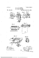
- Fig. 1t is a top plan View of our improved magazine; Fig. 15, a side elevation, and Fig. 16 a section thereof taken on line 3 i 3 of Fig. 15.
- Fig. 17 is a front elevation of the receiver, the magazine being removed and the housing for the upper end thereof closed by a slide shown in section.
- Fig. 18 is a Vertical transverse section of the receiver and 5 magazine, taken on or about on the line 4 4 of Fig. 3.
- Fig. 19 shows the slide or gate for the housing by a top plan view, a side elevation, and a transverse section, respectively.
- Fig. 20 is a rear elevation of the receiver, the mag- 6.
- Fig. 21 is a cross-section taken on or about on the line 5 5 of Fig. 1.
- Fig. 22 is a cross-section taken on the line 6 6 of Fig. 23, 6 which latter shows in side elevation the breech-frame and receiver and the springsupports for the cartridges when the gun is used as a single-loader.
- Fig. 24 is a top plan view of said spring-support detached,and Fig. 7
- This invention relates to that class of bolt and magazine guns which are adapted for use as single-loaders, and has forits object to perfect the loading and firing mechanism and provide suitable safeguards against accidental or 8 premature explosion of the cartridges, and also to improve the construction of the magazine.
- the invention consists in the construction of the bolt-cylinder and the mech 8 anism for manipulating or operating the same in loading and firing; in the construction and combination of safety devices with the bolt-cylinder and bolt; in theconstruction ofa combined trigger-guard and mainspring; in the construction of the trigger-guard and its combination with the magazine, whereby said triggerguard performs the functions of a lock to lockthe magazine in the housing of the breech-frame for use with the receiver; in the construction 9 of the magazine and the cartridgefeeding devices and the combination of the latter with the receiver; and,lastly, in certain other details of construction and combinations of parts, substantially as hereinafter fully described, and as set forth in the claims.
- WVe will first describe the construction of the firing mechanism and the mechanism for manipulating or positioning the same in loading and firing.
- N indicates the gun-stock, of suitable construction to receive the barrel and breech mechanism.
- B indicates the barrel;
- E the breech frame, and E the receiver proper, which has two longitudinal openings or slots diametrically opposite each other, one, E through which the cartridges are introduced from a magazine secured in a housing, E, formed by the breech-frame, and one, E,
- the bolt-cylinder B that contains the bolt or firing-pin D.
- the rear end I) of the bolt-cylinder is in outline polygonal in cross-section.
- the bolt-cylinder B has at its rear end, 0, a helical slot, I), and is provided, as usual, with a locking shoulder or projection, Z1
- the cartridgeextractor F which consists of a flat bar, f, hooked at its outer end to engage the rim of the cartridge and provided with a spring arm, f, at its rear end.
- the bolt-cylinder is closed at its rear end by means of a hollow screw-plug, O.
- a pin or lug, 0, projects into the axial opening in the head of the screw-plug and engages a right'angular groove, (2 at the rear end of the'bolt D, Fig. 12, said bolt being also recessed at that end, as shown at d, and carries a socket, d, that serves as a housing for the actuating'spring d.
- G is the trigger, and g the sear, the upper end of which latter projects through a longitudinal slot, 1/, formed in the bolt-cylinder, which slot at its rear end has a lateral branch. so as to permit the necessary revolving and longitudinal motion of the bolt-cylinder.
- the pin a of the sliding sleeve or nut a On moving the bolt-cylinder back, as described, the pin a of the sliding sleeve or nut a carries the bolt D along, and the rear end of the spring d, coming against the end of the screw-plug (twill be compressed, the bolt being cooked or ready for firing. WVhen the boltcylinder has reached the limit of its rearward motion, the spring-arm F of the ejector F springs out of its groove in front of the sliding nut a, as shown in Fig. 5, to prevent the forward motion of the bolt-cylinder, thus keeping the bolt -spring d compressed.
- the screw-plug G is slightly turned by means of the handle 0 to bring the lug or pin 0 into the lateral branch of the groove d in the rear end of the bolt D, thus locking the ITO latter against forward motion.
- the slot 0 thereof has the lateral branch 0, Fig. 8, above referred to.
- the trigger-guard which, to simplify the gnnlock, is combined with the triggerspring g.
- the guard At its rear end the guard is secured to the lower tang by means of a screw, N, that also secures the upper tang to the stock N.
- the guard At its forward end the guard may also be secured to the tang by a screw when the gun is constructed for use as a single loader.
- the forward end of the guard I has a hooked bearing, i, that passes through a slot in and hooks upon the tang, as more plainly shown in Figs.
- a second hook i, that engages a notch, h", formed in a lip or projection at one end of the magazine H, to support the same in the housing E2
- a support for the cartridges when the gun is used as a single-loader This support consists of two metallic springplates, J J, Figs.
- asupporting-plate, j provided with a spring-arm,j, that lies in a recess or chamber formed in the stock N, said supporting-plate being secured to the breech-frame by a screw, j
- the spring-arm j supports the gnideblock K, that guides the cartridge from the receiver into the breech of the barrel B, as more plainly shown in Figs. 1 and 3.
- the spring-plates J when a magazine is in serted into the housing E, are pushed laterally against the side walls of said housing, and then perlorm the functions of a clamp and assist in holding the magazinein position, and they act as an ejector for the magazine as soon as it is released lrom the trigger-guard, as will be readily understood.
- the open lower end of the housing is closed by a sliding gate, M, Figs. 17, 20, and 22, the edges of which are bent inwardly, so as to form a groove that fits upon a rib, 6', formed on the lateral walls of the housing E of the breechframe.
- the stock N of the gun in front of the housing has two grooved bars, n, secured, as shown in Fig. 21, in its cheeks, into which fit the bent edges of the slide or gate M.
- the magazine H consists of a rectangular casing of the form in cross-section substantially as shown in Fig. 16.
- the diameter of the casing is slightly less than twice the diameter of the cartridges and their rims, so that two tiers of cartridges can be inserted and closely packed, the cartridges of one tier lying tangentially between the cartridges of the other tier, as shown in Figs. 16 and 18. This admits of the feeding of the cartridges to the receiver alternately from both tiers through the medium of the spring h.
- the magazine has open-work sides, and is preferably made of thin sheet metal to make it as light as possible, and in order to give the lateral walls greater strength we form corrugations h h If in the metal, thus providing strengthening-ribs, those If projecting outwardly, while those h project inwardly and serve to guide the'cartridges, thereby reducing the frictional resistance to the motion of the cartridges to a minimum.
- the magazine is supported from the trigger-guard and by the spring-plates J at the rear and forward end, respectively, and when empty may be readily withdrawn by simply pressing back the trigger-guard,which may be made sufficiently elastic for the purpose to disengage thehook z" from the notch h.
- the lateral walls of the magazine for a portion of their length are bent inwardly to form spring-jaws,that prevent the cartridges being ejected from the magazine by the spring h.
- the upper cartridge when lying between the spring-jaws It, will be in a position in which its rim will project into the pathof the boltcylinder B, so that when the latter is moved forward it will remove the cartridge forcibly from between the jaws h and carry it along into the breech.
- the combination with the breech-frame and the bolt cylinder having spiral bearing-faces at its rear end, of an operating handle or lever and a sleeve or nut connected therewith, having corresponding bearing-faces and adapted to slide freely on the rear end ofthe bolt cylinder, substantially as and for the purpose specified.
- the combination with the breech-frame, the bolt-cylinder provided with a spiral slot at its rear end, and the bolt or firing-pin provided with a longitudinal recess at the rear end thereof, of a lever or handle provided with a sleeve bearing mounted and Sliding longitudinally on the rear end of the bolt-cylinder, and a pin pro- -jecting from said bearing through the spiral slot of said cylinder into the recess of the fir ing-pin, substantially as and for the purpose specified.
- the combination with the breech-frame, the bolt-cylinder provided at its rear end with a spiral slot and a springabntmcnt, the bolt or firing-pin provided at the corresponding end with a lougitudinal recess, and an actuating-spring connected at the forward end with the bolt, of a lever or handle provided with a sleeve-bearing mounted and sliding longitudinally on the rear end of the cylinder, and a pin projecting through the spiral slot of said cylinder into the recess of the bolt, whereby the spring is compressed on moving the bolt rearward,substantially as and for the purpose specified.
- the combination with thebreech-frame, thebolt-eylinder provided at its rear end with a spiral slot and a spring-abutment, the bolt or firingpin provided at the corresponding end with a longitudinal recess, and an actuating-spring connected at its forward end with the bolt, of a lever or handle provided with a sleeve-bean ing mounted and sliding longitudinally on the rear end of said cylinder, a pin projecting through the spiral slot in the cylinderinto the recess of the bolt, and a locking device to lock the spring against expansion, substantially as and for the purpose specified.
- the combination with the breech-frame, the bolt-cylindcr provided at its rear end with aspiral slot and a spring abutment, the bolt or firing-pin provided at the corresponding end with a longitudinal recess, and an actualingspring connected at its forward end with the bolt, of a lever or handle provided with a sleeve-bearing mounted and sliding longitudinally on the rear end of the cylinder, a pin projecting through the spiral slot of said cylinder into the recess of the bolt, and a stop operating on the sleeve-bearing to hold it against forward movement on the cylinder, whereby the spring is compressed on moving the bolt rearward and locked against expansion, substantially as and for the purpose specified.
- the combination with the breech-frame open below the receiver, and a magazine adapted to be applied to the frame below said receiver, and provided with a notched projection on its rear Wall,0f a trigger-guard having a yielding bear ing adapted to engage the notch in the magazine projection to support the same at that end, substantially as described.
- the com bination with the breech-frame open below the receiver, and a magazine adapted to be applied to the frame below said receiver, and provided with a notched projection, ofa trigger-guard and trigger-spring combined, and a bearing on said trigger-guard to engage the notched magazine projection, whereby said parts are held in engagement by the stress of the trigger'spring, substantially as described.
Description
(N0, Model.) 7 v 3 Sheets-Sheet 2.
S. 81 K. KRNKA. MAGAZINE FIRE ARM.
Palten'tedfJuly 24; 1888. z zzg zwhf.
f. i J J7 H Moqel 8 Sheets-Sheeiz 3.
'S.-&. K KRNKA. MAGAZINE FIRE ARM.
Patented July 24, 1888.
UNTTED STATES PATENT FFICE.
SILVESTER KRNKA AND KARL KRNKA, OF OBER MIOHLE, NEAR PRAGUE, AUSTRIA-HUNGARY.
MAGAZINE FIRE-ARM.
SPECIFICATION forming part of Letters Patent No. 386,638, dated July 24, 1888.
Application filed November 10, 1887. Serial No. 254,802.
(No model.)
Patented in EngYand May 9, 1887, No. 6,800; in
Anstria'Hnngary August 21, 1887, No. 13,223 and No. 34,833, and October 21, 1887, No. 27,598 and No 49,655; in France September 29, 1887, No. 18li,12l; in Belgium September 29,1887,No. 79,0-14, and in Italy November 12, 1887, XXI, 22,401, XLIV,188.
T aZZ whom it may concern:
Be it known that we, SILVESTER KRNKA and KARL KRNKA, subj ects of the Emperor of Anstria, residing at Ober-Michle, near Prague, in
the Province of Bohemia, in the Empire of Austria-Hungary, have invented certain new and useful Improvements in Magazine Fire- Arms,(for which we have obtained Letters Patent in Austria-Hungary, dated August 21,
(Q 1887, No. 13,223/34,833, and by Letters Pat ent of the same country, dated October 21, 1887, No. 27,598/49,655; in England, dated May 9, 1887, No. 6,800; in France, dated September 29, 1887, No. 186,121; in Belgium, I5 dated September 29, 1887, No. 79,0i4, and in Italy, dated November 12, 1887, Vol. XXI, No. 22,401,and Vol. XLIV, No. 188;) and we do hereby declare the following to be a full, clear, and exact description of the invention, such as 20 will enable others skilled in the art to which it appertains to make and use the same, reference being had to the accompanying drawings, and to letters or figures of reference marked thereon, which form a part of this specification. 2 Referring to the drawings, Figure 1 is alongitudinal section, partly in elevation, of so much of a firearm as is necessary to illustrate our invention. Fig. 2 is a top plan view of the breech portion thereof. Fig. 3 is a view 30 similar to Fig. 1, thebutt being partly broken away, showing the receiver open for the reception of a cartridge. Fig. t is a like view I showing the mechanism in position for firing.
Fig. 5 is a longitudinal transverse section 35 showing the bolt-cylinder withdrawn from the receiver and the tiring-pin or bolt cooked or ready for firing. Fig. 6 is a side elevation of the bolt-cylinder detached. Fig. 7 is a rear end elevation thereof. Fig. 8 is a longitudinal 0 vertical section of the rear end of the bolt-cyl inder, showing the screw-plug in elevation. Fig. 9 is a section taken on the line 1 1 of Fig. 8. Fig. 10 is a view similar to Fig. 8, the screw-plug being shown in section. Fig. 11 is 5 a section taken on the line 2 2 of Fig. 10. Fig. 12 is a side elevation of the bolt or firing-pin. Fig. 13 is a rear end elevation of the handlesleeve. Fig. 1t is a top plan View of our improved magazine; Fig. 15, a side elevation, and Fig. 16 a section thereof taken on line 3 i 3 of Fig. 15. Fig. 17 is a front elevation of the receiver, the magazine being removed and the housing for the upper end thereof closed by a slide shown in section. Fig. 18 is a Vertical transverse section of the receiver and 5 magazine, taken on or about on the line 4 4 of Fig. 3. Fig. 19 shows the slide or gate for the housing by a top plan view, a side elevation, and a transverse section, respectively. Fig. 20 is a rear elevation of the receiver, the mag- 6. azine being removed and the housing therefor closed by a gate, which latter is shown in section. Fig. 21 is a cross-section taken on or about on the line 5 5 of Fig. 1. Fig. 22 is a cross-section taken on the line 6 6 of Fig. 23, 6 which latter shows in side elevation the breech-frame and receiver and the springsupports for the cartridges when the gun is used as a single-loader. Fig. 24 is a top plan view of said spring-support detached,and Fig. 7| 25 shows by a longitudinal section a portion of the receiver and of the upper end of the spring-follower -for the magazine provided with a projection extending into the receiver when the'magazine is empty.
This invention relates to that class of bolt and magazine guns which are adapted for use as single-loaders, and has forits object to perfect the loading and firing mechanism and provide suitable safeguards against accidental or 8 premature explosion of the cartridges, and also to improve the construction of the magazine.
To these ends the invention consists in the construction of the bolt-cylinder and the mech 8 anism for manipulating or operating the same in loading and firing; in the construction and combination of safety devices with the bolt-cylinder and bolt; in theconstruction ofa combined trigger-guard and mainspring; in the construction of the trigger-guard and its combination with the magazine, whereby said triggerguard performs the functions of a lock to lockthe magazine in the housing of the breech-frame for use with the receiver; in the construction 9 of the magazine and the cartridgefeeding devices and the combination of the latter with the receiver; and,lastly, in certain other details of construction and combinations of parts, substantially as hereinafter fully described, and as set forth in the claims.
WVe will first describe the construction of the firing mechanism and the mechanism for manipulating or positioning the same in loading and firing.
As shown in Figs. 1, 2, 3, and 4ofthe drawings, N indicates the gun-stock, of suitable construction to receive the barrel and breech mechanism. B indicates the barrel; E, the breech frame, and E the receiver proper, which has two longitudinal openings or slots diametrically opposite each other, one, E through which the cartridges are introduced from a magazine secured in a housing, E, formed by the breech-frame, and one, E,
i through which the empty shells are ejected, and through which the cartridges are introduced when the gun is used as a single-loader, as shown in Figs. 1 to In the cylindrical bore of the receiver is fitted the bolt-cylinder B, that contains the bolt or firing-pin D. The rear end I) of the bolt-cylinder is in outline polygonal in cross-section. (In the drawings we have shown it as octagonal, though it may have a greater or less number of faces, said faces being arranged spirally relatively to the axis of the cylinder.) On said rear end, I), of the bolt-cylinder B is mounted a sleeve, a, that is also polygonal in erosssection interiorly, the faces or sides corresponding as to their spirality with the like faces of the cylinder.
It is obvious that when the sleeve a is moved in a rectilinear direction either way a partial rotation will be imparted to the bolt-cylinder in one or the other direction on its axis. The sleeve is, to this end, provided with a handle, A, that projects therefrom laterally and downwardly. Heretofore in all guns of this class the handle for manipulating the bolt-cylinder consisted of an arm projecting at right angles or radially from the cylinder. It is obvious that in rapid firing, however, where the gun is not brought from the position of aim, a straight handle or lever is not as conveniently manipulated. To facilitate the manipulation we form the handle portion A at right angles to the handle-arm A, and so as to project downwardly in order to permit a rectilinear push or pull, and to lighten the handle A we make it hollow, as more plainly shown in Figs. 13 and 20.
The bolt-cylinder B has at its rear end, 0, a helical slot, I), and is provided, as usual, with a locking shoulder or projection, Z1 In a longitudinal recess formed in the outer face of the cylinder is fitted the cartridgeextractor F, which consists of a flat bar, f, hooked at its outer end to engage the rim of the cartridge and provided with a spring arm, f, at its rear end. The bolt-cylinder is closed at its rear end by means of a hollow screw-plug, O. in which is also formed a helical slot, 0, provided with a radial or lateral branch, 0, and with a saese thumb-piece, 0 that projects from the head thereof in such a manner as to cover or nearly cover the axial opening in said head-of the screw, to protect the marksman from gases that may escape along the firing-pin or bolt D. As shown in Figs. 4 and 10, a pin or lug, 0, projects into the axial opening in the head of the screw-plug and engages a right'angular groove, (2 at the rear end of the'bolt D, Fig. 12, said bolt being also recessed at that end, as shown at d, and carries a socket, d, that serves as a housing for the actuating'spring d.
When the bolt is properly placed in its boltcylinder B and the latter in the receiver portion of the breech frame, with the sliding handle a on its rear end, the pin a in the sleeve of said handle projects through the radial slot 1) of the bolt-cylinder into the corresponding slot, 0, of the screw-plug and into the recessed portion d of the bolt D, said pin. when the parts are in the position shown in Fig. 1, lying in the forward end of the slots and recess re ferred to, the lockingblock I) being then engaged in the usual recess, e, of the breech-frame to lock the bolt-cylinder in position for firing, as shown in Fig. 2.
It is obvious that by pulling on the handle A in a straight line the sleeve or nut a will impart to the bolt-cylinder a partial revolution from right to left, thereby disengaging the block b from recess 6 and unlocking the boltcylinder. This partial revolution of the boltcylinder is, however, not communicated to the bolt D, for the reason that the upper ilat face of the pin a bears upon the corresponding face of the recess (1 in the bolt, and thus prevents the latter from partaking of such motion.
G is the trigger, and g the sear, the upper end of which latter projects through a longitudinal slot, 1/, formed in the bolt-cylinder, which slot at its rear end has a lateral branch. so as to permit the necessary revolving and longitudinal motion of the bolt-cylinder.
On moving the bolt-cylinder back, as described, the pin a of the sliding sleeve or nut a carries the bolt D along, and the rear end of the spring d, coming against the end of the screw-plug (twill be compressed, the bolt being cooked or ready for firing. WVhen the boltcylinder has reached the limit of its rearward motion, the spring-arm F of the ejector F springs out of its groove in front of the sliding nut a, as shown in Fig. 5, to prevent the forward motion of the bolt-cylinder, thus keeping the bolt -spring d compressed. \Vhen the breech-cylinder is pushed forward and has reached a point Where the spring-arm F fully enters its recess or groove in the bolt-cylinder, the forward end of the housing (1 for the actuating-spring d will be in a position to be engaged by the sear 9, thus maintaining the said spring compressed.
To prevent the accidental discharge of the gun, the screw-plug G is slightly turned by means of the handle 0 to bring the lug or pin 0 into the lateral branch of the groove d in the rear end of the bolt D, thus locking the ITO latter against forward motion. To admit of this partial revolution of the screw-plug, the slot 0 thereof has the lateral branch 0, Fig. 8, above referred to.
It will readily be seen that by means of the described arrangement of the pin a and the slots b and 0 in the bolt-cylinder and screwplug the locking and unlocking of the boltcylinder may be effected by means of the handle A, in the usual manner, and the peculiar construction of the rear end of the said cylinder and the handlesleeve for imparting such partial rotation to said cylinder may be dispensed with. Of course in this case the pin a will have to be made sufficiently strong.
In a gun constructed as described the explosion of the cartridge cannot take place until the bolt-cylinder is fully locked to the brecch-fran'ie, for the reason that the pin a has not then reached the end of the helical slots 1) c in the bolt-cylinder and plug. Consequently, should the trigger be manipulated, the spring (1 would also have to carry said pin to the end of its slot, besides projecting the bolt, or, in other words, complete the rotation of the bolt-cylinder to fully lock it to the breech-frame. It follows that if the bolt is moved at all it is moved but very slowly and gradually in contact with the cartridge.
1 is the trigger-guard, which, to simplify the gnnlock, is combined with the triggerspring g. At its rear end the guard is secured to the lower tang by means of a screw, N, that also secures the upper tang to the stock N. At its forward end the guard may also be secured to the tang by a screw when the gun is constructed for use as a single loader. When, however, the gun is constructed for use both as a single-loader and a repeater, then the forward end of the guard I has a hooked bearing, i, that passes through a slot in and hooks upon the tang, as more plainly shown in Figs. 1 and 2, and on the said bearing is formed a second hook, i, that engages a notch, h", formed in a lip or projection at one end of the magazine H, to support the same in the housing E2 Within the housing E* is arranged a support for the cartridges when the gun is used as a single-loader. This support consists of two metallic springplates, J J, Figs. 22, 23, and 24, secured to asupporting-plate, j, provided with a spring-arm,j, that lies in a recess or chamber formed in the stock N, said supporting-plate being secured to the breech-frame by a screw, j The spring-arm j supports the gnideblock K, that guides the cartridge from the receiver into the breech of the barrel B, as more plainly shown in Figs. 1 and 3.
The spring-plates J, when a magazine is in serted into the housing E, are pushed laterally against the side walls of said housing, and then perlorm the functions of a clamp and assist in holding the magazinein position, and they act as an ejector for the magazine as soon as it is released lrom the trigger-guard, as will be readily understood.
When the gun is used as asingle-loader,the open lower end of the housing is closed by a sliding gate, M, Figs. 17, 20, and 22, the edges of which are bent inwardly, so as to form a groove that fits upon a rib, 6', formed on the lateral walls of the housing E of the breechframe. The stock N of the gun in front of the housing has two grooved bars, n, secured, as shown in Fig. 21, in its cheeks, into which fit the bent edges of the slide or gate M.
The magazine H consists of a rectangular casing of the form in cross-section substantially as shown in Fig. 16. The diameter of the casing is slightly less than twice the diameter of the cartridges and their rims, so that two tiers of cartridges can be inserted and closely packed, the cartridges of one tier lying tangentially between the cartridges of the other tier, as shown in Figs. 16 and 18. This admits of the feeding of the cartridges to the receiver alternately from both tiers through the medium of the spring h.
The magazine has open-work sides, and is preferably made of thin sheet metal to make it as light as possible, and in order to give the lateral walls greater strength we form corrugations h h If in the metal, thus providing strengthening-ribs, those If projecting outwardly, while those h project inwardly and serve to guide the'cartridges, thereby reducing the frictional resistance to the motion of the cartridges to a minimum. As stated hereinbefore, the magazine is supported from the trigger-guard and by the spring-plates J at the rear and forward end, respectively, and when empty may be readily withdrawn by simply pressing back the trigger-guard,which may be made sufficiently elastic for the purpose to disengage thehook z" from the notch h. The lateral walls of the magazine for a portion of their length are bent inwardly to form spring-jaws,that prevent the cartridges being ejected from the magazine by the spring h. The upper cartridge,when lying between the spring-jaws It, will be in a position in which its rim will project into the pathof the boltcylinder B, so that when the latter is moved forward it will remove the cartridge forcibly from between the jaws h and carry it along into the breech.
A great inconvenience in repeaters of this class, especially when used for military purposes, is encountered by the lack of means for ascertaining when the magazine is empty,and in rapid, file, platoon, or general firing the soldier is hardly able to tell whether his magazine is empty or not. This we avoid by forming on the spring h, that feeds the cartridges, or on the follower or cartridge-spoon h ,aprojectionor heel, h, at that end nearest the rear end of the receiver. WVhen the magazine is empty, this heel h projects into the receiver when the bolt-cylinder is drawn back, and the latter can, therefore, not be pushed forward, thus indicating to the marksman that the magazine is empty.
ICO
Inasmuch as we have hereinbefore fully described the operation of the several parts of the gun, it will not be necessary to repeat the same, as this will be readily understood by those conversant with this class of fire-arms.
Having thus fully described our invention, what we claim as new, and desire to secure by Letters Patent, is
1. In a gun of the class described, the combination, with the breech-frame and the bolt cylinder having spiral bearing-faces at its rear end, of an operating handle or lever and a sleeve or nut connected therewith, having corresponding bearing-faces and adapted to slide freely on the rear end ofthe bolt cylinder, substantially as and for the purpose specified.
2. In a gun of the class described, the combination, with the breech-frame, the bolt-cylinder provided with a spiral slot at its rear end, and the bolt or firing-pin provided with a longitudinal recess at the rear end thereof, of a lever or handle provided with a sleeve bearing mounted and Sliding longitudinally on the rear end of the bolt-cylinder, and a pin pro- -jecting from said bearing through the spiral slot of said cylinder into the recess of the fir ing-pin, substantially as and for the purpose specified.
3. In a gun of the class described, the combination,with the breech-frame, the bolt-cylinder provided at its rear end with a spiral slot and a springabntmcnt, the bolt or firing-pin provided at the corresponding end with a lougitudinal recess, and an actuating-spring connected at the forward end with the bolt, of a lever or handle provided with a sleeve-bearing mounted and sliding longitudinally on the rear end of the cylinder, and a pin projecting through the spiral slot of said cylinder into the recess of the bolt, whereby the spring is compressed on moving the bolt rearward,substantially as and for the purpose specified.
4. In a gun of the class described, the combination, with thebreech-frame, thebolt-eylinder provided at its rear end with a spiral slot and a spring-abutment, the bolt or firingpin provided at the corresponding end with a longitudinal recess, and an actuating-spring connected at its forward end with the bolt, of a lever or handle provided with a sleeve-bean ing mounted and sliding longitudinally on the rear end of said cylinder, a pin projecting through the spiral slot in the cylinderinto the recess of the bolt, and a locking device to lock the spring against expansion, substantially as and for the purpose specified.
5. In a gun of the class described, the combination, with the breech-frame, the bolt-cylindcr provided at its rear end with aspiral slot and a spring abutment, the bolt or firing-pin provided at the corresponding end with a longitudinal recess, and an actualingspring connected at its forward end with the bolt, of a lever or handle provided with a sleeve-bearing mounted and sliding longitudinally on the rear end of the cylinder, a pin projecting through the spiral slot of said cylinder into the recess of the bolt, and a stop operating on the sleeve-bearing to hold it against forward movement on the cylinder, whereby the spring is compressed on moving the bolt rearward and locked against expansion, substantially as and for the purpose specified.
6. The combination, substantially as hereinbefore described, with the breech-frame, the bolt-cylinder B, provided at its rear end with a spiral groove, Z), and an interior abutment, the shell-extractor fitted in a groove in the periphery of the cylinder,and having a springextensiomf, the bolt or firingpin, recessed as at d, arranged within the cylinder, and an actuatingspring connected at its forward end with said bolt, of a lever or handle, a bearing-sleeve therefor adapted to slide longitudinally on the bolt-cylinder, and a pin, a, projecting from said sleeve through the slot 1) in the cylinder and into the recess (1 of the belt, for the purposes specified.
7. The combination. substantially as herein described, with the breech -frame, the boltcylinder and its screw plug C, both provided with a spiral groove, 7) a, respectively, the latter groove having a lateral branch, 0 a lug, a, projecting into the opening at the rear end of the plug 0, the bolt or firing-pin, recessed as at d, and provided at its rear end with an angular groove or slot, (1 the actuat' iug'spring secured at its forward end to the bolt, and abutting, when compressed, against the abutment in the cylinder, of the trigger and sear, the latter projecting into the receiver and adapted to engage the forward end of the spring, whereby the bolt may be locked against forward motion by a partial rotation of the screwplug, for the purpose specified.
8. In a gun of the class described, the combination, with the breech-frame open below the receiver, and a magazine adapted to be applied to the frame below said receiver, and provided with a notched projection on its rear Wall,0f a trigger-guard having a yielding bear ing adapted to engage the notch in the magazine projection to support the same at that end, substantially as described.
9. In a gun of the class described, the com bination, with the breech-frame open below the receiver, and a magazine adapted to be applied to the frame below said receiver, and provided with a notched projection, ofa trigger-guard and trigger-spring combined, and a bearing on said trigger-guard to engage the notched magazine projection, whereby said parts are held in engagement by the stress of the trigger'spring, substantially as described.
10. In a gun of the class described, the combination, with the breech-frame open below the receiver,for the attachment of a magazine, and the block K, for guiding the cartridges to the breech, of the spring arm j, provided with a spring, j, operating on the block, and
, two converging spring-plates operating to support the cartridges when the magazine is re- IIO moved and the gun used as a single-loader, In testimony whereof we affix our signatures substantially as described. in presence of two witnesses 11. The con1binati0n,with the breech-frame open below the receiver, the b0lt-cylinder,and SILVESTER KRNKA. a magazine applied below said receiver, of an 1 KARL KRNKA. upwardly-extending stop, h, secured to one end of the spring-actuated follower, for feed- Witnesses: ing the cartridges to the mouth of the maga- ADOLF FISCHER, zine, substantially as and for the purpose speci- ANDREW SToHLL.
Publications (1)
| Publication Number | Publication Date |
|---|---|
| US386638A true US386638A (en) | 1888-07-24 |
Family
ID=2455622
Family Applications (1)
| Application Number | Title | Priority Date | Filing Date |
|---|---|---|---|
| US386638D Expired - Lifetime US386638A (en) | krnka |
Country Status (1)
| Country | Link |
|---|---|
| US (1) | US386638A (en) |
-
0
- US US386638D patent/US386638A/en not_active Expired - Lifetime
Similar Documents
| Publication | Publication Date | Title |
|---|---|---|
| US1291689A (en) | Firearm. | |
| US580935A (en) | ehbets | |
| US663955A (en) | Automatic firearm. | |
| US447836A (en) | maxim | |
| US729413A (en) | Automatic firearm. | |
| US386638A (en) | krnka | |
| US636196A (en) | Automatic gun. | |
| US441673A (en) | Hungary | |
| US589119A (en) | Gas-operated firearm | |
| US710660A (en) | Semi-automatic gun. | |
| US621747A (en) | Gas-operated firearm | |
| US429811A (en) | Nes krag | |
| US437365A (en) | perrna | |
| US245048A (en) | Eduard baethelmes | |
| US611284A (en) | Arthur william savage | |
| US319595A (en) | maxim | |
| US809640A (en) | Gun. | |
| US273131A (en) | nemetz | |
| US486938A (en) | odkolek | |
| US393406A (en) | Hungaey | |
| US475061A (en) | krnka | |
| US854707A (en) | Automatic firearm. | |
| US471362A (en) | schmidt | |
| US415509A (en) | Half to vincent harter | |
| US817764A (en) | Firearm. |