US3828906A - Automatic vending device for packaged containers such as bottles,cans or similar articles - Google Patents
Automatic vending device for packaged containers such as bottles,cans or similar articles Download PDFInfo
- Publication number
- US3828906A US3828906A US00167934A US16793471A US3828906A US 3828906 A US3828906 A US 3828906A US 00167934 A US00167934 A US 00167934A US 16793471 A US16793471 A US 16793471A US 3828906 A US3828906 A US 3828906A
- Authority
- US
- United States
- Prior art keywords
- movement
- portions
- container
- articles
- coin
- Prior art date
- Legal status (The legal status is an assumption and is not a legal conclusion. Google has not performed a legal analysis and makes no representation as to the accuracy of the status listed.)
- Expired - Lifetime
Links
Images


Classifications
-
- G—PHYSICS
- G07—CHECKING-DEVICES
- G07D—HANDLING OF COINS OR VALUABLE PAPERS, e.g. TESTING, SORTING BY DENOMINATIONS, COUNTING, DISPENSING, CHANGING OR DEPOSITING
- G07D5/00—Testing specially adapted to determine the identity or genuineness of coins, e.g. for segregating coins which are unacceptable or alien to a currency
- G07D5/02—Testing the dimensions, e.g. thickness, diameter; Testing the deformation
-
- G—PHYSICS
- G07—CHECKING-DEVICES
- G07F—COIN-FREED OR LIKE APPARATUS
- G07F11/00—Coin-freed apparatus for dispensing, or the like, discrete articles
- G07F11/62—Coin-freed apparatus for dispensing, or the like, discrete articles in which the articles are stored in compartments in fixed receptacles
-
- G—PHYSICS
- G07—CHECKING-DEVICES
- G07F—COIN-FREED OR LIKE APPARATUS
- G07F5/00—Coin-actuated mechanisms; Interlocks
- G07F5/02—Coin-actuated mechanisms; Interlocks actuated mechanically by coins, e.g. by a single coin
- G07F5/06—Coin-actuated mechanisms; Interlocks actuated mechanically by coins, e.g. by a single coin wherein two or more coins of different denominations are required for each transaction
-
- G—PHYSICS
- G07—CHECKING-DEVICES
- G07F—COIN-FREED OR LIKE APPARATUS
- G07F7/00—Mechanisms actuated by objects other than coins to free or to actuate vending, hiring, coin or paper currency dispensing or refunding apparatus
- G07F7/06—Mechanisms actuated by objects other than coins to free or to actuate vending, hiring, coin or paper currency dispensing or refunding apparatus by returnable containers, i.e. reverse vending systems in which a user is rewarded for returning a container that serves as a token of value, e.g. bottles
- G07F7/0609—Mechanisms actuated by objects other than coins to free or to actuate vending, hiring, coin or paper currency dispensing or refunding apparatus by returnable containers, i.e. reverse vending systems in which a user is rewarded for returning a container that serves as a token of value, e.g. bottles by fluid containers, e.g. bottles, cups, gas containers
Definitions
- the specification discloses a vending device adapted for being mounted on top of a container, such as a container for articles, such as bottles, in which the articles are arranged in the container in a predetermined pattern.
- the vending arrangement comprises a cover adapted for being fixed to the open side of the container and having moveable portions thereon for exposing the contents of the container. According to the invention, the moveable portions of the cover are normally locked against movement and are released for exposing a predetermined number of articles for removal under the control of a coin operated mechanism.
- the device for locking the moveable portions of the cover against movement is advantageously in the form of a belt-like element lockingly engaging the portions but being moveable to permit release of the portions singly and for movement a predetermined distance to expose the desired number of articles, for example, one or two.
- the present invention relates to a vending machine for containers, such as bottles, cans, and the like, which comprises in combination a customary transporting case for the container with a lid or cover insertable into said case and adapted to be latched thereto, while said lid or cover together with the compartment-like ar rangement in the transporting case comprises corresponding withdrawal openings with normally closed cover means locked in locking position.
- German Pat. No. 1,242,026 it has be come known with vending machines of the type involved, to provide with flaps or ears the withdrawing openings of a cover device which, together with a customary transporting case, has been combined to form a vending machine for packing containers. It has furthermore become known to lock the flaps or ears which in closing position cover up two withdrawal openings of a box compartment and to do so by means of an appropriate lock. For releasing the flap lock and for opening the individual flaps, keys are provided which are dispensed after coin insertion from an additional key discharging device.
- the coin receiving part is provided with testing devices which exclude the ejection of goods with inserted counterfeit money.
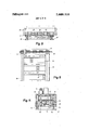
- FIG. 1 illustrates a vending machine according to the invention with longitudinally displaceable shutters for covering the withdrawal openings, the arrangement of FIG. I being shown in partial section as seen from the side.
- FIG. 2 is a top view of the vending machine according to FIG. 1.
- FIG. 3 is a section taken along the line III-III of FIG. 2.
- FIG. 4 is a bottom view of the upper portion of the housing, said view is taken along the line IV-IV of FIG. 1.
- FIG. 5 represents a section taken along the line V-V of FIG. 2.
- FIG. 6 shows a side view of the belt conveyor.
- FIG. 7 shows the top view of the belt conveyor.
- FIG. 8 is a roller shutter on a larger scale seen from above.
- FIG. 9 shows the shutter of FIG. 8 as seen from the front.
- FIG. 10 is a partial section through the upper portion of the housing with a coin tester and seen from the side.
- FIG. 11 represents a section taken along the line XIXI of FIG. 10, said section being taken through the upper portion of the housing.
- FIG. 12 shows a detail of the coin testing device.
- FIG. 13 is a top view of the upper portion of the housing as seen when locking onto the coin testing device.
- FIG. 14 shows an additional detail of the coin testing device.
- FIG. 15 is a view of the dispensing portion of the tested coins.
- FIG. 16 shows a side view partially in section of a vending machine with the flaps covering the withdrawing openings.
- FIG. 17 is a top view of the vending machine.
- FIGS. 18, 19 and 20 respectively illustrate a top view, from view and side view of a lid cover.
- FIG. 21 is a side view of a lid cover adapted to be locked in a locking member.
- FIG. 22 shows a detail for unlocking the flap of FIG. 21.
- the vending machine is characterized primarily by a coin insert which is common to the coverings and is provided with a rotatable or longitudinally displaceable coin slide and with a conveying means adapted to be coupled to the slide or carriage, which conveying means is adapted to be adjusted stepwise when said slide moves.
- the said conveying means which may be in the form of an endless chain, cable or belt, or strand, extends within the cover device in a direction transverse to the path of movement of the coverings.
- Said conveying means forms with the locking members of said covering means a locking system common to said coverings, which locking system is detachable by said conveying means for one covering each or for a plurality of withdrawing openings, after a feeding step of the conveying means.
- the coverings or shutters expediently comprise window shades, slides, or the like, or slides provided with locking means which are longitudinally movable along a row of compartments and above the withdrawing openings.
- the locking mechanisms therefor, as well as a finite belt which is adjustable by means of the coin slide and has its belt surface standing on edge and extending into the path of movement of said slide form the common locking mechanism for the slides of the goods.
- the surface of said finite belt is engaged by locking means and has mounted thereon the unlocking means.
- the locking means comprise cams adapted to engage the belt surface.
- cams are offset relative to each other and are arranged on the top side of the slides for the goods at the pitch of the withdrawal openings while being arranged one behind the other and offset with regard to each other by a distance in conformity with an adjustment of the belt.
- unlocking means there may be employed a window in the band surface, which window is in conformity with the shape of the cam.
- the said windows are respectively located at the end of an adjusting step performed by the belt and is in alignment with the respective cam of a slide for the goods, which latter in its turn passes by the respective window for releasing one or more withdrawal openings.
- the finite belt as well as the central coin insert with the associated coin slide are arranged in a housing provided with guidingpaths for the coin slide and the belt.
- the said housing is detachably connected to a lateral confinement of the cover device which lateral confinement extends transverse to the direction of movement of the slide for the goods.
- the coin insert is provided with devices for checking the inserted coins as to a predetermined number and value, said devices becoming effective during the feeding movement of the coin slide.
- the locking and unlocking device common to the flaps expediently comprises an endless belt adapted to be coupled with the rotary or longitudinally movable coin slide, said belt being adjustable stepwise when the coin slide is being moved.
- the said endless belt extends within the cover device with the band surface standing on edge and transverse to the flaps, said belt, together with the locking means, forming the locking mechanism common to the flaps.
- This locking mechanism is adapted by means of a cutout in the belt surface, which is, in conformity with the locking means for the flaps, detachable or disengageable for one flap each as soon as the cutout reaches a position within the range of a locking means for a flap.
- an endless or finite conveying means for instance, chain means, cable means, belt means, or a stand, which conveying means are adjustable by steps.
- the said endless conveying means with an unlocking member for disengaging the flap latches from the locking elements extends within the cover device in a direction transverse to the flaps.
- the invention provides an endless belt extending in a direction transverse to the flaps and provided with a belt surface standing on edge. This belt has in or on the surface thereof arranged the unlocking element which, following a respective adjusting step, engages a flap latch.
- the vending machine illustrated in FIGS. 1 and 2 is intended for sell ing beverage bottles, for instance, beer bottles, and comprises primarily a commercially customary transporting box 26 of wood or synthetic material and a cover or lid, generally designated 21.
- Bottle boxes or cases 20 of the above mentioned type are standardized, can be piled up and are customarily divided into compartments 22 which permit the withdrawal of the bottles or containers in upward direction only.
- the cover 21 is, as to shape, designed in conformity with the bottle case 20 and is adapted to be placed thereupon or into said case 20.
- Cover 21 When the cover 21 occupies its closing position, it is locked by a fixed jaw 23 and by a resilient latch 24, said elements 23 and 24 being located opposite to each other and engaging cutouts 25 in the wall of the case.
- Cover 21 has a plurality of slides 26 for the goods for closing the withdrawal openings 27 which are formed by the compartments 22 of case 20 within the cover 21.
- Slides 26 respectively extend along a row of compartments 22 over a plurality of withdrawal openings 27 and expediently comprise a flexible strip of material which is adapted to be rolled up, or the slides comprise a train which is composed of flexible individual elements in the manner of a window shade or window cover. It is a matter of course that also rigid slides for goods are employable. As will be evident from the drawings, and in particular, from FIGS.
- the slides 26 which have a handle 28 on one end thereof and are adapted to slide in lateral guiding meas 29 of the cover, have their top side provided with a plurality of cams 30 in conformity with the number of the withdrawal openings 27.
- cams 30 are spaced from each other in conformity with the pitch or distance between the withdrawl openings 27 and are arranged one behind the other while additionally being offset with regard to each other.
- Cover 21 has one side thereof which projects beyond the case 20 widened to form a housing 31 engaging the wall of said case 20.
- Said housing 31 receives those ends of the slide 26 which are located opposite a handle 28 and a coin box 34, and supports a housing upper part 32 of a cap-shaped contour which, by means of a plug lock 33, is adapted to be connected to the cover 21.
- This part 32 contains the devices necessary for the function of the vending machine and, more specifically, the devices for the locking and unlocking of the slide 26 and for the insertion, testing and storing the coins.
- a finite belt 36 which with a belt surface standing on edge or upright extends transverse to the slides 26.
- This belt 36 together with the vertical belt surface extending in the path of movement of the slides 26 and together with the cams 30, engaging said last mentioned belt surface, forms a locking mechanism (FIGS. 8 and 9) which is common to the slides 26.
- belt 36 is guided along a path 38 with oppositely located deviations 37, and more specifically, is guided along the leg of a substantially U- shaped frame 35 of the housing part 32 while resting on the frame protrusions 35 by means of the lower edge of the belt.
- the protrusions 35 are spaced from each other in such a way that the permit an unimpeded passage of the cams 30 (FIGS. 8 and 9).
- the lower edge of belt 36 is provided with a downwardly opening window 41 (FIGS. 6, 9) configurated in conformity with cam 30, and furthermore comprises windows 42 (FIGS. 5 and 6) in the belt surface for engagement by a transporting 5 pawl 43 and a ball latch 44.
- the transporting pawl 43 forms a part of a central coin insert and is rotatably journaled on a bolt 47 connected to a coin slide 45.
- This central coin insert comprises to primarily a coin slide 45 with two coin slots 46 and 46a, as shown in FIGS. 2 and 10.
- the said pawl 43 is under the influence of the thrust of a spring 48.
- the pawl tip facing toward the cutouts or windows 42 is preceded by a slideway 49 which is longitudinally displaceable on frame 35.
- the coin slide 45 itself rests in the housing frame 35 on a horizontal plate 50 and is longitudinally moveably guided within the borders of the frame against a spring force 55 (FIG.
- a web 40 mounted on plate 50 extends through the lower confinement of the slide, as shown in FIG. 3.
- a further ratchet pawl 58 is journaled on a bearing bolt 47 which extends vertically downwardly through a plate window 55. Opposite said pawl 58 in the frame leg there are provided windows 56. A nonillustrated abutment limits the path of the slide.
- levers 60 and 60a respectively, (FIGS. 3 and 4), which have one end thereof that forms a tip to engage coins in an insert station 46, 46a from below so that the coins therein can be lifted into an inclined position facilitatin g the withdrawal of the respective coin.
- a depressible pin 61 which extends centrally through the handle 53.
- Levers 60 and 60a are pivotally journaled on the axis of a shaft 62 and are interconnected by a road 63 which pin 61 abuts for simultaneous actuation of both of the levels.
- Plate 50 is furthermore provided with windows 64 and 640 which lead to the coin box 34.
- the vending machine is equipped with a coin checking device which in response to the actuation of the coin slide checks the coins in the coin inserts 46 and 46a as to a predetermined number thickness and diameter (FIG. 10).
- a coin checking device which in response to the actuation of the coin slide checks the coins in the coin inserts 46 and 46a as to a predetermined number thickness and diameter (FIG. 10).
- each inset station has associated therewith in the housing frame 35 a threaded bolt 65 and 65a which is fixed in the said frame 35 and is adjustable for a desired predetermined number of coins.
- the said bolt 65, a extends vertically from above into the path of movement of the slide 45.
- levers 68, 68a equipped with a feeler member 67, 67a.
- each lever 68, 68a which is located opposite the shaft 66,,66a ends in two hooks 69, 70, and 69a 70a (FIG.4) which are located opposite to each other in spaced relationship to 5 each other.
- the spacing between the hooks respectively corresponds to the dimensions of abutments 72, 72a which are in alignment with a hook spacing and are mounted on a downwardly extending extension on the coin slide 45.
- each lever 75, 75i a is provided with a surface 77 and 77a which faces toward the insert station 46, 46a and which ends in a tip 78 and 78a.
- abutment 79, 79a which is adjustably arranged on the coin slide 45.
- the oppositely located level arm has a hook-shaped extension 80, 80a opposite whichthere is provided a further abutment 81, 81a.
- the insert stations 46, 46a may respectively be provided with an exchangeable insert 83.
- each slide 26 covering a row of compartments is provided with four cams 30.
- These earns 30 are arranged in series on the top side of the slide and spaced from each other by a distance equaling the pitch of the withdrawal openings 27.
- the said cams 30 are offset relative to each other by a distance equaling the belt feed.
- the bolts 65 and 65a which have been adjusted in conformity with the thickness of the predetermined number of coins, will block the longidutinal movement of the coin slide 45 so that it must return to its starting position.
- the levers 68 and 680 which are spring loaded become operative and their feeler members 67, 67a engage from below the insert areas or slots 46 and 46a and permit a pivot movement of the levers 68 and 68a in counter clockwise direction.
- the abutments 72 and 720 which will engage the hooks 69, 70; 69a, 70a limit the further feed of the coin slide 45.
- the check as to the thickness of the coins is accompanied also by a check as to the predetermined number of coins.
- the levers 68 and 68a will in the described manner occupy a locking position and will block the feed ing movement of the coin slide 45.
- the position of the levers 68, 68a remains unchanged.
- the abutments 72 and 72a thus pass unimpededly through the space between the hooks 69, 60a; 70, 70a.
- the surfaces 77, 77a of the levers 75, 75a slide along the circumfernece of the coins and if the diameter of the coin is correct will pivot around the pins 76, 76a into a position which while the sliding movement continues will allow the surfaces 77, 77a of levers 75, 75a to pass by the lever tips 78, 78a and by the extensions 80, 80a on the abutments 79, 79a and 81, 81a set for the predetermined coin diameters. If the coin diameter is too short, the lever tips 78, 78a will abut the associated abutments 79, 79a and will prevent the coin slide 45 from continuing its feeding movement.
- the pawl 58 After receipt of the coins, the pawl 58 successively engaging the windows 56 of frame 35 will prevent the return movement of the coin slide 45.
- the pawl 43 which is likewise moved during the feeding movement of slide 45, which pawl has its tip sliding on panel 49 will after acceptance of the coins by the coin checking mechanism engage the predetermined cutout or window 42 of belt 36 and will adjust said belt against the action of a ball ratchet 44 in the feeding direction by the distance equaling the pitch while the belt window 41 moves into the path of movement of a slide cam 30 and will be in alignment therewith.
- the locking mechanism for the outer slide 26 for the goods is now disengaged as shown in FIG. 2, and said slide 26 is pulled back in the direction of the housing upper part 32 for withdrawing the respective bottle.
- the slides 26 for the goods may also be unlocked for freeing a plurality of discharging openings 27. To this end it is merely necessary to change the arrangement of the cams 30 and/or of the window 41, and to set the slide panel 49 for engagement with the pawl 43 for a respectively necessary belt feed.
- the locking and unlocking mechanism according to the invention may also be used for vending machines of the above mentioned type which is customary manner comprise flaps 92 for closing the withdrawal openings, whereby the sale of a plurality of vessels may be made possible by a single coin insert.
- the cover device which is adapted to be placed upon the transport case or box 20 and which can be locked to said box 20 by the plug lock 33, only the belt 91 standing on edge is designed as an endless belt.
- Belt 91 passes through the guiding path 38 in the same direction of movement while it extends into the path of movement of the flaps 92 which are pivotable about a horizontal pin or shaft 93 and is under the influence of spring means 94.
- the locking mechanism common to the flaps 92 is, as shown in FIGS. 8 to 20, likewise formed by the belt 91 and the flap lock 95 upon which the belt edge acts when the flaps 92 are in their closed position.
- the belt 91 adapted lilewise to be coupled to the coin slide 45 and stepwise adjustable by pawl 43 during the longitudinal movement of belt 91 has its lower belt edge which acts upon the locking members 95 provided with an incline 97 (FIG. 21) which corresponds to the width of a latch tip.
- the remaining structure as well as its mode of operation corresponds to the locking and unlocking mechanism which may, of course, also be equipped with the prescribed coin checking mechanism of the vending machine described in connection with FIGS. 1 and 2.
- the central position 'of the locking and unlocking mechanism in the cover device 90 transverse to the withdrawal flaps is determined merely by the pitch of the compartments of the transport box of the embodiment described above.
- g r M Merely as unlocking mechanism there is provided an endless belt 103 for the flamps 98 illustrated in FIGS. 21 and 22.
- the locking means 99 associated with said flaps 98 are adapted in view of the effect of spring 100 to engage from behind a protrusion 101 of the housing frame 35. These locking means 99 are locked by the protrusion 101 acting customarily as blocking element.
- belt 103 has its belt surface which extends perpendicularly with regard to the path of movement of flaps 98 provided with a cam 102 which during a stepwise advance or feed of belt 103 in the direction indicated by an arrow in FIG. 22 will move into the region of a closed flap 98 and with the inclined end face will move onto the likewise inclined tip of the locking element to thereby adjust the flap locking element 99 so as to disengage the frame protrusion 101.
- the remaining construction of the unlocking mechanism, especially the belt transport by the coin slide is designed in the manner described above and is expediently also equipped with a coin checking device.
- a vending device comprising in combination: a container for articles of substantially the same price to be dispensed and arranged in a predetermined pattern therein, said container being open on one side for access to the articles therein, a cover locked on said open side of the container, said cover comprising portions movable for exposing said articles for removal from said container, locking means common to all said movable portions collectively and normally locking said movable portions against movement, said locking means being movable in steps to release said portions singly for movement to expose articles, means normally preventing movement of said locking means, and coin operated means adapted upon the supply of coins thereto to release said locking means to permit separation thereof for disassembly of said coin operated means and to control the movement of said locking means both in response to actuation of said coin operated means rather than in response to only the coin itself.
- a vending device according to claim 1 in which said locking means and coin operated means are carried by said cover.
- a vending device comprising a container for articles to be dispensed and arranged in a predetermined pattern therein, said container being open on one side for access to the articles therein, a cover locked on said open side of the container, said cover comprising portions moveable for exposing said articles for removal from said container, locking means common to said portions and normally locking said portions against movement, said locking means being moveable in steps to release said portions singly for movement to expose articles, means normally preventing movement of said locking means, and coin operated means adapted upon the supply of coins thereto to release said locking means and to control the movement of said locking means, said locking means being in the form of a beltlike element normally lockingly engaging said portions and moveable in a direction transverse to'the direction of movement of said portions, said element having at least one region therealong forming a release region which releases a said portion for movement when in registration position relative to a respective portion, said coin operated means being operable upon each actuation thereof for actuating said element to move said region thereof from one registration position to another registration position.
- a vending device comprising a container for articles to be dispensed and arranged in a predetermined pattern therein, said container being open on one side for access to the articles therein, a cover locked on said open side of the container, said cover comprising portions moveable for exposing said articles for removal from said container, locking means common to said portions and normally locking said portions against movement, said locking means being moveable in steps to release said portions singly for movement to expose articles, means normally preventing movement of said locking means, and coin operated means adapted upon the supply of coins thereto to release said locking means and to control the movement of said locking means, each of said portion comprising a lock member moveable thereon, said locking means comprising a belt-like element moveable in a direction transverse to the direction of movement of said portions and lockingly engaging said lock members, said element comprising unlocking means at at least one point therealong operable in response to movement of said element to disengage the lock member of the portion nearest thereto from said element.
- a vending comprising a container for articles to be dispensed and arranged in a predetermined pattern therein, said container being open on one side for access to the articles therein, a cover locked on said open side of the container, said cover comprising portions moveable for exposing said articles for removal from said container, locking means common to said portions and normally locking said portions against movement, said locking means being moveable in steps to release said portions singly for movement to expose articles, means normally preventing movement of said locking means, and coin operated means adapted upon the supply of coins thereto to release said locking means and to control the movement of said locking means, said portions being slidable on said container to expose said articles, said portions having abutment means upstand ing therefrom, said locking means comprising a beltlike element moveable in a direction transverse to the direction of movement of said portions and disposed in the path of said abutment means, and at least one notch in said element at least as large as a said abutment means and adapted upon movement of said element to register with a said abut
- a vending device in which the abutment means on each said portion comprise a plurality of abutments distributed thereon in the direction of sliding movement of said portion and spaced in the said direction in conformity with the spacing of the articles in the container the same direction, said abutments being distributed on the respective portion in a direction at right angles to the direction of movement of said portion whereby only a single one of any two consecutive abutments will align with the notch in said element in each adjusted position of the element.
- a vending device comprising a container for articles to be dispensed and arranged in a predetermined pattern therein, said container being open on one side for access to the articles therein a cover locked on said open side of the container, said cover comprising portions moveable for exposing said articles for removal from said container, locking means common to said portions and normally locking said portions against movement, said locking means moveable in steps to release said portions singly for movement to expose articles, means normally preventing movement of said locking means, and coin operated means adapted upon the supply of coins thereto to release said locking means and to control the movement of said locking means, said locking means being in the form of an endless belt moveable in a direction transverse to the direction of movement of said portions, said coin operated means comprising a housing and a coin slide therein, said housing having guide means for said coin slide and for said belt, and said housing being detachably connected to one lateral edge of said cover.
- a vending device in which said cover includes a lateral extension to which said housing is attached, said lateral extension forming a chamber to receive said portions when displaced in article exposing direction and also supporting a coin box to receive coins from said coin slide.
- a vending device in which said coin slide has at least one station to receive coins, said element having holes therein, said coin slide having a pawl engageable with said holes to actuate said element when said coin slide is moved.
- a vending device which includes a plate adjustable in said housing and interposed between said pawal and said element for determining the respective hole engaged by the pawl and thereby controlling the amount of movement of said element.
- a vending device in which the guide means in said housing for said element guides the element in an endless path with the reach of the element facing said portion of the cover being straight, said portion having abutments upstanding therefrom to engage said element, said element having a notch at least as large as a said abutment and adapted to register therewith to permit movement of a said portion, said guide means along the straight reach of said elements comprising protrusions supportingly engaging said element and spaced so as to permit said abutments to pass thereby.
- a vending device in which said coin operated means comprises at least one coin receiving station, and checking means in said station for checking the thickness and diameter of the coins inserted therein, said checking means being operable automatically during coin feeding shift movement.
- a vending device in which said checking means comprises a bolt adjustable axially of said station to engage coins therein, a feeler engageable with said bolt, and a locking lever actuated by said feeler and operable in response to the insertion in said station of an improper thickness of coins to prevent acutation of said coin slide.
- said checking means comprises at least one double-arm pivotally supported feeler lever moveable laterally into said station to feel the diameter of a coin therein, abutment means on said lever and cooperating stationary abutment means, the abutment means on said lever en gaging said stationary abutment means and preventing actuation of said coin slide upon the insertion of a coin of improper diameter in said station.
- a vending device comprising a container for articles to be dispensed and arranged in a predetermined pattern therein, said container being open on one side for access to the articles therein, a cover locked on said open side of the container, said cover comprising portions moveable for exposing said articles for removal from said container, locking means common to said portions and normally locking said portions against movement, said locking means being moveable in steps to release said portions singly for movement to expose articles, means normally preventing movement of said locking means, and coin operated means adapted upon the supply of coins thereto to release said locking means and to control the movement of said locking means, said coin operated means comprising at least one coin receiving station, and checking means in said station for checking the thickness and diameter of the coins inserted therein, said checking means comprising at least one pivotally supported feeler lever moveable laterallly into said station to feel the diameter of a coin therein abutment means on said lever and cooperation stationary abutment means, the abutment means on said lever engaging said stationary abutment means and preventing actuation of
- a vending device in which said portions are in the form of flaps hingedly connected to said cover at the end of the flap opposite to said belt-like element.
- a vending device in which said portions are in the form of flaps hingedly connected at one end to said cover and having the opposite end adjacent said element, said lock members being mounted on the ends of said flaps adjacent said elenext adjacent flap.
Landscapes
- Physics & Mathematics (AREA)
- General Physics & Mathematics (AREA)
- Control Of Vending Devices And Auxiliary Devices For Vending Devices (AREA)
- Vending Machines For Individual Products (AREA)
- Basic Packing Technique (AREA)
Applications Claiming Priority (1)
| Application Number | Priority Date | Filing Date | Title |
|---|---|---|---|
| DE2039151A DE2039151C3 (de) | 1970-08-06 | 1970-08-06 | Selbstverkäufer für Packbehälter, wie Flaschen, Dosen o.dgl |
Publications (1)
| Publication Number | Publication Date |
|---|---|
| US3828906A true US3828906A (en) | 1974-08-13 |
Family
ID=5779052
Family Applications (1)
| Application Number | Title | Priority Date | Filing Date |
|---|---|---|---|
| US00167934A Expired - Lifetime US3828906A (en) | 1970-08-06 | 1971-08-02 | Automatic vending device for packaged containers such as bottles,cans or similar articles |
Country Status (11)
| Country | Link |
|---|---|
| US (1) | US3828906A (de) |
| JP (1) | JPS5219118B1 (de) |
| AT (1) | AT306414B (de) |
| AU (1) | AU3098771A (de) |
| BE (1) | BE771068A (de) |
| CH (1) | CH535464A (de) |
| DE (1) | DE2039151C3 (de) |
| FR (1) | FR2103702A5 (de) |
| GB (1) | GB1347546A (de) |
| NL (1) | NL7108414A (de) |
| ZA (1) | ZA713559B (de) |
Cited By (2)
| Publication number | Priority date | Publication date | Assignee | Title |
|---|---|---|---|---|
| WO2019106492A1 (en) * | 2017-12-02 | 2019-06-06 | Gas Key Cage Sp. Z O. O. | Device for self-service exchange of cylinders, in particular gas cylinders |
| US20210331852A1 (en) * | 2018-09-11 | 2021-10-28 | Soffieria Bertolini S.P.A. | Packaging for the scratchproof transportation of pharmaceutical bottles |
Families Citing this family (6)
| Publication number | Priority date | Publication date | Assignee | Title |
|---|---|---|---|---|
| EP0020804B1 (de) * | 1979-06-25 | 1984-02-01 | Kalevi Takaniemi Tauno | Automat zur Abgabe von Speisen und Getränken |
| FR2537413A1 (fr) * | 1982-12-13 | 1984-06-15 | Chazal Agnes | Distributeur electronique de boissons |
| CA1218439A (en) * | 1983-07-18 | 1987-02-24 | Robert J. Spooner | Self-contained cassette vending machine |
| JPS61157609U (de) * | 1985-03-22 | 1986-09-30 | ||
| DE3719095C1 (de) * | 1987-06-06 | 1989-04-13 | Haendler Metall & Masch | Warenautomat |
| FR2719144B1 (fr) * | 1994-04-22 | 1996-07-05 | Maurice Pisa | Monnayeur mécanique pour distributeur automatique. |
-
1970
- 1970-08-06 DE DE2039151A patent/DE2039151C3/de not_active Expired
- 1970-12-31 JP JP45123790A patent/JPS5219118B1/ja active Pending
-
1971
- 1971-06-02 ZA ZA713559A patent/ZA713559B/xx unknown
- 1971-06-18 NL NL7108414A patent/NL7108414A/xx unknown
- 1971-06-28 CH CH944471A patent/CH535464A/de not_active IP Right Cessation
- 1971-07-08 AU AU30987/71A patent/AU3098771A/en not_active Expired
- 1971-07-20 GB GB3386871A patent/GB1347546A/en not_active Expired
- 1971-07-26 FR FR7127225A patent/FR2103702A5/fr not_active Expired
- 1971-07-28 AT AT659671A patent/AT306414B/de not_active IP Right Cessation
- 1971-08-02 US US00167934A patent/US3828906A/en not_active Expired - Lifetime
- 1971-08-06 BE BE771068A patent/BE771068A/xx unknown
Cited By (3)
| Publication number | Priority date | Publication date | Assignee | Title |
|---|---|---|---|---|
| WO2019106492A1 (en) * | 2017-12-02 | 2019-06-06 | Gas Key Cage Sp. Z O. O. | Device for self-service exchange of cylinders, in particular gas cylinders |
| US20210331852A1 (en) * | 2018-09-11 | 2021-10-28 | Soffieria Bertolini S.P.A. | Packaging for the scratchproof transportation of pharmaceutical bottles |
| US11702267B2 (en) * | 2018-09-11 | 2023-07-18 | Soffieria Bertolini S.P.A. | Packaging for the scratchproof transportation of pharmaceutical bottles |
Also Published As
| Publication number | Publication date |
|---|---|
| DE2039151B2 (de) | 1974-11-28 |
| JPS5219118B1 (de) | 1977-05-26 |
| CH535464A (de) | 1973-03-31 |
| DE2039151C3 (de) | 1975-07-31 |
| AT306414B (de) | 1973-04-10 |
| GB1347546A (en) | 1974-02-27 |
| FR2103702A5 (de) | 1972-04-14 |
| NL7108414A (de) | 1972-02-08 |
| DE2039151A1 (de) | 1972-02-17 |
| SU402246A3 (de) | 1973-10-12 |
| AU3098771A (en) | 1973-01-11 |
| ZA713559B (en) | 1972-01-26 |
| BE771068A (fr) | 1971-12-16 |
Similar Documents
| Publication | Publication Date | Title |
|---|---|---|
| US5529207A (en) | Adjustable retainer system for vending machine storage compartments | |
| US3486658A (en) | Vending machine with removable supply container | |
| US3828906A (en) | Automatic vending device for packaged containers such as bottles,cans or similar articles | |
| US4574980A (en) | Vending machine dispensing mechanism | |
| US6056150A (en) | Apparatus for dispensing tickets, cards and the like from a stack | |
| US2435526A (en) | Multiple compartment vending machine | |
| US4413749A (en) | Newspaper dispensing apparatus and method | |
| US3741464A (en) | Cash box | |
| DE3736263A1 (de) | Maschine zur annahme und ausgabe von banknoten | |
| JP2002008099A (ja) | 包装硬貨投出装置 | |
| JPH03273483A (ja) | 自動販売機 | |
| US3768695A (en) | Method and apparatus for controllably and sequentially dispensing articles, one at a time | |
| US3749281A (en) | Newspaper vending machine | |
| EP1096434B1 (de) | Mediakassette | |
| US4735344A (en) | Device in an automatic vending machine for holding objects dispensed by the latter | |
| US4530444A (en) | Separation device for single copy newspaper vendor | |
| US2215642A (en) | Coin operated vending machine | |
| US3464530A (en) | Coin controlled vending mechanism utilizing a plurality of coins of different denominations | |
| US3685689A (en) | Automatic-delivery apparatus for vending unstackable goods | |
| EP0180358B1 (de) | Blattaufnahmeapparat | |
| US2129322A (en) | Article-dispensing mechanism | |
| US4367826A (en) | Dispensing apparatus and method having abutment stop | |
| JP3857001B2 (ja) | 包装硬貨投出装置 | |
| US5240245A (en) | Container for receiving bank notes in a bank note dispensing device | |
| US1820671A (en) | Vending machine |