US3786302A - Electrostatic lens for cathode ray tubes - Google Patents
Electrostatic lens for cathode ray tubes Download PDFInfo
- Publication number
- US3786302A US3786302A US00148423A US3786302DA US3786302A US 3786302 A US3786302 A US 3786302A US 00148423 A US00148423 A US 00148423A US 3786302D A US3786302D A US 3786302DA US 3786302 A US3786302 A US 3786302A
- Authority
- US
- United States
- Prior art keywords
- lens
- electrode
- potential
- terminal electrodes
- center electrode
- Prior art date
- Legal status (The legal status is an assumption and is not a legal conclusion. Google has not performed a legal analysis and makes no representation as to the accuracy of the status listed.)
- Expired - Lifetime
Links
- 239000003518 caustics Substances 0.000 description 2
- 230000003247 decreasing effect Effects 0.000 description 2
- 230000005686 electrostatic field Effects 0.000 description 2
- 230000003287 optical effect Effects 0.000 description 2
- 241000226585 Antennaria plantaginifolia Species 0.000 description 1
- 238000013459 approach Methods 0.000 description 1
- 230000007423 decrease Effects 0.000 description 1
- 230000003292 diminished effect Effects 0.000 description 1
- 230000000694 effects Effects 0.000 description 1
- 230000005684 electric field Effects 0.000 description 1
- 230000002349 favourable effect Effects 0.000 description 1
- 238000003780 insertion Methods 0.000 description 1
- 230000037431 insertion Effects 0.000 description 1
- 238000012986 modification Methods 0.000 description 1
- 230000004048 modification Effects 0.000 description 1
- 239000007787 solid Substances 0.000 description 1
Images


Classifications
-
- H—ELECTRICITY
- H01—ELECTRIC ELEMENTS
- H01J—ELECTRIC DISCHARGE TUBES OR DISCHARGE LAMPS
- H01J29/00—Details of cathode-ray tubes or of electron-beam tubes of the types covered by group H01J31/00
- H01J29/46—Arrangements of electrodes and associated parts for generating or controlling the ray or beam, e.g. electron-optical arrangement
- H01J29/56—Arrangements for controlling cross-section of ray or beam; Arrangements for correcting aberration of beam, e.g. due to lenses
- H01J29/566—Arrangements for controlling cross-section of ray or beam; Arrangements for correcting aberration of beam, e.g. due to lenses for correcting aberration
-
- H—ELECTRICITY
- H01—ELECTRIC ELEMENTS
- H01J—ELECTRIC DISCHARGE TUBES OR DISCHARGE LAMPS
- H01J29/00—Details of cathode-ray tubes or of electron-beam tubes of the types covered by group H01J31/00
- H01J29/46—Arrangements of electrodes and associated parts for generating or controlling the ray or beam, e.g. electron-optical arrangement
- H01J29/58—Arrangements for focusing or reflecting ray or beam
- H01J29/62—Electrostatic lenses
- H01J29/622—Electrostatic lenses producing fields exhibiting symmetry of revolution
- H01J29/624—Electrostatic lenses producing fields exhibiting symmetry of revolution co-operating with or closely associated to an electron gun
Definitions
- H0lj 29/56 electmdes and The telminal
- References Cited The correcting electrode has a potential applied thereto which is more positive than the potential of UNITED STATES PATENTS the center electrode, and less positive than the poten izi g lg tial of the terminal electrodes.
- y 3,714,504 1/1973 Amboss 315/31 R 8 Claims, 5 Drawing Figures FMENTEBM 1 5 1974 SHEET 1 OF 3 INVENTO'R %erne/ ,V /h
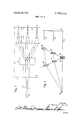
- FIG. 1 is a schematic illustration of the beam path for a cathode ray tube according to the present invention.
- FIG. 2 is an illustration of the electrostatic field and how they influence the beam passing through the tube in a prior art arrangement.
- FIG. 3 is a schematic of the type shown in FIG. 2 illustrating the improvement of the present invention in controlling the path of the beam through the tube.
- FIG. 4 is an analog of the arrangement of FIG. 3 showing how solid lenses affect the path of a beam of light.
- FIG. 5 is a schematic similar to FIG. 3 showing an alternate form of the present invention.
- the present invention relates to an electrostatic lens for a cathode ray tube where the lens is constructed of cylindrical sections.
- the lens includes two terminal electrodes having a high positive potential and a center electrode having a lower or negative potential.
- the center electrode is divided into two sections with a correcting electrode positioned between the two sections.
- the correcting electrode has a potential which is higher than the potential of the center electrode.
- An electrostatic lens is of particular importance in such electron ray tubes in which the amount of caustic, decreases the quality of the tube.
- the beam In an electrostatic cathode ray tube, the beam extends at an angle relative to the axis of the tube after being deflected. Since, however, it must finally hit the target or screen perpendicularly, it is necessary under all circumstances to redirect the beam back into the axial direction after deflection. This must happen between the deflection center and the target with the help of an electrostatic lens.
- the correcting electrode then has a potential applied thereto which is more positive than the potential applied to the parts of the center electrode.
- FIG. 1 shows schematically the beam paths in an electrostatically focused cathode ray tube.
- the beams which come from the cathode 1 form a crossover at a point 2 and pass through the lenses 3 and 4 onto the target 5.
- a deflection device 6 is located between the lenses 3 and 4. Therefore the power of refraction of the lens 4 must be selected to be such a magnitude that all the beams such as illustrated by the numerals 7, 8i and 9 which are deflected by the deflection means 6i hit the target 5 in a perpendicular direction.
- each of the beams 10, 11 and 12 may be followed from their striking points 13, 14 and 15 on the target back through the lenses to determine whether they converge at the same deflection center.
- FIG. 2 a prior art arrangement is shown in which the various electrodes produce the potential fields illustrated by the substantially parallel wavy lines.
- the two terminal electrodes are designated by the numerals l9 and 20. These are maintained at a voltage of approximately 1000 volts.
- the center electrode is designated by the numeral 18 and is maintained at a negative potential of approximately lOO volts. In this arrangement the center electrode is shown as being in three parts though actually each part is electrically coupled to each other as one single unit.
- a saddlepoint area 21 forms so that while the inner beam 22 is deflected in the expected manner (intersecting the axis at 23), the outer beam 24 which extends into proximity with the negative electrode 18 intersects the axis at a point 25 which is much closer to the target.
- This typical fault of the unipotential lens is prevented by the arrangement of the present invention shown in FIG. 3 where the center electrode 18 is divided into two partial electrodes and a less negatively biased electrode such as the ring 26, is positioned between the partial electrodes.
- the advantageous arrangement shown in FIG. 3 causes the beams to converge at the same deflection point 17.
- the center electrode is divided into two parts, and a less negative ring 26 is inserted between the two parts 27 and 28.
- the insertion of the positive electrode 26 in the arrangement of FIG. 3 produces an effect from the individual lenses which has the shape of a double cone.
- the action of the correcting lens in FIG. 3 may be understood by reference to an optical analog shown in FIG. 4.
- the two lenses 30 amd 31 which touch each other represent the lens arrangement for the inner beam, and the remaining lenses 33 through 37 represent respectively the lenses for the beams 32 and 35 which are positioned outwardly from the inner beam 29.
- the power of refraction of a pair of lenses is determined by the following formula:
- the unipotential lens of FIG. 3 preserves the field ahead of the target.
- an electrode arrangement has been utilized ahead of the target which provides a substantially uniform electric field at the target.
- the field strength is essentially less than it would desirably be for a cathode ray tube. Accordingly a second embodiment has been developed in which the field strength ahead of the target reaches substantially higher levels.
- FIG. shows such an arrangement with corrected unipotential lens identified by the numerals 26, 27 and 28.
- the parallel beams 10, ill and 12 meet in one point in the deflection center 6 (by viewing the inverted beam path).
- the main lens 4 has another essential function. It forms a part of the focusing system. Therefore it is an advantage to make the lens sufficiently strong so that its power of refraction is higher than the lens 3. With the distances which are inserted in FIG. 1, the following relation is valid for the enlargement which is to be obtained.
- the arrangement described above not only has the advantage of eliminating the use of a magnetic field in a cathode ray tube, but with a suitable selection of the power of refraction of the lens 4, it can result in an increased resolution.
- the magnetic field is omitted, the size of the target can be caused to increase to the point where it can considerably exceed the dimensions which are common today.
- the deflection means 6 (FIG. I) can be designed as an electrostatic deflection means since the deflection center is located in the field free area of the tube.
- an electrostatic lens comprising:
- first and second terminal electrodes spaced apart within the tube
- said center electrode comprising two parts
- a correction electrode positioned between the two parts of the center electrode.
- An electrostatic lens in accordance with claim 1 wherein, in combination as a main lens with a condenser lens for arrangement in a vidicon, the condenser lens located at the cathode side of the tube and the main lens located at the target side of the tube.
- An electrostatic lens in accordance with claim 4 wherein the power of refraction of the main lens is at least as great as that of the condenser lens and wherein the distances of the main lens as from the target is at least as great as their respective focal lengths.
- An electrostatic lens comprising:
- a third, center electrode including two spaced apart sections for receiving a lower potential applied thereto,
- a fourth electrode as a correction electrode, physically disposed between the two spaced apart sections of the center electrode for receiving a potential applied thereto which is higher than the level symmetrically negative.
Landscapes
- Image-Pickup Tubes, Image-Amplification Tubes, And Storage Tubes (AREA)
- Electron Beam Exposure (AREA)
Applications Claiming Priority (1)
| Application Number | Priority Date | Filing Date | Title |
|---|---|---|---|
| DE19702031486 DE2031486A1 (de) | 1970-06-25 | 1970-06-25 | Elektrostatische Linse, insbesondere für elektrostatisches Vidikon |
Publications (1)
| Publication Number | Publication Date |
|---|---|
| US3786302A true US3786302A (en) | 1974-01-15 |
Family
ID=5774954
Family Applications (1)
| Application Number | Title | Priority Date | Filing Date |
|---|---|---|---|
| US00148423A Expired - Lifetime US3786302A (en) | 1970-06-25 | 1971-06-01 | Electrostatic lens for cathode ray tubes |
Country Status (4)
| Country | Link |
|---|---|
| US (1) | US3786302A (enExample) |
| DE (1) | DE2031486A1 (enExample) |
| FR (1) | FR2099885A5 (enExample) |
| GB (1) | GB1354566A (enExample) |
Cited By (1)
| Publication number | Priority date | Publication date | Assignee | Title |
|---|---|---|---|---|
| US3895253A (en) * | 1973-10-23 | 1975-07-15 | Zenith Radio Corp | Electron gun having extended field electrostatic focus lens |
Families Citing this family (2)
| Publication number | Priority date | Publication date | Assignee | Title |
|---|---|---|---|---|
| JPS6033336B2 (ja) * | 1979-10-31 | 1985-08-02 | 日本ビクター株式会社 | 撮像装置 |
| DE9109629U1 (de) * | 1991-08-02 | 1991-09-19 | Neuwirth, Wolfgang, Prof. Dr., 5000 Köln | Elektrostatisches Fokussierungselement zur Ionen- bzw. Elektronenoptik |
Citations (10)
| Publication number | Priority date | Publication date | Assignee | Title |
|---|---|---|---|---|
| US2911563A (en) * | 1957-04-24 | 1959-11-03 | Westinghouse Electric Corp | Electrostatic lens and deflection system |
| US2983842A (en) * | 1959-06-23 | 1961-05-09 | Zenith Radio Corp | Electrode system |
| US3015752A (en) * | 1959-03-09 | 1962-01-02 | Admiral Corp | Flash-over suppression in cathode ray tubes |
| US3215890A (en) * | 1961-05-22 | 1965-11-02 | Zenith Radio Corp | Electron gun structure for producing an electron beam free of radial velocity components wherein the length of the first non-magnetic cylinder is approximately equal to an integral number of wave lengths of the scallop frequency |
| US3421047A (en) * | 1965-03-17 | 1969-01-07 | Stromberg Carlson Corp | Cathode-ray tube control circuitry |
| US3501668A (en) * | 1968-05-10 | 1970-03-17 | Zenith Radio Corp | Low focus voltage electron gun for cathode-ray tubes |
| US3504225A (en) * | 1965-04-26 | 1970-03-31 | Sony Corp | Electron gun |
| US3651359A (en) * | 1969-04-23 | 1972-03-21 | Sony Corp | Abberation correction of plurality of beams in color cathode ray tube |
| US3714504A (en) * | 1970-10-20 | 1973-01-30 | K Amboss | Electron optic system utilizing a focusing electrode having a more positive voltage than the two adjacent electrodes |
| US3732457A (en) * | 1970-01-30 | 1973-05-08 | Victor Co Ltd | Electrode lens potential arrangement for a post-acceleration picture tube |
-
1970
- 1970-06-25 DE DE19702031486 patent/DE2031486A1/de active Pending
-
1971
- 1971-06-01 US US00148423A patent/US3786302A/en not_active Expired - Lifetime
- 1971-06-24 GB GB2961671A patent/GB1354566A/en not_active Expired
- 1971-06-24 FR FR7123026A patent/FR2099885A5/fr not_active Expired
Patent Citations (10)
| Publication number | Priority date | Publication date | Assignee | Title |
|---|---|---|---|---|
| US2911563A (en) * | 1957-04-24 | 1959-11-03 | Westinghouse Electric Corp | Electrostatic lens and deflection system |
| US3015752A (en) * | 1959-03-09 | 1962-01-02 | Admiral Corp | Flash-over suppression in cathode ray tubes |
| US2983842A (en) * | 1959-06-23 | 1961-05-09 | Zenith Radio Corp | Electrode system |
| US3215890A (en) * | 1961-05-22 | 1965-11-02 | Zenith Radio Corp | Electron gun structure for producing an electron beam free of radial velocity components wherein the length of the first non-magnetic cylinder is approximately equal to an integral number of wave lengths of the scallop frequency |
| US3421047A (en) * | 1965-03-17 | 1969-01-07 | Stromberg Carlson Corp | Cathode-ray tube control circuitry |
| US3504225A (en) * | 1965-04-26 | 1970-03-31 | Sony Corp | Electron gun |
| US3501668A (en) * | 1968-05-10 | 1970-03-17 | Zenith Radio Corp | Low focus voltage electron gun for cathode-ray tubes |
| US3651359A (en) * | 1969-04-23 | 1972-03-21 | Sony Corp | Abberation correction of plurality of beams in color cathode ray tube |
| US3732457A (en) * | 1970-01-30 | 1973-05-08 | Victor Co Ltd | Electrode lens potential arrangement for a post-acceleration picture tube |
| US3714504A (en) * | 1970-10-20 | 1973-01-30 | K Amboss | Electron optic system utilizing a focusing electrode having a more positive voltage than the two adjacent electrodes |
Cited By (1)
| Publication number | Priority date | Publication date | Assignee | Title |
|---|---|---|---|---|
| US3895253A (en) * | 1973-10-23 | 1975-07-15 | Zenith Radio Corp | Electron gun having extended field electrostatic focus lens |
Also Published As
| Publication number | Publication date |
|---|---|
| DE2031486A1 (de) | 1971-12-30 |
| FR2099885A5 (enExample) | 1972-03-17 |
| GB1354566A (en) | 1974-06-05 |
Similar Documents
| Publication | Publication Date | Title |
|---|---|---|
| KR950007682B1 (ko) | 음극선관 | |
| KR0173722B1 (ko) | 컬러음극선관 | |
| US3952227A (en) | Cathode-ray tube having electrostatic focusing and electrostatic deflection in one lens | |
| US3023336A (en) | Cathode ray tube having post acceleration | |
| US4052643A (en) | Electron guns for use in cathode ray tubes | |
| US3786302A (en) | Electrostatic lens for cathode ray tubes | |
| US3852637A (en) | Electron gun structure with unipotential and bipotential lens | |
| JPH0831337A (ja) | カラー陰極線管用電子銃 | |
| US3863091A (en) | Electron gun assembly with improved unitary lens system | |
| US5434471A (en) | Electron gun having focusing electrode and anode with a plurality of straight line segments | |
| KR960016431B1 (ko) | 음극선관용 전자총 | |
| US3036238A (en) | High resolution c.r. tube | |
| KR930009465B1 (ko) | 음극선관용 전자총 | |
| US6841924B1 (en) | Low-voltage high-resolution einzel gun | |
| US4659964A (en) | Display tube | |
| US3870002A (en) | Television camera tube with three electrode focusing lens | |
| KR950004853Y1 (ko) | 다단집속형 전자총 | |
| KR900002903B1 (ko) | 칼라음극선관용 전자총 | |
| KR950001224Y1 (ko) | 다단집속형 전자총 | |
| JPH0118536B2 (enExample) | ||
| GB783305A (en) | Improvements in or relating to cathode-ray tubes for reproducing coloured televisionimages | |
| US3678317A (en) | Electron lens for convergence of plurality of beams | |
| JPS58818B2 (ja) | カラ−受像管 | |
| JP3074179B2 (ja) | 陰極線管 | |
| US2225099A (en) | Cathode-ray tube |