US3772633A - Multiple service extension cord - Google Patents
Multiple service extension cord Download PDFInfo
- Publication number
- US3772633A US3772633A US00235972A US3772633DA US3772633A US 3772633 A US3772633 A US 3772633A US 00235972 A US00235972 A US 00235972A US 3772633D A US3772633D A US 3772633DA US 3772633 A US3772633 A US 3772633A
- Authority
- US
- United States
- Prior art keywords
- multiple service
- contact elements
- pair
- male
- reduction
- Prior art date
- Legal status (The legal status is an assumption and is not a legal conclusion. Google has not performed a legal analysis and makes no representation as to the accuracy of the status listed.)
- Expired - Lifetime
Links
- 239000003989 dielectric material Substances 0.000 claims abstract description 5
- 239000002184 metal Substances 0.000 claims abstract description 4
- 239000004020 conductor Substances 0.000 claims description 2
- 238000010276 construction Methods 0.000 abstract description 4
- 238000004519 manufacturing process Methods 0.000 description 3
- 239000000463 material Substances 0.000 description 2
- 230000037431 insertion Effects 0.000 description 1
- 238000003780 insertion Methods 0.000 description 1
- 238000009413 insulation Methods 0.000 description 1
- 230000002452 interceptive effect Effects 0.000 description 1
- WABPQHHGFIMREM-UHFFFAOYSA-N lead(0) Chemical compound [Pb] WABPQHHGFIMREM-UHFFFAOYSA-N 0.000 description 1
Images
Classifications
-
- H—ELECTRICITY
- H01—ELECTRIC ELEMENTS
- H01R—ELECTRICALLY-CONDUCTIVE CONNECTIONS; STRUCTURAL ASSOCIATIONS OF A PLURALITY OF MUTUALLY-INSULATED ELECTRICAL CONNECTING ELEMENTS; COUPLING DEVICES; CURRENT COLLECTORS
- H01R25/00—Coupling parts adapted for simultaneous co-operation with two or more identical counterparts, e.g. for distributing energy to two or more circuits
- H01R25/003—Coupling parts adapted for simultaneous co-operation with two or more identical counterparts, e.g. for distributing energy to two or more circuits the coupling part being secured only to wires or cables
-
- Y—GENERAL TAGGING OF NEW TECHNOLOGICAL DEVELOPMENTS; GENERAL TAGGING OF CROSS-SECTIONAL TECHNOLOGIES SPANNING OVER SEVERAL SECTIONS OF THE IPC; TECHNICAL SUBJECTS COVERED BY FORMER USPC CROSS-REFERENCE ART COLLECTIONS [XRACs] AND DIGESTS
- Y10—TECHNICAL SUBJECTS COVERED BY FORMER USPC
- Y10T—TECHNICAL SUBJECTS COVERED BY FORMER US CLASSIFICATION
- Y10T428/00—Stock material or miscellaneous articles
- Y10T428/12—All metal or with adjacent metals
- Y10T428/12361—All metal or with adjacent metals having aperture or cut
- Y10T428/12368—Struck-out portion type
Definitions
- the device comprises a conventional multiple service extension cord in which the multiple service tap is reduced to a minimum size of a small rectangular block. Further savings are accomplished by providing a single pair of contact elements for receiving a pair of male contact plug elements from opposite directions.
- the contact elements are designed so that they can be stamped from a single piece of stock requiring no assembly operations.
- the transverse passageways for receiving the male contact elements are offset so that one pair of contact elements enter a passageway which leads below the service contacts and the opposite pair of male contacts enter a passageway which is offset to swing above the contacts. This results in a reduction in size. Since the plastic dielectric material from which the service tap is molded is fairly expensive, the reduction in weight results in a considerable saving in costs. Furthermore, the contact elements also are reduced to an irreducible minimum of contact areas. This is also an expensive metal and any reduction here also results in a cost reduction.
- the rectangular block construction permits safety in that the block can be stepped on without injuring the parts.
- the principal object of the present invention is to provide a multiple service tap for an extension cord in which the body of the service tap and the metallic contact elements are reduced to a minimum.
- Another object of the present invention is to provide a multiple service tap having a Single pair of novel contact elements adapted to receive a plurality of male contact elements from opposite directions.
- a further object of the present invention is to provide a multiple service tap in which a single contact element receives a plurality of male contact elements one above and one below in offset relation to save space.
- Another object of the present invention is to provide a multiple service tap in which the metallic contact elements can be stamped from sheet stock requiring no further assembly operations.
- a further object of the present invention is to provide a multiple service tap for an extension cord which is simple in construction and easy and economical to manufacture and assemble.
- Multiple service extension cords conventionally comprise a male contact plug having a pair of contacts which are insertable in a wall receptacle.
- An extension cord of suitable length extends from the male contact plug.
- a multiple service tap At the outer end of the extension cord is a multiple service tap.
- This is a female type element designed to receive one or more male contact plugs usually attached to lamps or other electrical devices.
- the multiple service tap is designed to receive the male contact elements on different faces of the tap and suitable female contact elements must be provided for receiving the male contact elements and for providing the continuity in the electrical connection. Therefore. most multiple service taps are fairly bulky and comparatively expensive to manufacture.
- the present invention is designed to provide a multiple service tap which reduces its bulk to a minimum size and reduces the metallic parts to a minimum. Assembly operations are eliminated and the cost is greatly reduced.
- the multiple service tap of the present invention is designed in the form of a flat rectangular element so that it will not be damaged if stepped on accidentally.
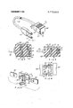
- FIG. 1 is a perspective view of a multiple service tap and extension cord embodying the present invention.
- FIG. 2 is an enlarged section taken on line 2-2 on FIG. 1.
- FIG. 3 is a similar section taken on line 3-3 on FIG.
- FIG. 4 is a plan view showing the contact between a pair of male contact elements and the multiple service contacts with the body of the multiple service tap removed.
- FIG. 5 is an exploded view showing the position of the male contacts with relation to the multiple service contact.
- the usual multiple service extension cord comprises a male contact element 10 having the usual pair of electrical contacts 11 for insertion into a wall receptacle. Extending from the male contact element 10 is the extension cord 12 of a suitable length. Attached to the opposite end of the extension cord is the multiple service tap 13. While any type of dielectric material suitable for the purpose can be used, it is contemplated that the various body parts such as the con tact element 10, the insulation cover for the double cord 12 and the body of the multiple servicejtap 13 all be molded of a plastic material.
- each contact element comprises a flat rectangular body portion 14 having a strap 15 extruded outwardly from the body of the contact element 14 in transverse position adjacent one side of the center.
- a second strap 16 is similarly extruded in the opposite direction at the other side of the center strip 17.
- An integral tongue 18 extends at right angles from the strip 15 out towards the edge of the contact element 14 and a similar tongue 19 extends from the straps 16.
- the tongue portions 18 and 19 form resilient contact portions in parallel spaced relation to the body portion 14.
- the body portion 14 is also provided adjacent one edge towards the center with an integral extending lug 20 which may be bent at right angles to the body portion and is provided with an annular body portion 21 adapted to receive the bared ends of a cord lead connection and to be wrapped around it in a conventional manner.
- a male contact element 22 enters from the left and can be pushed in the space between the tongue 18 and the body portion 14 and slid between the ends of the strap portion 15 to make electrical contact with the element.
- a second male contact element 23 may be moved into contact with the element 14 from the opposite direction.
- the element 23 is offset from the element 22 so that it slides on to the other side of the body portion 14 and between the resilient member 19 and the body portion.
- the male contact elements 22 and 23 both make contact with the contact portion 14 in identical manner but on opposite sides thereof. Therefore, they can be pushed into position as far as they must go without interfering with each other.
- FIG. 4 This arrangement is more clearly demonstrated in FIG. 4.
- the contact elements 14 are duplicates of the one shown in FIG. 5 and are properly positioned in spaced parallel relation. It will be seen that the male tap 24 will slide its male contact elements 22 above the body portions 14 and beneath the resilient member 18 into the straps 15. Also the male contact element 25 will push its contact members 23 below the body portions 14 and between the resilient members 19 and straps 16. Note that the male contact elements 22 and 23 slide by each other without interference, each making the necessary full physical electrical contact with the element 14.
- the electrical cord lead wire 12 is provided with a pair of bared ends which are locked in the portions 22 of the contact elements 14 as shown in FIG. 3.
- the body portion 26 is now molded around the assembly illustrated in FIG. 3 in the usual manner.
- the body portion 26 is now provided with a pair of spaced passageways 27 leading from one face to one side of the contact elements 14 and a pair of spaced parallel passageways 28 leading to the other side of the contact elements 14 so that they will receive the male contact elements in a manner shown in FIG. 4.
- a small pair of contact elements can therefore receive two pairs of small contact plugs thus enabling the reduction in size of the multiple service tap together with a reduction in size of costly material of the contact elements per se.
- the positioning of the contact elements, the cord lead connection and the passageways from opposite directions, permit a great reduction in the size of the body portion 26.
- the overall structure results in a small rectangular body portion which is only slightly more than an inch in length, approximately inch in width and less than inch in thickness.
- the resultant multiple service tap is light in weight yet sturdy, requires a minimum of assembly operations and is extremely economical to manufacture.
- a multiple service extension cord comprising a length of two conductor electrical cord, a male connector at one end of said cord, a multiple service connector at the other end, said multiple service connector comprising an oblong block of dielectric material, said block having a pair of spaced parallel openings extending inwardly from opposite sides of said block, said pairs of openings being contiguously offset from each other, and means in said block at each pair of contiguous openings for electrically contacting a male contact element inserted in either opening, each of said means being electrically connected to one of said electrical cords, said means comprising a flat rectangular conductive metal member having a T-shaped portion stamped therefrom and extending in spaced parallel relation thereto to receive a male contact element therebetween, said member having a second T-shaped portion on the opposite side from said T-shaped portions.
- each of said means comprises an integral onepiece member.
- each of said means is provided with an integral U-shaped portion for electrically connecting to one of said cords.
- each of said means is provided with an integral U-shaped portion for electrically connecting to one of said cords.
Landscapes
- Connector Housings Or Holding Contact Members (AREA)
Abstract
The device comprises a conventional multiple service extension cord in which the multiple service tap is reduced to a minimum size of a small rectangular block. Further savings are accomplished by providing a single pair of contact elements for receiving a pair of male contact plug elements from opposite directions. The contact elements are designed so that they can be stamped from a single piece of stock requiring no assembly operations. The transverse passageways for receiving the male contact elements are offset so that one pair of contact elements enter a passageway which leads below the service contacts and the opposite pair of male contacts enter a passageway which is offset to swing above the contacts. This results in a reduction in size. Since the plastic dielectric material from which the service tap is molded is fairly expensive, the reduction in weight results in a considerable saving in costs. Furthermore, the contact elements also are reduced to an irreducible minimum of contact areas. This is also an expensive metal and any reduction here also results in a cost reduction. The rectangular block construction permits safety in that the block can be stepped on without injuring the parts.
Description
United States Patent Danesi 5] Nov. 13, 1973 MULTIPLE SERVICE EXTENSION CORD [22 Filed: Mar. 26, 1972' [21] Appl. No.: 235,972
[52] US. Cl 339/28, 29/193, 339/32 R, 339/154 R, 339/164 R, 339/204 R, 339/218 R [51] Int. Cl. H01r 11/18, HOlr 13/54 [58] Field of Search 339/19, 22, 28, 29, 339/31-33, 65, 66, 75, 76, 95,176,154,166, 198.6, 174, 204, 205, 218, 241, 248, 252, 256, 258
[56] References Cited UNITED STATES PATENTS 3,083,344 3/1963 Long 339/31 R 3,388,976 6/1968 Danesi 29/193 R 3,199,068 8/1965 Neenan..... 339/248 X 3,005,179 10/1961 I-Iolt 339/159 C FOREIGN PATENTS OR APPLICATIONS 550,848 12/1957 Canada 339/157 C 944,925 11/1948 France 339/154 A 1,574,163 7/1969 France 339/198 N Primary ExaminerMarvin A. Champion Assistant Examiner-Terrell P. Lewis Attorney-Max Schwartz [57] ABSTRACT The device comprises a conventional multiple service extension cord in which the multiple service tap is reduced to a minimum size of a small rectangular block. Further savings are accomplished by providing a single pair of contact elements for receiving a pair of male contact plug elements from opposite directions. The contact elements are designed so that they can be stamped from a single piece of stock requiring no assembly operations. The transverse passageways for receiving the male contact elements are offset so that one pair of contact elements enter a passageway which leads below the service contacts and the opposite pair of male contacts enter a passageway which is offset to swing above the contacts. This results in a reduction in size. Since the plastic dielectric material from which the service tap is molded is fairly expensive, the reduction in weight results in a considerable saving in costs. Furthermore, the contact elements also are reduced to an irreducible minimum of contact areas. This is also an expensive metal and any reduction here also results in a cost reduction. The rectangular block construction permits safety in that the block can be stepped on without injuring the parts.
4 Claims, 5 Drawing Figures PAIENTEI] NIH I 3 I975 ull MULTIPLE SERVICE EXTENSION CORD My present invention relates to the electrical art and more particularly to a novel construction of an extension cord with a multiple service tap.
The principal object of the present invention is to provide a multiple service tap for an extension cord in which the body of the service tap and the metallic contact elements are reduced to a minimum.
Another object of the present invention is to provide a multiple service tap having a Single pair of novel contact elements adapted to receive a plurality of male contact elements from opposite directions.
A further object of the present invention is to provide a multiple service tap in which a single contact element receives a plurality of male contact elements one above and one below in offset relation to save space.
Another object of the present invention is to provide a multiple service tap in which the metallic contact elements can be stamped from sheet stock requiring no further assembly operations.
A further object of the present invention is to provide a multiple service tap for an extension cord which is simple in construction and easy and economical to manufacture and assemble.
With the above and other objects and advantageous features in view, my invention consists of a novel arrangement of parts more fully disclosed in the detailed description following in conjunction with the accompanying drawings, and more particularly defined in the appended claims.
Multiple service extension cords conventionally comprise a male contact plug having a pair of contacts which are insertable in a wall receptacle. An extension cord of suitable length extends from the male contact plug. At the outer end of the extension cord is a multiple service tap. This isa female type element designed to receive one or more male contact plugs usually attached to lamps or other electrical devices. The multiple service tap is designed to receive the male contact elements on different faces of the tap and suitable female contact elements must be provided for receiving the male contact elements and for providing the continuity in the electrical connection. Therefore. most multiple service taps are fairly bulky and comparatively expensive to manufacture. The present invention is designed to provide a multiple service tap which reduces its bulk to a minimum size and reduces the metallic parts to a minimum. Assembly operations are eliminated and the cost is greatly reduced. Furthermore, the multiple service tap of the present invention is designed in the form of a flat rectangular element so that it will not be damaged if stepped on accidentally.
In the drawings,
FIG. 1 is a perspective view of a multiple service tap and extension cord embodying the present invention.
FIG. 2 is an enlarged section taken on line 2-2 on FIG. 1.
FIG. 3 is a similar section taken on line 3-3 on FIG.
FIG. 4 is a plan view showing the contact between a pair of male contact elements and the multiple service contacts with the body of the multiple service tap removed.
FIG. 5 is an exploded view showing the position of the male contacts with relation to the multiple service contact.
Referring more in detail to the drawings illustrating my invention, the usual multiple service extension cord comprises a male contact element 10 having the usual pair of electrical contacts 11 for insertion into a wall receptacle. Extending from the male contact element 10 is the extension cord 12 of a suitable length. Attached to the opposite end of the extension cord is the multiple service tap 13. While any type of dielectric material suitable for the purpose can be used, it is contemplated that the various body parts such as the con tact element 10, the insulation cover for the double cord 12 and the body of the multiple servicejtap 13 all be molded of a plastic material.
Now referring to FIG. 5, I provide a pair of female contact elements to be mounted in the multiple service tap 13. Each contact element comprises a flat rectangular body portion 14 having a strap 15 extruded outwardly from the body of the contact element 14 in transverse position adjacent one side of the center. A second strap 16 is similarly extruded in the opposite direction at the other side of the center strip 17. An integral tongue 18 extends at right angles from the strip 15 out towards the edge of the contact element 14 and a similar tongue 19 extends from the straps 16. The tongue portions 18 and 19 form resilient contact portions in parallel spaced relation to the body portion 14. The body portion 14 is also provided adjacent one edge towards the center with an integral extending lug 20 which may be bent at right angles to the body portion and is provided with an annular body portion 21 adapted to receive the bared ends of a cord lead connection and to be wrapped around it in a conventional manner.
As can be seen in FIG. 5, a male contact element 22 enters from the left and can be pushed in the space between the tongue 18 and the body portion 14 and slid between the ends of the strap portion 15 to make electrical contact with the element. Simultaneously a second male contact element 23 may be moved into contact with the element 14 from the opposite direction. However, the element 23 is offset from the element 22 so that it slides on to the other side of the body portion 14 and between the resilient member 19 and the body portion. Thus the male contact elements 22 and 23 both make contact with the contact portion 14 in identical manner but on opposite sides thereof. Therefore, they can be pushed into position as far as they must go without interfering with each other.
This arrangement is more clearly demonstrated in FIG. 4. In this figure the contact elements 14 are duplicates of the one shown in FIG. 5 and are properly positioned in spaced parallel relation. It will be seen that the male tap 24 will slide its male contact elements 22 above the body portions 14 and beneath the resilient member 18 into the straps 15. Also the male contact element 25 will push its contact members 23 below the body portions 14 and between the resilient members 19 and straps 16. Note that the male contact elements 22 and 23 slide by each other without interference, each making the necessary full physical electrical contact with the element 14.
In assembly, the electrical cord lead wire 12 is provided with a pair of bared ends which are locked in the portions 22 of the contact elements 14 as shown in FIG. 3. The body portion 26 is now molded around the assembly illustrated in FIG. 3 in the usual manner. By providing inserts in a conventional mold, the body portion 26 is now provided with a pair of spaced passageways 27 leading from one face to one side of the contact elements 14 and a pair of spaced parallel passageways 28 leading to the other side of the contact elements 14 so that they will receive the male contact elements in a manner shown in FIG. 4.
A small pair of contact elements can therefore receive two pairs of small contact plugs thus enabling the reduction in size of the multiple service tap together with a reduction in size of costly material of the contact elements per se. The positioning of the contact elements, the cord lead connection and the passageways from opposite directions, permit a great reduction in the size of the body portion 26. The overall structure results in a small rectangular body portion which is only slightly more than an inch in length, approximately inch in width and less than inch in thickness. The resultant multiple service tap is light in weight yet sturdy, requires a minimum of assembly operations and is extremely economical to manufacture. Other advantages of the present invention will be readily apparent to a person skilled in the art.
I claim:
1. A multiple service extension cord comprising a length of two conductor electrical cord, a male connector at one end of said cord, a multiple service connector at the other end, said multiple service connector comprising an oblong block of dielectric material, said block having a pair of spaced parallel openings extending inwardly from opposite sides of said block, said pairs of openings being contiguously offset from each other, and means in said block at each pair of contiguous openings for electrically contacting a male contact element inserted in either opening, each of said means being electrically connected to one of said electrical cords, said means comprising a flat rectangular conductive metal member having a T-shaped portion stamped therefrom and extending in spaced parallel relation thereto to receive a male contact element therebetween, said member having a second T-shaped portion on the opposite side from said T-shaped portions.
2. A multiple service connector as in claim 1, wherein each of said means comprises an integral onepiece member.
3. A multiple service connector as in claim 1, wherein each of said means is provided with an integral U-shaped portion for electrically connecting to one of said cords.
4. A multiple service connector as in claim 2, wherein each of said means is provided with an integral U-shaped portion for electrically connecting to one of said cords.
Claims (4)
1. A multiple service extension cord comprising a length of two conductor electrical cord, a male connector at one end of said cord, a multiple service connector at the other end, said multiple service connector comprising an oblong block of dielectric material, said block having a pair of spaced parallel openings extending inwardly from opposite sides of said block, said pairs of openings being contiguously offset from each other, and means in said block at each pair of contiguous openings for electrically contacting a male contact element inserted in either opening, each of said means being electrically connected to one of said electrical cords, said means comprising a flat rectangular conductive metal member having a T-shaped portion stamped therefrom and extending in spaced parallel relation thereto to receive a male contact element therebetween, said member having a second T-shaped portion on the opposite side from said T-shaped portions.
2. A multiple service connector as in claim 1, wherein each of said means comprises an integral one-piece member.
3. A multiple service connector as in claim 1, wherein each of said means is provided with an integral U-shaped portion for electrically connecting to one of said cords.
4. A multiple service connector as in claim 2, wherein each of said means is provided with an integral U-shaped portion for electrically connecting to one of said cords.
Applications Claiming Priority (1)
| Application Number | Priority Date | Filing Date | Title |
|---|---|---|---|
| US23597272A | 1972-03-20 | 1972-03-20 |
Publications (1)
| Publication Number | Publication Date |
|---|---|
| US3772633A true US3772633A (en) | 1973-11-13 |
Family
ID=22887610
Family Applications (1)
| Application Number | Title | Priority Date | Filing Date |
|---|---|---|---|
| US00235972A Expired - Lifetime US3772633A (en) | 1972-03-20 | 1972-03-20 | Multiple service extension cord |
Country Status (1)
| Country | Link |
|---|---|
| US (1) | US3772633A (en) |
Cited By (5)
| Publication number | Priority date | Publication date | Assignee | Title |
|---|---|---|---|---|
| US3998517A (en) * | 1975-06-20 | 1976-12-21 | International Telephone And Telegraph Corporation | Multiple outlet electrical connector |
| US4650270A (en) * | 1985-05-13 | 1987-03-17 | Hosiden Electronics Co., Ltd. | Shielding connector |
| US4707043A (en) * | 1986-11-03 | 1987-11-17 | Reed Charlie C | Electrical connector |
| US4768965A (en) * | 1987-01-08 | 1988-09-06 | Chang Yen C | Electrical connector with selective receptacles |
| USD362229S (en) | 1993-06-16 | 1995-09-12 | Woods Industries, Inc. | Outlet, switched extension cord |
Citations (7)
| Publication number | Priority date | Publication date | Assignee | Title |
|---|---|---|---|---|
| FR944925A (en) * | 1947-04-09 | 1949-04-20 | Electrical connection device | |
| CA550848A (en) * | 1957-12-31 | B. Weiss Thomas | Electric plug receptacle | |
| US3005179A (en) * | 1959-07-28 | 1961-10-17 | Bri Son Electronics Inc | Multiple electrical outlet |
| US3083344A (en) * | 1959-11-13 | 1963-03-26 | Albert C Long | Combination electric plug and socket |
| US3199068A (en) * | 1961-12-12 | 1965-08-03 | Thomas & Betts Corp | Multiple terminal mounting device |
| US3388976A (en) * | 1965-10-22 | 1968-06-18 | Cable Electric Products Inc | Female molded-on electrical connector |
| FR1574163A (en) * | 1968-05-16 | 1969-07-11 |
-
1972
- 1972-03-20 US US00235972A patent/US3772633A/en not_active Expired - Lifetime
Patent Citations (7)
| Publication number | Priority date | Publication date | Assignee | Title |
|---|---|---|---|---|
| CA550848A (en) * | 1957-12-31 | B. Weiss Thomas | Electric plug receptacle | |
| FR944925A (en) * | 1947-04-09 | 1949-04-20 | Electrical connection device | |
| US3005179A (en) * | 1959-07-28 | 1961-10-17 | Bri Son Electronics Inc | Multiple electrical outlet |
| US3083344A (en) * | 1959-11-13 | 1963-03-26 | Albert C Long | Combination electric plug and socket |
| US3199068A (en) * | 1961-12-12 | 1965-08-03 | Thomas & Betts Corp | Multiple terminal mounting device |
| US3388976A (en) * | 1965-10-22 | 1968-06-18 | Cable Electric Products Inc | Female molded-on electrical connector |
| FR1574163A (en) * | 1968-05-16 | 1969-07-11 |
Cited By (5)
| Publication number | Priority date | Publication date | Assignee | Title |
|---|---|---|---|---|
| US3998517A (en) * | 1975-06-20 | 1976-12-21 | International Telephone And Telegraph Corporation | Multiple outlet electrical connector |
| US4650270A (en) * | 1985-05-13 | 1987-03-17 | Hosiden Electronics Co., Ltd. | Shielding connector |
| US4707043A (en) * | 1986-11-03 | 1987-11-17 | Reed Charlie C | Electrical connector |
| US4768965A (en) * | 1987-01-08 | 1988-09-06 | Chang Yen C | Electrical connector with selective receptacles |
| USD362229S (en) | 1993-06-16 | 1995-09-12 | Woods Industries, Inc. | Outlet, switched extension cord |
Similar Documents
| Publication | Publication Date | Title |
|---|---|---|
| US3903385A (en) | Shorting bar switch in electrical connector biasing assembly | |
| US3731259A (en) | Electrical connector | |
| US4317608A (en) | Slotted pate terminal for stranded wire | |
| US5697815A (en) | Electrical connectors | |
| US3634605A (en) | Connecting device | |
| US3275765A (en) | Electrical connecting and switch device | |
| GB1330340A (en) | Multi-terminal electric connector assembly | |
| GB1209327A (en) | Electrical connector | |
| GB1389170A (en) | Electrical contact elements and connectors | |
| US3519978A (en) | Connector construction | |
| ES450345A1 (en) | Electrical connector | |
| US4367004A (en) | Electrical connector | |
| US2890436A (en) | One-piece screwless wire terminal and contact for duplex electric receptacles | |
| US3842396A (en) | Cluster block housing and pin receptacle | |
| US3622955A (en) | Electrical connector | |
| US3233209A (en) | Electrical terminal block assembly | |
| GB1180027A (en) | Connectors for Use in with Flexible Printed Circuits. | |
| US3613049A (en) | Connector for flat multiconductor cables | |
| US3772633A (en) | Multiple service extension cord | |
| US3894783A (en) | Spring grip contact assembly | |
| US3351891A (en) | Electrical connector with terminal elements of generally tau-shaped cross section | |
| US3671925A (en) | Pressure lock and release terminal for an electrical receptacle | |
| NO844310L (en) | ELECTRICAL CONTACT DEVICE. | |
| US4437725A (en) | Junction connections for modular wiring systems | |
| US3001168A (en) | Wiring device |