US3760392A - Capacitive position sensor - Google Patents
Capacitive position sensor Download PDFInfo
- Publication number
- US3760392A US3760392A US00253418A US3760392DA US3760392A US 3760392 A US3760392 A US 3760392A US 00253418 A US00253418 A US 00253418A US 3760392D A US3760392D A US 3760392DA US 3760392 A US3760392 A US 3760392A
- Authority
- US
- United States
- Prior art keywords
- stationary
- plates
- coupled
- rotatable
- capacitor
- Prior art date
- Legal status (The legal status is an assumption and is not a legal conclusion. Google has not performed a legal analysis and makes no representation as to the accuracy of the status listed.)
- Expired - Lifetime
Links
Images


Classifications
-
- H—ELECTRICITY
- H02—GENERATION; CONVERSION OR DISTRIBUTION OF ELECTRIC POWER
- H02P—CONTROL OR REGULATION OF ELECTRIC MOTORS, ELECTRIC GENERATORS OR DYNAMO-ELECTRIC CONVERTERS; CONTROLLING TRANSFORMERS, REACTORS OR CHOKE COILS
- H02P6/00—Arrangements for controlling synchronous motors or other dynamo-electric motors using electronic commutation dependent on the rotor position; Electronic commutators therefor
- H02P6/14—Electronic commutators
- H02P6/16—Circuit arrangements for detecting position
-
- H—ELECTRICITY
- H02—GENERATION; CONVERSION OR DISTRIBUTION OF ELECTRIC POWER
- H02P—CONTROL OR REGULATION OF ELECTRIC MOTORS, ELECTRIC GENERATORS OR DYNAMO-ELECTRIC CONVERTERS; CONTROLLING TRANSFORMERS, REACTORS OR CHOKE COILS
- H02P6/00—Arrangements for controlling synchronous motors or other dynamo-electric motors using electronic commutation dependent on the rotor position; Electronic commutators therefor
- H02P6/32—Arrangements for controlling wound field motors, e.g. motors with exciter coils
Definitions
- ABSTRACT A capacitive rotor position sensor generates three phase output pulses indicative of the position of the rotor of a three phase commutatorless DC. motor.
- a radially elongated capacitor plate connected to the v motor rotor isrotatably mounted adjacent l2 circumferentially displaced stationary capacitor plates, and a high frequency oscillator is coupled to the rotatable plate.
- a differential amplifier for each phase has one input coupled to three adjacent first stationary capacitor plates which together subtend 180 electrical degrees and the other input coupled to three adjacent second stationary capacitor plates which together subtend 180 electrical degrees and are displaced 180 electrical degrees from the first plates, and the corresponding inputs of the, three differential amplifiers are coupled to first stationary plates displaced 120 electrical degrees apart and to second stationary plates displaced 120 electrical degrees apart.
- the high frequency pulses from the oscillator are coupled through the rotatable plate to the stationary plates, and the differential amplifiers enhance the one-to-zero ratio of (1) a logic one signal from a stationary plate opposite the rotatable plate at a given instant; and (2) a logic zero signal from a stationary plate simultaneously displaced 1 80 electrical degrees from the rotatable plate, to derive square wave output pulses at a frequency proportional to motor speed indicative of the rotor position.
- This invention relates to commutatorless D.C. motors and in particular to capacitive transducers for detecting the position of the rotor of a commutatorless D.C. motor.
- BACKGROUND or THE INVENTION Commutation in a conventional D.C. motor is essentially a mechanical switching operation in which brushes and, a segmented commutator cyclically reverse currents through the armature conductors in a sequence as a function of rotor position, and such commutation results in friction wear and sparking with the attendant generation of radio frequency noise.
- commutatorless D.C. motors have been developed provided with electronic commutation means for controlling the armature current in accordance with the rotational position of the rotor.
- Brushless D. C. motors which employ a permanently magnetized rotor and wherein the stator windings are energized in a cyclical sequence through electronic switching means which are sequentially gated in accordance with the rotational position of the rotor.
- Some known rotor position sensors modulate a source of radiant energy, while other known-rotor position sensors use a Hall element or employ a permanent magnet in the periphery of the rotor to induce an e.m.f. in a control winding.
- Such prior art rotor position detectors in general, have low sensitivity and relatively high temperature drift, and such factors require that the associated circuitry be excessively complicated and expensive in order to obtain the desired accuracy, reliability and low maintenance.
- a further object of the invention is to provide such a capacitive rotor position detector for the electronic commutation of a D.C. motor which is not velocity dependent and provides an accurate indication of rotor position even at stall.
- a still furtherobject-of the invention is to provide a capacitive rotor positionsensor which has high sensitivity and low temperature drift and provides a polyphase pulse output at *8 frequency proportional to motor speed adapted to control electronic switches for energizing the stator windings of a polyphase electric motor in a direction and cyclical sequence which will maintain the rotorfield locked in with the rotating stator field of. the motor.
- a capacitive position sensor in accordance with the invention generates output pulses indicative of the position of a rotatable member and has a radially elongated capacitor plate operatively connected to the rotatable member and rotatably mounted adjacent a plurality of circumferentially displaced stationary capacitor plates.
- a high frequency oscillator is coupled to the rotatable plate, and means coupled to the stationary capacitor plates and responsive .to the pulses from the oscillator flowing through the capacitance between rotatable and stationary plates generate an output pulse when the rotatable plate is opposite each stationary plate.
- the preferred embodiment indicates the position of the rotor of a motor having n phases and p rotor pole pairs.
- 2pn stationary capacitor plates are circumferentially displaced apart in a plane opposite a rotatable ca pacitor plate having one radial arm for each rotor pole pair.
- a differential amplifier for each phase has one 'input coupled to a plurality of adjacent first stationary capacitor plates which together subtend electrical degrees to generate a phase output signal and its other input coupled to a plurality of adjacent second stationary plates which togethersubtend 180 electrical degrees and are displaced 180 electrical degrees from the first stationary plates to generate the complement of the phase output signal.
- the corresponding stationary plates coupled to the n stationary amplifiers are displaced 360/n electrical degrees so that the output is an ri-phase train of pulses having a frequency proportional to the angular velocity of the motor rotor.
- the differential amplifiers enhance the one-to-zero ratio of: (l) a logic one voltage signal from a stationary plate which the rotatable plate is opposite at a given instant; and (2). a logic zero voltage signal from, a stationary plate simultaneously displaced 180 electrical from the rotatable plate.
- Bistable circuit means provide positive feedback to the inputs of the differential amplifiers to enhance discrimination between stationary capacitor plates.
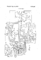
- the capacitive rotor-position sensor 11 of the preferred embodiment shown in FIGS. l-4 determines the instantaneous position of a commutatorless motor rotor I3 and provides a threephase square wave output A, A, B, B, C and C shown in FIG. 5a at a frequency proportional to motor speed and which is indicative of rotor position and thus of the position of the rotor field with respect to the motor stator windings (not shown).
- the three-phase position sensor output establishes the correct stator field sequence with respect to the rotor R so that the power transistors or SCRs which energize the stator windings conduct at the right time and in the proper sequence to maintain the desired direction and rotational velocity of the stator rotating field.
- Capacitive rotor position sensor 11 is particularly adapted for use in a motor control system disclosed in the copending US. patent application of Frederick A. Stich'and Allois F. Geiersbach, S.N. 266,286 entitled Control ForCommutatorless Motor filed June 26, 1972, and to. control the power transistors which energize the stator windings of a commutatorless DC. motor disclosed in the copending US. Patent application of FrederickA. Stich and Glenn W. Schwantes, S.N. 278,577 entitled Commutatorless Motor filed August 7, 1972 both of which have the same assignee as this invention. v
- the motor rotor has p pole pairs, where p is an integer, and the capacitor rotor position sensor has at least pv times a arcuately displaced stationary capacitor plates, where n is an integer equal to the number of motor phases.
- Motor rotor R of the preferred embodiment'shown inFIGS. 14 has 2p pole pairs, i.e., four poles, and capacitive rotor position sensor 11 of the preferred embodiment may have 2pn equals 12 circumferentially displaced metallic capacitor plates, or electrodes- 31 in a common plane perpendicular to the motor rotor axis and defining an annular disk.
- the stationary electrodes 31 may be copper plates in the shape of a sector of a ring subtending an arc of 360/2n equals 60 electrical degrees and affixed to a stationary-annular stator board 40 (See FIGS. 2 and3) mounted by fastening means 4l'to the end, bell 42 of the brushless motor frame S.
- Stationary stator board 40 may be of an insulating material such as fibre glass impregnated with epoxy resin.
- the capacitive rotor position sensor of the invention has a'radially extending rotatable capacitor plate for each pole pair with the radially extending arms displaced 360 electrical degrees.
- a diametrically elongated, rotatable capacitor plate 35 operatively connected to the motor rotor R for rotation therewith and mounted for rotation adjacent stationary capacitor plates 31 comprises two electrically commoned, elongated and narrow radially extending electrodes 36 aligned along adiameter.
- the two electrodes 36 which constitute rotatable capacitor plate 35 are schematically shown in FIG.
- Stationary electrode 39 of coupling capacitor C1 may be a thin annular copper ring 39 (See FIGS. 2 and 3) affixed to stationary stator board 40 radially inward from the stationary capacitor plates 31.
- Movable electrode 38 of coupling capacitor C1 may be a thin annular copper member affixed to a rotating annular rotor board 43 which is fastened to the motor rotor R and preferably is of an insulating material such as fiber glass impregnated with epoxy resin.
- Movable electrode 38 of coupling capacitor C1 so affixed to rotatable rotor board 43 may be spaced by an air gap from stationary electrode 39 fastened to stationary rotor board 40.
- Movable electrode 38 of coupling capacitor C1 may have thin, diametrically opposed fingers 36 integral therewith extending radially outward which constitute the two radially elongated electrodes 36 that define rotatable capacitive plate 35.
- Radial conductors 33 electrically connected to ground are disposed between adjacent stationary capacitor plates 31, and a grounding conductor ring 35 may be disposed between the outer periphery of the stationary electrode 39 of coupling capacitor C1 and the inner margin of the stationary electrodes 31 for the purpose of electrically isolating the stationary plates 31 from each other so that discrimination between the plates is high.
- RELAXATION OSCILLATOR Relaxation oscillator 10 may include a capacitor C2 charged from the battery BAT through a resistance R31 and coupled through a diode D11 to the emitter of a transistor Q21.
- the potential on the base of transistor Q21 is established by a-voltage divider comprising three resistors R32, R33, and R34 connected in series across the battery terminals.
- oscillator 10 has a frequency which is high relative to the electrical frequency that is synchronous to the motor, for example, 20 KHZ for a 5,000 RPM, 4-pole motor.
- the high frequency pulses generated by relaxation oscillator 10 are coupled through rotatable capacitor electrode 35 to the stationary capacitor plates 31 and the load connected thereto.
- Oscillator 10 thus derives read-out" pulses with high frequency components which are distributed by rotatable capacitor plate 35 to a square wave generator 12 through the fixed capacitor plates 31'arranged in the sequence shown in FIG. 1.
- the high frequency components of the read-out'pulses readily couple through adjacent rotatable and fixed capacitor plates 35 and 31.
- the rotatable electrodes 36 (which define rotatable-capacitor plate 35) and the fixed plates 31 are preferably elongated in a radial direction to obtain adequate capacitance, but the width of the rotatable electrodes 36 is held to a minimum to obtain high accuracy.
- the individual stationary plates 31 subtend an arc of approximately 360/2n equals 60 electrical degrees
- the three adjacent stationary capacitor plates 31a, 31b, 31c for phase A coupled to load resistor LRA together subtend 180 electrical degrees (so that the phase A output pulse is of 180 electrical degrees duration) and are also displaced 360/n equals 120 electrical degrees (60 mechanical) from" the three corresponding adjacent stationary plates 31c, 31d, and 31e associated with phase B and also 120 electrical degrees from the three corresponding adjacent stationary capacitor plates 31e, 31f, and 31a associated with phaseC.
- the output fromrelaxation oscillator is connected through. diodeDlZ across a 220K resistor R38-to assure that dischargeof thestationary capacitor plates 31 is not rapid enough to reset the flip-flops which areemployed in some embodiments to convert the logic zero voltage and logic one voltage output signalsfrom the stationary capacitor plates 31 1 into the three phase square waves shown inFIG. 5a.
- SQUARE WAVE GENERATOR Square wave generator 12- may include three similar differential amplif ers 61A, 61B and 61C each of which is associated with one of the motor phases A, B and C I and produces the output forthat phase.
- the difierential amplifiers 61A, 61B, and 61C enhance the one-tozero: ratio ofthe inputs thereto from the stationary plates developed-across the load resistor LR, and one input to eachdifferential amplifier is a logic one signal from a stationary plate 31 having relativelyhigh couplirig at a given instant to rotatable plate35iand the other inputthereto is a logic zero signal from a stationary plate having relatively'low coupling at that instant to rotatable capacitor plate 35.
- the two inputs of each differential amplifier fora given phase are coupled to stationary plates 31 for that phase displaced 180 (electrical); apart so that the twoinputs are receiving logic one and logic zero signals from stationary plates 31.
- differential amplifier 61A having relatively high and relatively low coupling respectively with-rotatable capacitor plate 35.
- a and K'inputs to differential amplifier 61A are respectively coupled throughresistors RA] and RAZ to stationary plates 31a and 31d (or plates 31b and 31d,-
- plates 31c and 31f designated A whenboth electrodes 36 are opposite stationary plates 31a and rotatable electrode 35 is displaced ;90 mechanical degrees (180 electrical).from stationary plate 31d so that minimum coupling exists 'between'plates 31d and 35.
- the inputs to the differential amplifier 61A, 61B and 61C for each phase are coupled'to stationary plates 31 displaced (electrical) from the stationary plates 31 to which the differential amplifiers for the other two phases are coupled so that the outputsA, B and C are displaced 120- electrical.
- the inputs to the phase differential amplifiers 61 are coupled to stationary capacitor plates displaced 360/n electrical degrees, where n is an integer equal to the number of motor phases.
- the A input to differential amplifier 61A for phase A is coupled through RAl resistors to stationary plates 31a, 31b, and 310
- the B input to differential amplifier 61B for phase B is coupled through RBI resistors to stationary plates 31c, 31d and 31e designated 8 which are displaced respectively 120 (electrical) from stationary plates 31a, 31b and 310 designated A.
- the phase B plates 31c, 31d and 31a are displaced 120 (electrical) respectively from the phase C stationaryplates 31e, 31f and 31a designated C.
- the motor rotor R has four poles, and consequently, each pair of diametrically opposed plates 31 which are displaced 360 electrical degrees apart and contain the same information) are electricallyconnec-ted together and thus increase the capacitive coupling between rotatable and stationary plates.
- the pair of diametrically opposed stationary electrodes 31a are connected together, and the pair of diametrically opposed stationary electrodes 31b'are electrically connected together;
- Each pair of electrically commoned stationary plates 31 ' is connected toone of the six in-' puts to each of the three differential amplifiers 61A, 61B and 61C.
- diametrically opposed and electrically are diametrically opposed and electrically.
- commoned stationary plates 31a designated A, B, C are connected through a resistor RAl to an A input .of differential amplifier 61A,through a resistor RB2 to a B input of differential amplifier 61B, and through a resistor RC1 to a C input of differential amplifier 61C.
- resistors RA1 are connected to the pairs of stationary electrodes 31a, 31b and 310 each of which is designated A and subtends 60 electrical degrees and which results in the generation of the A pulse during ary electrode 31a, 31b, and 31c designated A, and since each stationary electrode 31c, 31d and 31e subtends 60 (electrical), pulse B has a period of 3 X 60 180 (electrical) and is displaced 120 (electrical) from the A output pulse.
- flip-tlops convert the one and zero outputs from the stationary plates 31 to the set of three-phase square waves A, A, B, B, C and C shown in FIG. 5a, and preferably such flip-flops use a common .emitter resistor so that each flip-flop performs as a positively fed-back difference amplifier during the switching transition to assure that there is positive discrimination between the one and zero inputs.
- Square wave generator 12- also preferably includes three NAND gate latch circuits LCA, LCB and LCC each of which is associated with one of the phases and the differential amplifier for that phase.
- differential amplifier 61A and latch circuit LCA are associated with phase A and together generate the square wave pulse A for phase A and its negation A (which is the inverse of A).
- differential amplifier 61A is of conventional configuration, and the base of one transistor Q23 is coupled to load resistor LRA which is common to the three resistors RAl which add the signals from thepairs of position sensor stationary plates 31a, 31b, and 310 respectively that are designated A and together subtend 180 electrical degrees.
- the base of the other transistor Q24 of differential amplifier 61A is coupled to load resistor m which is common to the three A input-resistors RA2 which are individually connected to the pairs of stationary plates 31d, 31c, and 31f designat'ed'A and sum the signals therefrom.
- the active elements of the differential amplifiers 61A, 61B, and 61C are preferably integrated circuits, and differential amplifier 61B is symbolically shown as being one half of an integrated circuit which is commercially available from RCA Corporation under thetype designation CA3026.
- Differential amplifier 61A provides a low voltage, or logic 0 output on the collector ofthat transistor Q23 or Q24 having itsb'ase coupled to the three pairs of stationaryplates 31a, 315,310 or 31d, 31e, 31], having the greatest coupling to the rotatable electrode 35, thereby giving an indication of the position .of the motor rotor RQFor example, if rotatable electrodes 36 are in a position where thesum of the readout pulses received on the pairs of'plates 31a, 31b, and 31c designated A is greater than the sum of.
- Differential amplifiers 61A,'61B, and 61C enhance the "one-to-zero ratio, of the input from stationary plates 31 and control NAND gate latch circuits LCA,
- the collector of transistor Q23 is coupled to one input of a NAND gate NAND 1
- the collector of transistor Q24 is coupled to one input of a NAND gate NAND2.
- the output from gate NANDl is coupled to the other input of gate NAND2 and provides positive feedback to the base of transistor 023 through a resistor R39.
- the output from gate NAND2 is coupled to the other input of gate NANDl and provides positive feedback through a resistor R40 to the base of transistor Q24.
- gate NAND2 thus provides a logic 0 voltage on A output conductor which is also coupled to the said other input of gate NANDl, thereby latching gate NANDl with logic 1 on its output and on the A output conductor.
- Synchronous pulse generator 14 receives the threephase square waves A, B, and C and their complements A, B, and C from square wave generator 12 and generates anegative-going pulse P shown in FIG. 5b at every square wave edge of the outputfrom square wave generator 12. Synchronous pulse generator 14 thus derives a train of pulses wherein each pulse P corresponds to a change of state of the latch circuits LCA, LCB and LCC. Inasmuch as there are six edges per cycle of the three-phase square waves A, A, B, B, C and C, six pulses are derived by synchronous pulse generator 14 at a frequency proportional to motor speed for each cycle of the three-phase square wave output from square wave generator 12.
- Synchronous pulse generator 14 includes a singleended differential amplifier of conventional design wherein the base of one transistor Q25 is coupled to the A, Band C leads from the latch circuits LCA, LCB, and LCC of the square wave generator 12 through individual differentiating capacitors C3.
- the base of the other transistor Q26 of differential amplifier 70 is coupled to the A, B, and C leads from square wave generator 12 through individual differentiating capacitors C4.
- the collectors of transistors Q25 and 026 are commoned and connected to the output lead in which the train of synchronizing pulses P shown in FIG. 5b appears.
- Each transistor Q25 and Q26 is preferably one half of an integrated circuit element similar to that sold by RCA Corporation under the type designation CA3026.
- the input capacitors C3 and C4 differentiate the square wave outputs A, B, C, A, hand 6 from square wave generator 12, and the differential amplifier 70 is operated in an overdriven mode and shapes the pulses to form a single train of negative going pulses P at the commoned collectors, as shown in FIG.
- phase signal complement electrical degrees from the first plates coupled to the other inputof the differential amplifier to derive the phase signal complement
- second stationary plates 31d, 31c, and 31f displaced 1'80 electrical degrees fromcorresponding first plates 31a, 31b and 310 are coupled to the A input of differential amplifier-61A to derive signal A
- n'stationary capacitor plates-are provided to derive the phase'output signal e.g.', A, and other.
- means areutilized to generate its complement, i.e., X, when the phase output signal, such as A, is absent.
- v v 1 It should-be understood that I do not intend to be limited to the particular embodiment shown and described for many modifications and variations thereof will be readilyapparent to those skilled in the art.
- a capacitiveposition sensor for indicating the position of a rotatable member comprising, in combination, p
- v aplurality of stationary capacitor plates circumferentially displaced from each other in a plane adjacent to said rotatable plateand perpendicular to the axis thereof and each of which subtendsa substantially greater arc aboutsaid axis of rotation than said rotatable plate, an oscillator adapted to generate high frequency pulses, 1 means for couplingthe output of said oscillator to said rotatable-plate, and
- indicating means coupled to said stationary capacitor plates and responsive to the high frequency pulses from said oscillator passing. through the capacitance between said rotatable plate and each said stationary plate as said rotatable plate revolves for generating an output pulse when said rotatable plate is opposite each stationary plate indicative of the instantaneous position of said rotatable member.
- said indicating means includes n differential amplifiers each of which has one of its inputs electrically coupled to a plurality of adjacent first stationary capacitor plates which together subtend 180 electrical degrees and its other input coupled to a plurality of adjacent second stationary capacitor plates which are displaced 180 electrical degrees from said first stationary plates, and wherein saidfirst stationary capacitor plates coupled to said one input of each differential amplifier are displaced 360/n electrical degrees from the first sta one input of each of the other differential amplifiers: f
- a capacitive'position sensor in accordance with claim I wherein said rotatable member is the rotor of an electric motor having n phases and p rotor pole pairs, where n and p are integers, and wherein said rotor position sensor includes at least n times p of said stationary capacitor plates and derives an n-phase train of output pulses indicative of the instantaneous position of said rotor having a frequency which is a function of the angular velocity of said rotor.
- a capacitive rotor position sensor in accordance with claim 7 including n times 2p stationary capacitor plates and said indicating means includes n differential amplifiers each of which derives the-output pulses forone of said phases and has its inputs coupled to stationary capacitor plates displaced 180 electrical degrees apart.
- a capacitive rotor position sensor in accordance with claim 8 wherein a plurality of first stationary capacitor plates which together subtend 180 electrical degrees are electrically coupled to one input of each of said differential amplifiers and are displaced 360/n electrical degrees from the first stationary capacitor plates which are coupled to said one input of each of the other differential amplifiers, whereby each said differential amplifier derives output pulses of 180 electrical degrees duration for one phase displaced 360/n electrical degrees from the other phase output pulses.
- a capacitive rotor position sensor in accordance with claim 9 wherein a plurality of second stationary capacitor plates which together subtend 180 electrical degrees are electrically coupled to the other input of each of said differential amplifiers and are displaced 180 electrical degrees from said first stationary plates which are coupled to said one input, and wherein each of said first and said second stationary plates subtend 360/2n electrical degrees, whereby a phase output pulse of 180 electrical degrees duration is generated when said rotatable plate is opposite said first stationary plates and its complement is generated when said rotatable plate is opposite said second stationary plates.
- a capacitive rotor position sensor in accordance with claim 7 including n times 2p stationary capacitor plates and said indicating means includes 11 pulse amplifier means each of which is associated with one phase of said motor and is electrically coupled to a plurality of first stationary capacitor plates each of which subtends 360/2n electrical degrees and which together subtend 180 electrical degrees and which are displaced 360/n electrical degrees from the first stationary plates coupled to each of the other pulse amplifying means.
- a capacitive rotor position sensor for generating an n-phase train of pulses indicative of the position of the rotor of an electric motor having 11 phases and p pairs of rotor poles and at a frequency proportional to the angular velocity of said rotor, where n and p are integers, comprising, in combination,
- a rotatable, radially elongated capacitor plate operatively connected to said rotor for rotation therewith
- a high frequency oscillator adapted to generate steep wavefront pulses electrically coupled to said rotatable plate
- n indicating means each associated with one phase of said motor and including a load impedance coupled to a plurality of adjacent first stationary capacitor plates for generating an output pulse in response to the high frequency pulses from said oscillator coupled through the capacitance between said rotatable and stationary plates when said rotatable plate is opposite each of said stationary plates as it revolves, the plurality of adjacent first stationary plates of each said indicating means coupled to said load impedance of one phase together subtending electrical degrees and being displaced 360/n electrical degrees from the first stationary plates coupled to the load impedances associated with the other phases.
- each said indicating means includes a differential amplifier having one input coupled to said load impedance and to said first stationary plates of the associated phase and having its other input coupled to a plurality of adjacent second stationary plates which together subtend 180 electrical degrees and are displaced 180 electrical degrees from said first plates.
- each said indicating means also includes bistable circuit means coupled to the output of the associated differential amplifier for generating square wave pulses indicative of the position of said rotor, said bistable circuit means providing positive feedback to the inputs to the associated differential amplifier to enhance discrimination between stationary capacitor plates.
- a capacitive rotor position sensor for generating a three-phase train of pulses indicative of the position of the rotor of an electric motor having three pairs of rotor poles comprising, in combination,
- a rotatable, diametrically elongated capacitor plate operatively connected to said rotor for rotation therewith
- a high frequency oscillator coupled to said rotatable plate
- a coupling capacitor having a stationary electrode disposed in said plane radially inward from said sta' tionary capacitor plates and a rotatable electrode spaced in an axial direction by an air gap from said stationary electrode and having a pair of diametrically opposed, radially extending, narrow portions integral therewith positioned opposite said stationary capacitor plates and together constituting said rotatable capacitor plate, said oscillator being coupled to said rotatable capacitor plate by said coupling capacitor.
- a capacitive rotor position sensor in accordance with claim 24 and including grounded conductor means extending radially between adjacent stationary plates and also between the inner periphery of said stationary plates and said coupling'capacitor stationary electrode for electrically isolating said stationary capacitor plates from each other.
Landscapes
- Engineering & Computer Science (AREA)
- Power Engineering (AREA)
- Transmission And Conversion Of Sensor Element Output (AREA)
Applications Claiming Priority (1)
| Application Number | Priority Date | Filing Date | Title |
|---|---|---|---|
| US25341872A | 1972-05-15 | 1972-05-15 |
Publications (1)
| Publication Number | Publication Date |
|---|---|
| US3760392A true US3760392A (en) | 1973-09-18 |
Family
ID=22960183
Family Applications (1)
| Application Number | Title | Priority Date | Filing Date |
|---|---|---|---|
| US00253418A Expired - Lifetime US3760392A (en) | 1972-05-15 | 1972-05-15 | Capacitive position sensor |
Country Status (8)
| Country | Link |
|---|---|
| US (1) | US3760392A (Direct) |
| JP (1) | JPS5549683B2 (Direct) |
| AU (1) | AU5551573A (Direct) |
| CA (1) | CA984483A (Direct) |
| DE (1) | DE2324472A1 (Direct) |
| FR (1) | FR2184825B1 (Direct) |
| GB (1) | GB1419885A (Direct) |
| IT (1) | IT985028B (Direct) |
Cited By (39)
| Publication number | Priority date | Publication date | Assignee | Title |
|---|---|---|---|---|
| US3900780A (en) * | 1972-02-03 | 1975-08-19 | Canon Kk | Control circuit for electric motors |
| US4199800A (en) * | 1978-05-01 | 1980-04-22 | Contraves Goerz Corporation | Brushless DC tachometer |
| US4233593A (en) * | 1978-06-12 | 1980-11-11 | General Electric Company | Capacitive touch control and display |
| US4264903A (en) * | 1978-06-12 | 1981-04-28 | General Electric Company | Capacitive touch control and display |
| US4292632A (en) * | 1978-08-29 | 1981-09-29 | Yeakley Lester M | Displacement sensing device having capacitance transduction element |
| US4350981A (en) * | 1979-07-02 | 1982-09-21 | Nippon Soken, Inc. | Capacitive rotational position detector |
| US4418348A (en) * | 1978-12-27 | 1983-11-29 | Nippon Soken, Inc. | Rotation position detector using stationary and rotatable disk plates |
| US4471450A (en) * | 1982-02-01 | 1984-09-11 | Schlumberger Canada Limited | Register position sensing and controlling apparatus |
| US4477810A (en) * | 1981-09-07 | 1984-10-16 | Nippon Soken, Inc. | Capacity type rotation detecting apparatus |
| US4488152A (en) * | 1982-02-01 | 1984-12-11 | Schlumberger Canada Limited | Register position sensing and controlling apparatus |
| US4499465A (en) * | 1981-03-18 | 1985-02-12 | Nippon Soken, Inc. | Capacitive-type incremental and reference angular rotation detecting apparatus |
| US4523195A (en) * | 1981-03-09 | 1985-06-11 | Nippon Soken, Inc. | Rotational direction and angle detecting apparatus |
| US4571529A (en) * | 1982-12-02 | 1986-02-18 | Willi Studer, Ag | Actual speed value converter for the speed control in a motor drive system |
| US4638249A (en) * | 1981-01-22 | 1987-01-20 | Nippon Soken, Inc. | Incremental encoder rotational position detector |
| US4737699A (en) * | 1985-04-01 | 1988-04-12 | Xian Instrumentation Factory | Capacitive position transducer |
| US4814676A (en) * | 1981-08-17 | 1989-03-21 | U.S. Philips Corporation | Self-starting brushless D.C. motor |
| US4827196A (en) * | 1987-12-03 | 1989-05-02 | E. I. Du Pont De Nemours And Company | Motor control arrangement |
| US4958115A (en) * | 1988-11-28 | 1990-09-18 | At&T Bell Laboratories | Capacitively commutated brushless DC servomotors |
| US5077635A (en) * | 1990-05-22 | 1991-12-31 | Robert Bosch Gmbh | Capacitive position sensor |
| US5432421A (en) * | 1991-10-26 | 1995-07-11 | Brose Fahrzeugteile Gmbh & Co. Kg | Process for detecting the position, direction of movement and dynamic characteristic values of remote-controlled displacement of an adjustable object |
| US5648642A (en) * | 1992-06-08 | 1997-07-15 | Synaptics, Incorporated | Object position detector |
| US5854625A (en) * | 1996-11-06 | 1998-12-29 | Synaptics, Incorporated | Force sensing touchpad |
| US5861583A (en) * | 1992-06-08 | 1999-01-19 | Synaptics, Incorporated | Object position detector |
| US5872408A (en) * | 1997-02-12 | 1999-02-16 | Rakov; Mikhail A. | Capacitive sensor for indicating position |
| US5880411A (en) * | 1992-06-08 | 1999-03-09 | Synaptics, Incorporated | Object position detector with edge motion feature and gesture recognition |
| US5889236A (en) * | 1992-06-08 | 1999-03-30 | Synaptics Incorporated | Pressure sensitive scrollbar feature |
| US6028271A (en) * | 1992-06-08 | 2000-02-22 | Synaptics, Inc. | Object position detector with edge motion feature and gesture recognition |
| US6239389B1 (en) | 1992-06-08 | 2001-05-29 | Synaptics, Inc. | Object position detection system and method |
| US6380929B1 (en) | 1996-09-20 | 2002-04-30 | Synaptics, Incorporated | Pen drawing computer input device |
| US6731107B2 (en) * | 2000-05-12 | 2004-05-04 | Alcatel | Star-connected sensor |
| US20060145689A1 (en) * | 2005-01-04 | 2006-07-06 | Taylor G B | Electromagnetic sensor systems and methods of use thereof |
| WO2005086767A3 (en) * | 2004-03-08 | 2006-07-13 | G Brandt Taylor | Induction sensor |
| US20070279138A1 (en) * | 2004-03-08 | 2007-12-06 | Taylor Engineering, Inc. | Induction Sensor |
| US20080036546A1 (en) * | 2005-03-07 | 2008-02-14 | Taylor G B | Electromagnetic sensor systems |
| US20080116882A1 (en) * | 2005-03-07 | 2008-05-22 | Digisensors, Inc. | Electromagnetic sensor systems |
| US20090091336A1 (en) * | 2007-10-04 | 2009-04-09 | Steven Basil Al-Rawi | Capacitive Position Sensor |
| CN100523713C (zh) * | 2004-03-08 | 2009-08-05 | G·勃兰特·泰勒 | 感应传感器 |
| US20100283416A1 (en) * | 2008-03-04 | 2010-11-11 | Yoshitaka Onishi | Brushless motor device and control device |
| US20110025066A1 (en) * | 2008-01-21 | 2011-02-03 | Avio S.P.A. | Electromagnetic device with reversible generator-motor operation |
Families Citing this family (4)
| Publication number | Priority date | Publication date | Assignee | Title |
|---|---|---|---|---|
| DK143423C (da) | 1979-03-22 | 1981-12-21 | Brueel & Kjaer As | Strimmelskriver med en differentialkondensator som positionsgiver til en positionsservo for skrivepennen |
| DE3637529A1 (de) * | 1986-09-02 | 1988-03-17 | Hengstler Gmbh | Kapazitiver linear- oder drehgeber zum steuern und positionieren von bewegten gegenstaenden |
| GB201409182D0 (en) * | 2014-05-23 | 2014-07-09 | Pragmatic Printing Ltd | Capacitive detection system |
| JP2020178448A (ja) * | 2019-04-18 | 2020-10-29 | 日本電産株式会社 | モータ |
-
1972
- 1972-05-15 US US00253418A patent/US3760392A/en not_active Expired - Lifetime
-
1973
- 1973-01-03 CA CA160,435A patent/CA984483A/en not_active Expired
- 1973-05-10 AU AU55515/73A patent/AU5551573A/en not_active Expired
- 1973-05-11 GB GB2261373A patent/GB1419885A/en not_active Expired
- 1973-05-14 IT IT49928/73A patent/IT985028B/it active
- 1973-05-14 FR FR7317416A patent/FR2184825B1/fr not_active Expired
- 1973-05-15 JP JP5403673A patent/JPS5549683B2/ja not_active Expired
- 1973-05-15 DE DE2324472A patent/DE2324472A1/de not_active Ceased
Cited By (52)
| Publication number | Priority date | Publication date | Assignee | Title |
|---|---|---|---|---|
| US3900780A (en) * | 1972-02-03 | 1975-08-19 | Canon Kk | Control circuit for electric motors |
| US4199800A (en) * | 1978-05-01 | 1980-04-22 | Contraves Goerz Corporation | Brushless DC tachometer |
| US4233593A (en) * | 1978-06-12 | 1980-11-11 | General Electric Company | Capacitive touch control and display |
| US4264903A (en) * | 1978-06-12 | 1981-04-28 | General Electric Company | Capacitive touch control and display |
| US4292632A (en) * | 1978-08-29 | 1981-09-29 | Yeakley Lester M | Displacement sensing device having capacitance transduction element |
| US4418348A (en) * | 1978-12-27 | 1983-11-29 | Nippon Soken, Inc. | Rotation position detector using stationary and rotatable disk plates |
| US4350981A (en) * | 1979-07-02 | 1982-09-21 | Nippon Soken, Inc. | Capacitive rotational position detector |
| US4638249A (en) * | 1981-01-22 | 1987-01-20 | Nippon Soken, Inc. | Incremental encoder rotational position detector |
| US4523195A (en) * | 1981-03-09 | 1985-06-11 | Nippon Soken, Inc. | Rotational direction and angle detecting apparatus |
| US4499465A (en) * | 1981-03-18 | 1985-02-12 | Nippon Soken, Inc. | Capacitive-type incremental and reference angular rotation detecting apparatus |
| US4814676A (en) * | 1981-08-17 | 1989-03-21 | U.S. Philips Corporation | Self-starting brushless D.C. motor |
| US4477810A (en) * | 1981-09-07 | 1984-10-16 | Nippon Soken, Inc. | Capacity type rotation detecting apparatus |
| US4488152A (en) * | 1982-02-01 | 1984-12-11 | Schlumberger Canada Limited | Register position sensing and controlling apparatus |
| US4471450A (en) * | 1982-02-01 | 1984-09-11 | Schlumberger Canada Limited | Register position sensing and controlling apparatus |
| US4571529A (en) * | 1982-12-02 | 1986-02-18 | Willi Studer, Ag | Actual speed value converter for the speed control in a motor drive system |
| US4737699A (en) * | 1985-04-01 | 1988-04-12 | Xian Instrumentation Factory | Capacitive position transducer |
| US4827196A (en) * | 1987-12-03 | 1989-05-02 | E. I. Du Pont De Nemours And Company | Motor control arrangement |
| US4958115A (en) * | 1988-11-28 | 1990-09-18 | At&T Bell Laboratories | Capacitively commutated brushless DC servomotors |
| US5077635A (en) * | 1990-05-22 | 1991-12-31 | Robert Bosch Gmbh | Capacitive position sensor |
| US5432421A (en) * | 1991-10-26 | 1995-07-11 | Brose Fahrzeugteile Gmbh & Co. Kg | Process for detecting the position, direction of movement and dynamic characteristic values of remote-controlled displacement of an adjustable object |
| US5889236A (en) * | 1992-06-08 | 1999-03-30 | Synaptics Incorporated | Pressure sensitive scrollbar feature |
| US20040178997A1 (en) * | 1992-06-08 | 2004-09-16 | Synaptics, Inc., A California Corporation | Object position detector with edge motion feature and gesture recognition |
| US7109978B2 (en) | 1992-06-08 | 2006-09-19 | Synaptics, Inc. | Object position detector with edge motion feature and gesture recognition |
| US5861583A (en) * | 1992-06-08 | 1999-01-19 | Synaptics, Incorporated | Object position detector |
| US5841078A (en) * | 1992-06-08 | 1998-11-24 | Synaptics, Inc. | Object position detector |
| US5880411A (en) * | 1992-06-08 | 1999-03-09 | Synaptics, Incorporated | Object position detector with edge motion feature and gesture recognition |
| US5648642A (en) * | 1992-06-08 | 1997-07-15 | Synaptics, Incorporated | Object position detector |
| US6028271A (en) * | 1992-06-08 | 2000-02-22 | Synaptics, Inc. | Object position detector with edge motion feature and gesture recognition |
| US6239389B1 (en) | 1992-06-08 | 2001-05-29 | Synaptics, Inc. | Object position detection system and method |
| US6380931B1 (en) | 1992-06-08 | 2002-04-30 | Synaptics Incorporated | Object position detector with edge motion feature and gesture recognition |
| US6750852B2 (en) | 1992-06-08 | 2004-06-15 | Synaptics, Inc. | Object position detector with edge motion feature and gesture recognition |
| US6414671B1 (en) | 1992-06-08 | 2002-07-02 | Synaptics Incorporated | Object position detector with edge motion feature and gesture recognition |
| US6610936B2 (en) | 1992-06-08 | 2003-08-26 | Synaptics, Inc. | Object position detector with edge motion feature and gesture recognition |
| US6380929B1 (en) | 1996-09-20 | 2002-04-30 | Synaptics, Incorporated | Pen drawing computer input device |
| US5854625A (en) * | 1996-11-06 | 1998-12-29 | Synaptics, Incorporated | Force sensing touchpad |
| US5872408A (en) * | 1997-02-12 | 1999-02-16 | Rakov; Mikhail A. | Capacitive sensor for indicating position |
| US6731107B2 (en) * | 2000-05-12 | 2004-05-04 | Alcatel | Star-connected sensor |
| CN100523713C (zh) * | 2004-03-08 | 2009-08-05 | G·勃兰特·泰勒 | 感应传感器 |
| US7528597B2 (en) | 2004-03-08 | 2009-05-05 | Digisensors, Inc. | Induction sensor |
| US20070279138A1 (en) * | 2004-03-08 | 2007-12-06 | Taylor Engineering, Inc. | Induction Sensor |
| WO2005086767A3 (en) * | 2004-03-08 | 2006-07-13 | G Brandt Taylor | Induction sensor |
| US20060145689A1 (en) * | 2005-01-04 | 2006-07-06 | Taylor G B | Electromagnetic sensor systems and methods of use thereof |
| US7511476B2 (en) | 2005-01-04 | 2009-03-31 | Digisensors, Inc. | Electromagnetic sensor systems and methods of use thereof |
| US20080116882A1 (en) * | 2005-03-07 | 2008-05-22 | Digisensors, Inc. | Electromagnetic sensor systems |
| US20080036546A1 (en) * | 2005-03-07 | 2008-02-14 | Taylor G B | Electromagnetic sensor systems |
| US7816911B2 (en) | 2005-03-07 | 2010-10-19 | Digisensors, Inc. | Electromagnetic sensor systems |
| US7898244B2 (en) | 2005-03-07 | 2011-03-01 | Digisensors, Inc. | Electromagnetic sensor systems |
| US20090091336A1 (en) * | 2007-10-04 | 2009-04-09 | Steven Basil Al-Rawi | Capacitive Position Sensor |
| US20110025066A1 (en) * | 2008-01-21 | 2011-02-03 | Avio S.P.A. | Electromagnetic device with reversible generator-motor operation |
| US8536751B2 (en) * | 2008-01-21 | 2013-09-17 | Avio S.P.A. | Electromagnetic device with reversible generator-motor operation |
| US20100283416A1 (en) * | 2008-03-04 | 2010-11-11 | Yoshitaka Onishi | Brushless motor device and control device |
| US8395337B2 (en) * | 2008-03-04 | 2013-03-12 | Mitsubishi Electric Corporation | Brushless motor device and control device |
Also Published As
| Publication number | Publication date |
|---|---|
| JPS5549683B2 (Direct) | 1980-12-13 |
| JPS4956659A (Direct) | 1974-06-01 |
| DE2324472A1 (de) | 1973-11-29 |
| IT985028B (it) | 1974-11-30 |
| CA984483A (en) | 1976-02-24 |
| AU5551573A (en) | 1974-11-14 |
| FR2184825A1 (Direct) | 1973-12-28 |
| FR2184825B1 (Direct) | 1977-11-04 |
| GB1419885A (en) | 1975-12-31 |
Similar Documents
| Publication | Publication Date | Title |
|---|---|---|
| US3760392A (en) | Capacitive position sensor | |
| US3238399A (en) | Self-starting low power synchronous step motor | |
| US4262237A (en) | Commutatorless direct current motor drive system | |
| US4262236A (en) | Commutatorless direct current motor drive system | |
| US3784888A (en) | Control for commutatorless motor | |
| US3532916A (en) | Synchronous rotating machines having non-magnetic tubular armatures | |
| US3109114A (en) | Multiple-winding electrical rotating machines | |
| EP0059763B1 (en) | D.c. generator type non-contact speed sensing device | |
| US4692675A (en) | Control and energization circuit for a brushless d-c motor | |
| US5334921A (en) | Circuit arrangement for operating a multi-phase synchronous motor in a direct voltage network | |
| GB962322A (en) | Improvements in dynamo electric machines of the flat annular air-gap type | |
| US3419782A (en) | Direct current commutation system for brushless electrical motors | |
| US3231774A (en) | A.c. rotating electric machines with printed circuit armatures | |
| GB1202575A (en) | Improvements in or relating to electric tachogenerators | |
| US2644903A (en) | Self-starting electrostatic generator | |
| US3660739A (en) | Means to promote the commutation of a thyristor switching arrangement for an electric motor at low motor speeds | |
| US4035699A (en) | Brushless direct current machine and method of controlling the same | |
| US3631529A (en) | Apparatus for eliminating spark noise generated from a direct current motor | |
| GB1059793A (en) | Improvements in d.c. dynamo-electric machines | |
| JPS57208853A (en) | Direct current brushless motor | |
| US3453515A (en) | Variable frequency polyphase current generator for controlling the speed of an electric motor | |
| GB1266312A (Direct) | ||
| RU2705420C1 (ru) | Генератор многофазной системы ЭДС с механической коммутацией | |
| US3449654A (en) | Direct current commutation system for brushless electrical motors | |
| KR900011105A (ko) | 단극 및 단극다극화 발전방식 |
Legal Events
| Date | Code | Title | Description |
|---|---|---|---|
| AS | Assignment |
Owner name: WOODS KATHLEEN D., AS TRUSTEE Free format text: SECURITY INTEREST;ASSIGNOR:ALLIS-CHALMERS CORPORATION A DE CORP.;REEL/FRAME:004149/0001 Effective date: 19830329 Owner name: CONNECTICUT NATIONAL BANK THE, A NATIONAL BANKING Free format text: SECURITY INTEREST;ASSIGNOR:ALLIS-CHALMERS CORPORATION A DE CORP.;REEL/FRAME:004149/0001 Effective date: 19830329 |