US3718020A - Rolling mill - Google Patents
Rolling mill Download PDFInfo
- Publication number
- US3718020A US3718020A US00119617A US3718020DA US3718020A US 3718020 A US3718020 A US 3718020A US 00119617 A US00119617 A US 00119617A US 3718020D A US3718020D A US 3718020DA US 3718020 A US3718020 A US 3718020A
- Authority
- US
- United States
- Prior art keywords
- sleeves
- adjusting
- fact
- recited
- roll head
- Prior art date
- Legal status (The legal status is an assumption and is not a legal conclusion. Google has not performed a legal analysis and makes no representation as to the accuracy of the status listed.)
- Expired - Lifetime
Links
Images

Classifications
-
- B—PERFORMING OPERATIONS; TRANSPORTING
- B21—MECHANICAL METAL-WORKING WITHOUT ESSENTIALLY REMOVING MATERIAL; PUNCHING METAL
- B21B—ROLLING OF METAL
- B21B27/00—Rolls, roll alloys or roll fabrication; Lubricating, cooling or heating rolls while in use
- B21B27/02—Shape or construction of rolls
-
- B—PERFORMING OPERATIONS; TRANSPORTING
- B21—MECHANICAL METAL-WORKING WITHOUT ESSENTIALLY REMOVING MATERIAL; PUNCHING METAL
- B21B—ROLLING OF METAL
- B21B13/00—Metal-rolling stands, i.e. an assembly composed of a stand frame, rolls, and accessories
- B21B13/008—Skew rolling stands, e.g. for rolling rounds
-
- B—PERFORMING OPERATIONS; TRANSPORTING
- B21—MECHANICAL METAL-WORKING WITHOUT ESSENTIALLY REMOVING MATERIAL; PUNCHING METAL
- B21B—ROLLING OF METAL
- B21B31/00—Rolling stand structures; Mounting, adjusting, or interchanging rolls, roll mountings, or stand frames
- B21B31/16—Adjusting or positioning rolls
- B21B31/18—Adjusting or positioning rolls by moving rolls axially
-
- B—PERFORMING OPERATIONS; TRANSPORTING
- B21—MECHANICAL METAL-WORKING WITHOUT ESSENTIALLY REMOVING MATERIAL; PUNCHING METAL
- B21B—ROLLING OF METAL
- B21B33/00—Safety devices not otherwise provided for; Breaker blocks; Devices for freeing jammed rolls for handling cobbles; Overload safety devices
Definitions
- Another object of this invention is the provision of a rolling mill having a special design for the tightening of the roller to keep the necessary adjustment range small and reduce it so far that it may be selected only on the basis of the variation range required for the adjustment.
- the invention consists of a rolling mill in which the shafts of bevel rollers are designed as hollow shafts in which sliding sleeves are held and locked against turning with adjusting means determining their axial positions.
- the sliding sleeves are penetrated by tension rods which always lie with a collar engaging a shoulder of the sliding sleeve and serve to tighten the bevel rollers by threaded means against the free end of the sliding sleeves.
- the sliding sleeves are advantageous to equip the sliding sleeves with threads which engage threads inside adjusting sleeves, the latter being secured against axial displacement inside the hollow shafts.
- the adjusting sleeves are connected on one side against turning with the hollow shafts, so that unintentional movement during operation is prevented. It has proven to be of advantage to design the adjusting sleeves in such a way that, after disconnecting the connection against turning, they are turned against the hollow shaft by driving devices. For practical purposes, this is achieved in such a way that the adjusting sleeves can be operated by one or by several driving devices.
- special adjusting devices can be dropped by connecting selective controllable coupling sleeves to the adjusting sleeves which, in one of their positions, connect the adjusting sleeves against turning with the roller head housing and, in the other position, are connected to the hollow shaft.
- a retraction of the bevel rollers for roller exchange may be prevented completely when the carrier at the side of the sliding sleeve is designed in such a way that its bevel of the cone has a tip angle which exceeds double the slope angle of the roller shaft against the rolling stock axis.
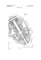
- FIG. 1 is a vertical sectional view of a portion of a rolling mill constructed in accordance with the principles of the present invention.
- FIG. 2 is a vertical sectional view of a portion of a modified form of the rolling mill.
- FIG. 1 shows a conical roll 1 in which the roll head contains three conical rolls arranged at from each other.
- the conical rolls are equipped with a left-hand thread for receiving a carrier part 2.
- the carrier part 2 By selecting the left-hand thread, the carrier part 2, through the momentum of the operation, is screwed tightly into the conical roll 1.
- the carrier part 2 is of a conical-shaped design with a large pointed angle and is positioned with the base of the cone against the support areas of the conical roll 1. At the elevation of these support areas, the cross-section of the carrier part is reduced toward a fracture point 3, and within the front part of the carrier part 2 are arranged keyways 4 for engaging the tools necessary for loosening the carrier part 2 in the conical roll 1.
- the tools may also be used for the removal of the sheared-off remains of carrier part from the roll.
- the roll 1 is initially pressed with its carrier part 2 against a correspondingly conically shaped recess of a sliding sleeve 5 by means of a tension rod 6.
- the rod is supported with its collar 7 resting on a shoulder 8 of the sliding sleeve 5 and is threadedly engaged at the front end with a corresponding female thread formed in the carrier part 2.
- the tension rod 6 can be tightened and loosened with a tool which engages a square head 9 arranged on the opposite end of the rod.
- the carrier part 2 is secured against turning by a key 10 which engages oppositely positioned keyways formed on the carrier part and the sliding sleeve 5.
- the sliding sleeve Sis movable lengthwiseand is secured against turning by a key 11 engaging keyways and is held inside the hollow shaft 12.
- the latter is driven through bevel gears 13 and 14 by a planetary shaft 15.
- the axial position of the sliding sleeve 5 may be adjusted by an adjusting sleeve 16 which has a male thread which engages a female thread in the sliding sleeve 5 and is rotatably supported inside the hollow shaft.
- the adjust sleeve 16 is secured against axial displacement by a collar 17, one flank of which is supported by the front area of a bearing 18 and the other flank of which is supported by the front area of a supporting ring 19.
- such a turning movement of the adjusting sleeve 16 could be made manually with a tool; for practical purposes, the adjusting sleeve 16 is locked against turning after the adjustment by the connecting sleeve 16 with the sliding sleeve 5 or the hollow shaft 12.
- the controlled adjustment is made by a power drive without an additional power drive being necessary.
- the drive is activated through the planetary shaft which, for example, may be activated by the super-imposed motor of the planetary drive of the roller head and can be used forthe axial adjustment of the three bevel rollers of the roller head.
- a coupling sleeve 20 On the rear section of the adjusting sleeve 16 is displaceably arranged a coupling sleeve 20, which is kept from turning by lugs 21 resting in keyways in the adjusting sleeve 16 and is maintained under tension by a spring 22 in the working position shown.
- the coupling sleeve has teeth 23 which engage spaces between oppositely-positioned teeth of the ho]- low shaft 12.
- the teeth 23 of the coupling sleeve 20 move axially away from the oppositely positioned teeth on the hollow shaft 12, so that the locking connection between the hollow shaft and the coupling sleeve is loosened and with it also the adjusting sleeve 16.
- the teeth 28 move into engagement with the gear 29 which is fixed to the shaft housing 36.
- the adjusting sleeve 16 is locked against turning relative to the shaft housing 30 by the coupling sleeve 20. If the super-imposed motor of the planetary drive is now electrically energized, the planetary shaft 15 is driven and, consequently, drives the hollow shaft 12.
- shut-off valves 34 which permit any one ring piston 24 and its coupling sleeve 20 to be excluded from the adjustment. This also makes it possible to make corrections of the axial adjustment of the individual conical rolls of the roll head. In case the rolls are not to be adjusted, but only exchanged (or when the remainder of the carrier part 2 connected with the sliding sleeve 5 is to be removed after a break on the fracture point 3), then a cover 32 of the corresponding shaft housing can be lifted; the square end 9 of tension rod if then rendered accessible so that the carrier part 2 may be screwed out.
- the conical roll 1 and the carrier part 2 are free.
- the flat conical shape of the carrier part 2 permits its removal to the front (in the drawing, towards the right-hand side) without it being necessary to pull back the sliding sleeve 5 first.
- FIG. 2 shows a possible variation of the construction of the rolling mill.
- This figure shows in longitudinal section a shaft with a conical roll associated with a roll head which, in a manner similar to that shown in FIG. 1, has a total of three roll shafts displaced from each other by 120.
- the drive of the shown roller shaft is made by a planetary gear through a planetary shaft and a bevel gear pair, similar to those shown in FIG. 1.
- a conical roll 36 is used which is clamped directly against a supporting area of a sliding sleeve 37 and is secured against turning by interlocking elements on this sliding sleeve and the roll.
- Tightening is brought about by means of a tension rod 38 extending through the sliding sleeve 37; a shoulder formed on the rod is supported on a supporting area of the sleeve and its thread engages a clamping part 39.
- the latter extends through a central bore in the roll 36 and is tightened by means of a ring nut 40.
- a chamber 42 which is made fluid tight by seals 43.
- Pressure fluid may be admitted through a pressure fluid canal 44 and its fitting 45. The pressure fluid entering the chamber presses the support area 41 and the opposite face area of clamping part 39 apart and places the rod 38 in tension and stretches it.
- the tension originated by the ring nut 40 is partially eliminated, the holding thread is relieved, and the ring nut 40 (positioned in a recess of the face area of the roll 36) may be removed easily for changing rolls.
- the conical roll may be tightened.
- the roll will be brought first into its ideal position. In this position, the tension part 39 may now be guided in and screwed onto the tension rod; the ring nut 40 will be put on last and tightened with a tool.
- the chamber 42 will now be placed under hydraulic pressure, the tension rod will be stretched and, without any great force, the ring nut 40 may be tightened further until the desired position is reached.
- the tension rod 38 contracts somewhat and the tension force created by it will now be used alone for putting the roll 36 under ten- SIOI].
- the sliding sleeve 37 is held and secured against turning inside the hollow shaft 46 which is driven by gear teeth.
- the axial adjustment of the sliding sleeve 37 is introduced by an adjusting sleeve 49 which is rotatably maintained between support bearings 47 and 48, but it is not movable in the axial direction.
- the adjusting sleeve has its upper end designed in such a way that it may be form-locked and gripped by a wrench, the axial adjustment of the rolls 36 may be brought about manually.
- a motorized adjustment is again made by the super-imposed motor of the driving planetary drive (not shown in FIG. 2) of the roll head.
- the end of the adjusting sleeve 49 is surrounded by a coupling sleeve 50 of bell-shaped design which is connected by means of a key 51 and a keyway 52 to the adjusting sleeve 49 along the entire displacement area.
- the coupling sleeve 50 has keys 53 engaging corresponding keyways formed in the shaft housing 54.
- the coupling sleeve 50 is lifted and the keys 53 move out of the keyways of the shaft housing; the keys56 then engage into keyways 57 in the hollow shaft 46 in the work position of the coupling sleeve, not shown.
- the adjusting sleeves can be adjusted with wrenches gripping the free end, as already mentioned.
- a locking device can be provided which, after the desired adjustment has been accomplished, secures the adjusting sleeves against unintentional operation.
- this connection is brought about in such a way that the main parts of the face areas of the adjusting sleeves and the sliding sleeves bear against each other, so that the high axial forces created during rolling operation are distributed over large areas.
- the result is easy axial adjustment of the rolls in connection with the possibility of changing rolls simply and with small consumption of time.
- the adjustment may be powerdriven and controlled with relatively little cost, so that the adjusting operations take little time.
- the possibility of a common, synchronized adjustment by a drive from one driving device makes the adjustment operations far simpler, without losing the possibility of correcting the axial adjustment of individual rolls.
- the shafts (12) of the conical rolls (1) are formed as hollow adjusting shafts in which sliding sleeves (5) are positioned and secured against turning, that the axial positions of the sleeves determine the adjusting position, and that tension rods (6) extend through the sliding sleeves, have collars (7) resting on an extension (8) of the sliding sleeves, and have threads which tighten the conical rolls against the free end of the sliding sleeves.
- a roll head as recited in claim 1 characterized by the fact that the sliding sleeves are designed with a thread which engages threads formed on adjusting sleeves (16) which are arranged inside hollow shaft (12) and are secured in the axial direction.
- a roll head as recited in claim 1 characterized by the fact that adjusting sleeves (16) are provided, and each adjusting sleeve (16) is turnable relative to the hollow shaft (12) by means of driving devices.
- a roll head as recited in claim 1 characterized by the fact that adjusting sleeves (16) are provided, and the adjusting sleeves (16) can be connected to driving devices.
- a roll head as recited in claim 1 characterized by the fact that adjusting sleeves (16) are provided, and the adjusting sleeves (16) are associated selectively to controllable coupling sleeves (20) which, in their first position, connect the adjusting sleeves with the shaft housing (30) to prevent relative turning and in their operating position connect the adjusting sleeves to the hollow shaft (12).
- a roll head as recited in claim 6 characterized by the fact that the coupling sleeves (20) are provided with springs (22) which press the coupling sleeves against a support.
- each coupling sleeve (20) is provided with a pressure fluid adjusting device.
- a roll head as recited in claim 6 characterized by the fact that adjusting areas are provided, and the adjusting devices of the coupling sleeves (20) operate against springs (26) which, in the working position of the coupling sleeves, lift their adjusting areas from the coupling sleeves.
- a roll head as recited in claim 8 characterized by the fact that the cylinder spaces of the pressure fluid adjusting device are connected to an annular pressure fluid line (33).
- a roll head as recited in claim 10 characterized by the fact that the annular pressure fluid line (33) is equipped with a connecting fitting (35) for the connection to a pressure fluid source.
- a roll head as recited in claim 10 characterized by the fact that shut-off valves are arranged between the annular pressure fluid line (33) and the cylinder spaces of the pressure fluid adjusting devices.
- a roll head as recited in claim 1 characterized by the fact that carrier parts (2) are provided, and the carrier parts (2) are provided in heir root area contain a predetermined breaking point (3) which is under stress by adjust forces and driving momentum.
- a roll head as recited in claim 1 characterized by the fact that carrier parts (2) are provided, and the carrier part (2) is of such a cone-shaped design at the side facing the sliding sleeve, that the vertex angle of the cone exceeds always double the slope angle of the roll shaft rela-- tive to the rolling stock axis.
- a roll head as recited in claim 1 characterized by the fact that between opposed shoulder areas of the tension rod (38) and other parts there are chambers (42) formed to which pressure fluid is admitted to stretch the tension rod and through this action relieve stress of the threads which keep the rolls (36) in tension.
Landscapes
- Engineering & Computer Science (AREA)
- Mechanical Engineering (AREA)
- Physics & Mathematics (AREA)
- Geometry (AREA)
- Support Of The Bearing (AREA)
- Reduction Rolling/Reduction Stand/Operation Of Reduction Machine (AREA)
- Friction Gearing (AREA)
Applications Claiming Priority (1)
| Application Number | Priority Date | Filing Date | Title |
|---|---|---|---|
| DE2009867A DE2009867C3 (de) | 1970-03-03 | 1970-03-03 | Walzkopf mit gegen die Walzgutachse geneigt fliegend gelagerten Walzen |
Publications (1)
| Publication Number | Publication Date |
|---|---|
| US3718020A true US3718020A (en) | 1973-02-27 |
Family
ID=5763895
Family Applications (1)
| Application Number | Title | Priority Date | Filing Date |
|---|---|---|---|
| US00119617A Expired - Lifetime US3718020A (en) | 1970-03-03 | 1971-03-01 | Rolling mill |
Country Status (6)
| Country | Link |
|---|---|
| US (1) | US3718020A (OSRAM) |
| AT (1) | AT304418B (OSRAM) |
| DE (1) | DE2009867C3 (OSRAM) |
| FR (1) | FR2081642B1 (OSRAM) |
| GB (1) | GB1342685A (OSRAM) |
| SE (1) | SE356228B (OSRAM) |
Cited By (6)
| Publication number | Priority date | Publication date | Assignee | Title |
|---|---|---|---|---|
| US4212178A (en) * | 1976-12-21 | 1980-07-15 | Schloemann-Siemag Aktiengesellschaft | Rolling mill |
| US4394822A (en) * | 1980-06-06 | 1983-07-26 | Morgan Construction Company | High reduction method and apparatus for continuously hot rolling products |
| US4587820A (en) * | 1982-08-05 | 1986-05-13 | Sms Schloemann-Siemag Aktiengesellschaft | Roll head for a planetary crossrolling mill |
| US4602493A (en) * | 1982-11-25 | 1986-07-29 | Akademia Gorniczo-Hutnicza Im. Stanislawa Staszica | Rolling mill for reducing the thickness of the wall of a tube |
| WO2001045872A1 (en) * | 1999-12-21 | 2001-06-28 | Outokumpu Oyj | Roller head for a planetary rolling mill |
| US20040144148A1 (en) * | 2002-12-24 | 2004-07-29 | Sms Meer Gmbh | Roll assembly for a rolling mill |
Families Citing this family (7)
| Publication number | Priority date | Publication date | Assignee | Title |
|---|---|---|---|---|
| FR2381577A1 (fr) * | 1977-02-25 | 1978-09-22 | Vallourec Lorraine Escaut | Nouveau laminoir lisseur |
| DE2718219B2 (de) * | 1977-04-23 | 1979-09-06 | Hoesch Werke Ag, 4600 Dortmund | Kalibrierung für die Arbeitswalzen eines Schrägwalzgerüstes |
| DE3030040C2 (de) * | 1980-08-08 | 1983-09-01 | SMS Schloemann-Siemag AG, 4000 Düsseldorf | Vorrichtung zum Aufspannen von auswechselbaren Walzen insbesondere Kegelwalzen |
| DE3043937A1 (de) * | 1980-11-21 | 1982-07-22 | SMS Schloemann-Siemag AG, 4000 Düsseldorf | Kegelwalzen eines planeten-schraegwalzwerks |
| DE3132712C2 (de) * | 1981-08-19 | 1985-09-12 | Kocks Technik Gmbh & Co, 4010 Hilden | Rohrschrägwalzgerüst |
| SE450818B (sv) * | 1982-07-20 | 1987-08-03 | Mo I Stali I Splavov | Forfarande for valsning av metallemnen |
| DE102011108113A1 (de) | 2011-07-21 | 2013-01-24 | Siempelkamp Maschinen- Und Anlagenbau Gmbh & Co. Kg | Walze für ein Ringwalzwerk |
Citations (3)
| Publication number | Priority date | Publication date | Assignee | Title |
|---|---|---|---|---|
| US293165A (en) * | 1884-02-05 | Assigzxtoe op one-half to | ||
| US2163196A (en) * | 1937-09-27 | 1939-06-20 | Nat Tube Co | Indicator |
| US3132545A (en) * | 1960-05-20 | 1964-05-12 | Vincenzo S Arata | Cycloidal rolling mill |
Family Cites Families (1)
| Publication number | Priority date | Publication date | Assignee | Title |
|---|---|---|---|---|
| DE736227C (de) * | 1939-07-30 | 1943-06-10 | Demag Ag | Schraegwalzwerk zur Herstellung nahtloser Rohre |
-
1970
- 1970-03-03 DE DE2009867A patent/DE2009867C3/de not_active Expired
-
1971
- 1971-02-10 FR FR7104443A patent/FR2081642B1/fr not_active Expired
- 1971-02-17 AT AT137571A patent/AT304418B/de not_active IP Right Cessation
- 1971-02-24 SE SE02366/71A patent/SE356228B/xx unknown
- 1971-03-01 US US00119617A patent/US3718020A/en not_active Expired - Lifetime
- 1971-04-19 GB GB2297871A patent/GB1342685A/en not_active Expired
Patent Citations (3)
| Publication number | Priority date | Publication date | Assignee | Title |
|---|---|---|---|---|
| US293165A (en) * | 1884-02-05 | Assigzxtoe op one-half to | ||
| US2163196A (en) * | 1937-09-27 | 1939-06-20 | Nat Tube Co | Indicator |
| US3132545A (en) * | 1960-05-20 | 1964-05-12 | Vincenzo S Arata | Cycloidal rolling mill |
Cited By (11)
| Publication number | Priority date | Publication date | Assignee | Title |
|---|---|---|---|---|
| US4212178A (en) * | 1976-12-21 | 1980-07-15 | Schloemann-Siemag Aktiengesellschaft | Rolling mill |
| US4394822A (en) * | 1980-06-06 | 1983-07-26 | Morgan Construction Company | High reduction method and apparatus for continuously hot rolling products |
| US4587820A (en) * | 1982-08-05 | 1986-05-13 | Sms Schloemann-Siemag Aktiengesellschaft | Roll head for a planetary crossrolling mill |
| US4602493A (en) * | 1982-11-25 | 1986-07-29 | Akademia Gorniczo-Hutnicza Im. Stanislawa Staszica | Rolling mill for reducing the thickness of the wall of a tube |
| WO2001045872A1 (en) * | 1999-12-21 | 2001-06-28 | Outokumpu Oyj | Roller head for a planetary rolling mill |
| EP1110632A3 (en) * | 1999-12-21 | 2003-12-10 | Outokumpu Oyj | Roller head for a planetary rolling mill |
| US6666060B2 (en) | 1999-12-21 | 2003-12-23 | Outokumpu Oyj | Roller head for a planetary rolling mill |
| AU780876B2 (en) * | 1999-12-21 | 2005-04-21 | Luvata Alltop (Zhongshan) Ltd | Roller head for a planetary rolling mill |
| KR100717560B1 (ko) | 1999-12-21 | 2007-05-15 | 오또꿈뿌 오와이제이 | 유성 압연기용 롤러 헤드 |
| US20040144148A1 (en) * | 2002-12-24 | 2004-07-29 | Sms Meer Gmbh | Roll assembly for a rolling mill |
| US7024899B2 (en) * | 2002-12-24 | 2006-04-11 | Sms Meer Gmbh | Roll assembly for a rolling mill |
Also Published As
| Publication number | Publication date |
|---|---|
| AT304418B (de) | 1973-01-10 |
| FR2081642A1 (OSRAM) | 1971-12-10 |
| DE2009867B2 (de) | 1977-11-17 |
| SE356228B (OSRAM) | 1973-05-21 |
| DE2009867A1 (de) | 1971-09-30 |
| DE2009867C3 (de) | 1978-08-03 |
| GB1342685A (en) | 1974-01-03 |
| FR2081642B1 (OSRAM) | 1975-07-04 |
Similar Documents
| Publication | Publication Date | Title |
|---|---|---|
| US3718020A (en) | Rolling mill | |
| DE10026829C2 (de) | Vorrichtung zum Festspannen eines Werkstücks mit unebener Oberfläche | |
| DE69608324T2 (de) | Spritzgiessmaschine mit offenem Zugriff zum Formbereich | |
| US4791803A (en) | Die-change device for a multi-stage forming machine | |
| CH706181A2 (de) | Honmaschine zum Innen- und Aussenhonen. | |
| WO2007143976A2 (de) | Spannmittel für eine spanabhebende bearbeitungsmaschine | |
| US4922779A (en) | Slitting shears | |
| JP4564007B2 (ja) | バックアップロールの軸受ユニットを装着および引出しするための装置 | |
| JPH08273B2 (ja) | 鍛造機 | |
| US5000026A (en) | Long forging machine for the forging of round or sharp-edged bars | |
| US6412323B2 (en) | Cross-roll straightener | |
| HU183343B (en) | Shears for rodlike materials to be cut particularly for rolled products | |
| DE3615672A1 (de) | Vorrichtung zur auswechselbaren befestigung eines kraftbetaetigten werkstueckhalters an der drehspindel einer werkzeugmaschine | |
| US3911550A (en) | Quick-change die and roller assembly | |
| US5606886A (en) | Jaw assembly for stretch former | |
| US3722255A (en) | Rotatable press die | |
| KR100960669B1 (ko) | 전조장치 및 전조방법 | |
| DE660950C (de) | Spanndorn fuer Werkzeugmaschinen | |
| DE3113965A1 (de) | "schnellaufende schmiedemaschine" | |
| JP2891516B2 (ja) | 圧延機におけるスピンドル支承装置 | |
| DE924963C (de) | Hydraulische Anpressvorrichtung fuer Ein- oder Mehrwalzenreibmaschinen | |
| JPH03207509A (ja) | 容易に交換可能なロールダイスを有するロールスタンド | |
| US2260762A (en) | Rolling mill | |
| US2969700A (en) | Machine for rolling metal | |
| KR101885808B1 (ko) | 로링기용 금형세팅 장치 및 이를 포함하는 로링기 |