US3701082A - Electrical connector - Google Patents
Electrical connector Download PDFInfo
- Publication number
- US3701082A US3701082A US128041A US3701082DA US3701082A US 3701082 A US3701082 A US 3701082A US 128041 A US128041 A US 128041A US 3701082D A US3701082D A US 3701082DA US 3701082 A US3701082 A US 3701082A
- Authority
- US
- United States
- Prior art keywords
- sections
- body sections
- body section
- wall
- section
- Prior art date
- Legal status (The legal status is an assumption and is not a legal conclusion. Google has not performed a legal analysis and makes no representation as to the accuracy of the status listed.)
- Expired - Lifetime
Links
Images
Classifications
-
- H—ELECTRICITY
- H01—ELECTRIC ELEMENTS
- H01R—ELECTRICALLY-CONDUCTIVE CONNECTIONS; STRUCTURAL ASSOCIATIONS OF A PLURALITY OF MUTUALLY-INSULATED ELECTRICAL CONNECTING ELEMENTS; COUPLING DEVICES; CURRENT COLLECTORS
- H01R13/00—Details of coupling devices of the kinds covered by groups H01R12/70 or H01R24/00 - H01R33/00
- H01R13/46—Bases; Cases
- H01R13/50—Bases; Cases formed as an integral body
Definitions
- a connector has a dielectric body with hollow parallel body sections each containing a female terminal for receiving a male terminal of a switch. The body sections are joined together such that the body sections may be independently flexed where they are joined. This flexure permits variation in the spacing of the front end openings in the connector, thereby to accommodate in the connector switch terminals of varying spacing.
- This invention relates to electrical terminal blocks of the type that include a molded plastic connector with metallic terminals positioned therein.
- switches There are a number of short travel'switches commercially available which are commonly plugged into connectors or terminal block assemblies. Generally speaking, these switches include a plurality of male terminals, and in a typical case, namely that of a single pole double throw switch, there are three terminals projecting from the switch housing. The spacing of the switch terminals varies among switches of different manufacturers, and although the variation is not extreme, it has been found that it is sufficiently great to prevent there being a recognized standard spacing. As a result, a relatively rigid terminal block that is suitable for the switch of one manufacturer maybe incompatible with the same type of switch of another manufacturer.
- OBJECTS AND SUMMARY .OF THE INVENTION Accordingly, it is an object of this invention to provide a connector which is primarily intended for attachment to known types of short travel switches and which is capable of receiving the terminals of such switches despite variations, within reasonably expected limits, in the spacing of the switch terminals. While the primary purpose of the connector is for use with shorttravel switches, it will be seen that the connector may be used for other purposes where connections are to be made with terminals of varying spacing.
- the connector of the present invention comprises a dielectric body with parallel hollow juxtaposed sections adapted to house female terminals for reception of the male terminals of the switch.
- the body sections are joined by a zone of body material such that the body sections are capable of a modicum of relative flexing at the body joining material and thereby vary the spacing of the entrance ends of the body sections to accommodate the switch terminals despite variations in the spacing thereof. This is in contrast with prior connectors in which the spacing of the entrance ends that receive the switch terminals is essentially fixed.
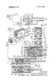
- FIG. 1 is a side elevational view of a terminal block constructed in accordance with and embodying the present invention
- FIG. 2 is a perspective view thereof
- FIG. 3 is a front elevational view, on an enlarged scale, but omitting a showing of the female terminals within the connector;
- FIG. 4 is a sectional view taken along line 4-4 of FIG. 2 and showing the connector assembled with a switch; and 7 FIG. 5 is a fragmentary sectional view taken along line 5-5 of FIG. 4.
- the body 1 comprises a plurality of juxtaposed parallel body sections, in this instance three and generally designated at 3, 5, 7.
- the upper body sections 3, 5 are of equal length and are molded such that their cor responding ends are aligned while the lower body section 7 is longitudinally offset or displaced from the body sections 3, 5.
- Each of the sections 3, 5, 7 is of generally hollow rectilinear shape and includes longitudinal openings 9, 11, 13 extending therethrough; These openings are of similar configuration and so a description of any one of them will suffice for purposes of the present invention, it being understood that like reference numerals indicate like parts with respect to the other openings.
- the opening 9 has top and bottom tapered wall sections 15, 17 extending from the rear end 19 of the body section 3 and terminating in short parallel stretches 21, 21. At the forward edges of the parallel stretches 21, 21 the opening 9 is contoured to provide transverse shoulders 23, 23, and extending from the shoulders to the entrance or front end 25 of the body section 3 are opposed parallel wall portions 26, 26. A short distanceaxially inwardly of the entrance end 25, each body section is formed with a transverse shoulder 27 which, as best seen in FIG. 3, provides a generally cruciform cross-section 29 for that region of the opening 9. Except at the cruciform portion 29, the sides of the opening 9 are parallel, being defined by sidewall surfaces 31, 31.
- the body sections 3, 5 are joined together in the region of their rearends 19 'and'over a region forwardly therefrom toward their entrance ends 25 by body material such that relative flexing of the body sections 3, 5 is permitted.
- the body sections 3, 5 have common coplanar sidewall portions 33, 33 and a common boundary wall portion 35 (FIG. 4), the latter containing the tapers 17, 17 and separating the longitudinal openings 9, 11 of the respective body sections 3, 5.
- the resulting arrangement thus provides a slot 37 intermediate the body sections 3, 5 and running from their entrance ends 25 to the wall portion 35.
- the top wall 39 of the body section 9 integrally includes a tongue 41 which is, in effect, a thickened rear portion of the top wall 39.
- This tongue 41 projects rearwardly beyond the rear end 19- of the body section 7 and is turned upwardly at right angles for integral connection with the lower wall 43 of the body section 7 approximately in vertical alignment with the forward edge of the common wall portion 35.
- the tongue 41 may include a central rib 45 joined to the lower wall 43. It will be seen, therefore, that the arrangement for hingedly joining the body sections 5, 7 thus provides a slot 47 therebetween which allows the body sections space to move toward one another.
- each of the respective openings 9, l l, 13 are female terminals 49, 49, 49 of like construction of known type. Suffice it to say, however, that the terminal 49 is a one piece sheet metal member comprising a leading end 51 and a trailing end 53.
- the leading end 51 is substantially a hollow open-ended rectangle with side walls 55, 55 and relatively narrower end walls 57, 57.
- one of the sidewalls 55 is longitudinally split and cut away in the provision of two inwardly projecting, resilient, spaced apart conviewed from FIG. 5, the indentations would be below the contacts 59, 59.
- the upper wall 55 is provided with an outwardly struck tongue 63 that is resilient and is'adapted to engage the shoulder 23.
- the tongue 63 is resilient so that when the terminal 49 is inserted into the opening 9, 1 1, 13, as the case may be, the tongue 63 will be depressed by engagement with the taper wall portion of the body section and will snap outwardly just as it passes the shoulder 23. This prevents retraction of the terminal from within the body section.
- the forward end shoulder 27 limits the axial advance or forward movement of the terminal into its associated opening 9, 11 or 13.
- the trailing end 53 integrally includes crimping arms 64, 65 for crimping lead wires 67, 67, 67 to the respective terminals such that the insulated lead wires project outwardly from the rear ends 19 of the several body sections 3, 5, 7.
- a typical switch'69 having an actuating button 70 includes three flat terminals 71, 73, 75.
- two of the terminals 71, 73 project from one side of the switch housing while the remaining terminal 75 projects downwardly from the switch body and is bent at a right angle so as to be parallel with the terminals 71, 73.
- the switch terminals 71, 73, 75 engage and make electrical contact with .the several terminals 49 as by a friction fit between each switch terminal and the contacts 59, 59 and indentations 61, 61 on theassociated terminal 49.
- the spacing between the several switch terminals 71, 73, 75 is not uniform among the switches of various manufacturers and may vary to some degree. I-Iowever, insertion of the switch terminals 71, 73, 75 within the terminals 49, 49, 49 is permitted since each of the body sections 3, 5, 7 is capable of a modicum of flexing from their normal or molded relative position.
- An electrical connector comprising a flexible dielectric body having body sections, each body section having a longitudinal opening extending therethrough, the body sections being juxtaposed and each having means in its opening for retaining an electrically conductive terminal therein such that each terminal may be presented to an entrance end of the body for receiving from said entrance end an elongated terminal adapted for engagement with the first-mentioned terminal, said means including transverse shoulder means adjacent to the entrance end of the body section for limiting the insertion of the first-mentioned terminal 4.
- said body sections being spaced apart along portions of their lengths and being integrally joined by body material along other portions of their lengths, a first portion of joining body material forming a common longitudinal wall portions between first and second adjacent body sections, said common wall portion longitudinally separating the openings of said first and second body sections, a second portion of joining body material comprising a tongue that connects a wall of a third body section to a wall of said second body section, said tongue being bent to projecttoward said wall of the second body section, said entrance ends of said first and second body sections being substantially aligned and said entrance ends of said second and third body sections being longitudinally offset, the joiningbody material portions constituting zones of flexure for adjacent body sections that operate to vary the spacing of their entrance ends for accommodation of elongated terminals of varying spacing.
- An electrical connector comprising a flexible dielectric body having parallel'body sections each with a longitudinal opening and entrance and rear ends, two adjacent body sections having corresponding ends respectively juxtaposed and being joined by body material that constitutes a common longitudinal wall portion between the openings of said two body sections, said two body sections being spaced apart from said wall portions to provide a slot extending from said wall portion to one set of corresponding ends of the body sections, an additional body section having a longitudinal opening that extends from an entrance end to a rear end of said additional body section, said additional body section being longitudinally displaced from one of said body sections such that the entrance end of said one body section is longitudinally intermediate the entrance and rear ends of said additional body section, said additional body section being secured to said one body section by a tongue of body material that provides a slot between said additional body section and said one body section, said additional body section having a wall and said tongue projecting rearwardly of said wall and being bent to project toward said one body section for connection therewith, said slots permitting flexing of the body sections relative to one another at the joining regions of
- An electrical connector comprising a dielectric body having hollow juxtaposed body sections with entrance openings facing in the same direction, terminals in the body sections and presented to the respective openings for reception of companion terminals, and means formed by resilient connections of body material between the body sections for providing a modicum of flexing of the body sections to accommodate variations in the spacings of said companion terminals, one of said body sections having a tongue formed by an extension of a wall thereof, said extension being bent remote from said one body section to project toward and join a wall of an adjacent body section to form one of said resilient connections.
Landscapes
- Connector Housings Or Holding Contact Members (AREA)
- Coupling Device And Connection With Printed Circuit (AREA)
Applications Claiming Priority (1)
| Application Number | Priority Date | Filing Date | Title |
|---|---|---|---|
| US12804171A | 1971-03-25 | 1971-03-25 |
Publications (1)
| Publication Number | Publication Date |
|---|---|
| US3701082A true US3701082A (en) | 1972-10-24 |
Family
ID=22433316
Family Applications (1)
| Application Number | Title | Priority Date | Filing Date |
|---|---|---|---|
| US128041A Expired - Lifetime US3701082A (en) | 1971-03-25 | 1971-03-25 | Electrical connector |
Country Status (7)
| Country | Link |
|---|---|
| US (1) | US3701082A (enExample) |
| AU (1) | AU466230B2 (enExample) |
| CA (1) | CA945235A (enExample) |
| DE (1) | DE2213747A1 (enExample) |
| FR (1) | FR2130708B1 (enExample) |
| GB (1) | GB1363984A (enExample) |
| IT (1) | IT952147B (enExample) |
Cited By (6)
| Publication number | Priority date | Publication date | Assignee | Title |
|---|---|---|---|---|
| EP0233558A1 (en) * | 1986-02-07 | 1987-08-26 | Fujitsu Limited | Cable connectors |
| US5067915A (en) * | 1984-10-23 | 1991-11-26 | Siemens Aktiengesellschaft | Plug-in component |
| US5186660A (en) * | 1989-11-09 | 1993-02-16 | Eaton Corporation | Bi-level wiring harness connector |
| US5586915A (en) * | 1994-12-20 | 1996-12-24 | The Whitaker Corporation | Electrical connector with contacts at different insertion depths |
| US5591035A (en) * | 1994-10-06 | 1997-01-07 | The Whitaker Corporation | Electrical connector with shortened contact |
| USD484462S1 (en) | 2001-06-12 | 2003-12-30 | Inarca S.P.A. | Electric connector for power and control lines, particularly for commutators/regulators |
Families Citing this family (3)
| Publication number | Priority date | Publication date | Assignee | Title |
|---|---|---|---|---|
| FR2416569A1 (fr) * | 1978-02-02 | 1979-08-31 | Burndy Corp | Connecteur indirect pour la mise en place de contacts ou de broches dans un panneau de cablage |
| US4389697A (en) | 1979-10-03 | 1983-06-21 | Ferranti Plc | Circuit assembly having a component with leads extending therefrom and a connector both supported on a planar substrate |
| DE9414890U1 (de) * | 1994-09-13 | 1995-05-18 | Siemens AG, 80333 München | Elektrischer Steckverbinder mit einer Verriegelungseinrichtung |
Citations (5)
| Publication number | Priority date | Publication date | Assignee | Title |
|---|---|---|---|---|
| FR1122807A (fr) * | 1955-02-07 | 1956-09-13 | Mayet Ets | Fiche, en particulier pour conducteur électrique souple |
| US2897469A (en) * | 1957-04-09 | 1959-07-28 | Morse Milton | Molded self-grounding electrical plug construction |
| GB1030091A (en) * | 1964-01-15 | 1966-05-18 | Pressac Ltd | An insulating housing for a socket of a pin and socket electric connector |
| FR92979E (fr) * | 1966-05-27 | 1969-01-24 | Proner Sa Ets | Protecteur isolant pour clips de connexion électrique. |
| US3519977A (en) * | 1968-01-11 | 1970-07-07 | Whitaker Cable Corp | High amperage quick disconnect electric coupling structure |
Family Cites Families (3)
| Publication number | Priority date | Publication date | Assignee | Title |
|---|---|---|---|---|
| DE1490522A1 (de) * | 1964-02-22 | 1969-07-03 | Rau Swf Autozubehoer | Steckkupplung fuer elektrische Geraeteanschluesse |
| FR1487487A (fr) * | 1966-05-27 | 1967-07-07 | Proner Sa Ets | Protecteur isolant pour clips de connexion électrique |
| FR2064591A5 (enExample) * | 1969-10-01 | 1971-07-23 | Proner Sa Ets |
-
1971
- 1971-03-25 US US128041A patent/US3701082A/en not_active Expired - Lifetime
-
1972
- 1972-02-22 CA CA135,304A patent/CA945235A/en not_active Expired
- 1972-02-28 AU AU39417/72A patent/AU466230B2/en not_active Expired
- 1972-02-28 GB GB909272A patent/GB1363984A/en not_active Expired
- 1972-03-07 IT IT48820/72A patent/IT952147B/it active
- 1972-03-22 DE DE19722213747 patent/DE2213747A1/de active Pending
- 1972-03-24 FR FR7210536A patent/FR2130708B1/fr not_active Expired
Patent Citations (5)
| Publication number | Priority date | Publication date | Assignee | Title |
|---|---|---|---|---|
| FR1122807A (fr) * | 1955-02-07 | 1956-09-13 | Mayet Ets | Fiche, en particulier pour conducteur électrique souple |
| US2897469A (en) * | 1957-04-09 | 1959-07-28 | Morse Milton | Molded self-grounding electrical plug construction |
| GB1030091A (en) * | 1964-01-15 | 1966-05-18 | Pressac Ltd | An insulating housing for a socket of a pin and socket electric connector |
| FR92979E (fr) * | 1966-05-27 | 1969-01-24 | Proner Sa Ets | Protecteur isolant pour clips de connexion électrique. |
| US3519977A (en) * | 1968-01-11 | 1970-07-07 | Whitaker Cable Corp | High amperage quick disconnect electric coupling structure |
Cited By (8)
| Publication number | Priority date | Publication date | Assignee | Title |
|---|---|---|---|---|
| US5067915A (en) * | 1984-10-23 | 1991-11-26 | Siemens Aktiengesellschaft | Plug-in component |
| EP0233558A1 (en) * | 1986-02-07 | 1987-08-26 | Fujitsu Limited | Cable connectors |
| US4797119A (en) * | 1986-02-07 | 1989-01-10 | Fujitsu Limited | Insulation displacement connection (IDC) type cable connector and a method for assembling a cable thereto |
| US5186660A (en) * | 1989-11-09 | 1993-02-16 | Eaton Corporation | Bi-level wiring harness connector |
| US5591035A (en) * | 1994-10-06 | 1997-01-07 | The Whitaker Corporation | Electrical connector with shortened contact |
| US5586915A (en) * | 1994-12-20 | 1996-12-24 | The Whitaker Corporation | Electrical connector with contacts at different insertion depths |
| USD484462S1 (en) | 2001-06-12 | 2003-12-30 | Inarca S.P.A. | Electric connector for power and control lines, particularly for commutators/regulators |
| USD484461S1 (en) | 2001-06-12 | 2003-12-30 | Inarca S.P.A. | Electric connector for power and control lines, particularly for commutators/regulators |
Also Published As
| Publication number | Publication date |
|---|---|
| DE2213747A1 (de) | 1972-10-12 |
| AU466230B2 (en) | 1973-08-30 |
| CA945235A (en) | 1974-04-09 |
| FR2130708A1 (enExample) | 1972-11-03 |
| FR2130708B1 (enExample) | 1976-01-16 |
| GB1363984A (en) | 1974-08-21 |
| IT952147B (it) | 1973-07-20 |
| AU3941772A (en) | 1973-08-30 |
Similar Documents
| Publication | Publication Date | Title |
|---|---|---|
| US3903385A (en) | Shorting bar switch in electrical connector biasing assembly | |
| FI63643B (fi) | Elektrisk koppling | |
| US3366729A (en) | Electrical connector housing | |
| US3137537A (en) | Separable connector for flat multipleconductor cables | |
| US4083617A (en) | Electrical connector | |
| KR890004498B1 (ko) | 잭-플러그 조립체 | |
| US4560226A (en) | Electrical connector member and contactor unit | |
| US4367908A (en) | Electrical connector coupling | |
| US3731259A (en) | Electrical connector | |
| US5697815A (en) | Electrical connectors | |
| US3676833A (en) | Hermaphorodite electrical connector | |
| US3275765A (en) | Electrical connecting and switch device | |
| EP0021731A1 (en) | Electrical contact member and connector including such contact members | |
| KR950034907A (ko) | 암형단자 및 이를 사용한 컨넥터 | |
| ES367845A1 (es) | Un dispositivo de bloque de union de circuito, para inter- conectar una pluralidad de conductores de circuito en un mo-delo de circuito predeterminado | |
| US3789343A (en) | Electrical connector | |
| US4066325A (en) | Electrical connector for printed circuit board | |
| US3701082A (en) | Electrical connector | |
| US10763603B2 (en) | Electronic card connector and electronic card connector assembly thereof | |
| EP0740372B1 (en) | Electrical connector | |
| KR950007195A (ko) | 개선된 단자 래칭 장치를 갖춘 전기 커넥터 | |
| IL34811A (en) | Tiny electrical connector | |
| SE8601309L (sv) | Elektriskt kopplingsdon | |
| US4056300A (en) | Terminal connector with stress relief | |
| US4583640A (en) | Packaging arrangement for electrical connectors |