US3685471A - Automatic trouser fly fabric feeding machine and method - Google Patents
Automatic trouser fly fabric feeding machine and method Download PDFInfo
- Publication number
- US3685471A US3685471A US75996A US3685471DA US3685471A US 3685471 A US3685471 A US 3685471A US 75996 A US75996 A US 75996A US 3685471D A US3685471D A US 3685471DA US 3685471 A US3685471 A US 3685471A
- Authority
- US
- United States
- Prior art keywords
- fabric
- piece
- fly
- stack
- fly fabric
- Prior art date
- Legal status (The legal status is an assumption and is not a legal conclusion. Google has not performed a legal analysis and makes no representation as to the accuracy of the status listed.)
- Expired - Lifetime
Links
Images


Classifications
-
- A—HUMAN NECESSITIES
- A41—WEARING APPAREL
- A41H—APPLIANCES OR METHODS FOR MAKING CLOTHES, e.g. FOR DRESS-MAKING OR FOR TAILORING, NOT OTHERWISE PROVIDED FOR
- A41H37/00—Machines, appliances or methods for setting fastener-elements on garments
- A41H37/06—Setting slide or glide fastener elements
-
- D—TEXTILES; PAPER
- D05—SEWING; EMBROIDERING; TUFTING
- D05B—SEWING
- D05B33/00—Devices incorporated in sewing machines for supplying or removing the work
- D05B33/006—Feeding workpieces separated from piles, e.g. unstacking
-
- D—TEXTILES; PAPER
- D05—SEWING; EMBROIDERING; TUFTING
- D05B—SEWING
- D05B35/00—Work-feeding or -handling elements not otherwise provided for
- D05B35/06—Work-feeding or -handling elements not otherwise provided for for attaching bands, ribbons, strips, or tapes or for binding
- D05B35/064—Work-feeding or -handling elements not otherwise provided for for attaching bands, ribbons, strips, or tapes or for binding for attaching slide fasteners
-
- B—PERFORMING OPERATIONS; TRANSPORTING
- B65—CONVEYING; PACKING; STORING; HANDLING THIN OR FILAMENTARY MATERIAL
- B65H—HANDLING THIN OR FILAMENTARY MATERIAL, e.g. SHEETS, WEBS, CABLES
- B65H2301/00—Handling processes for sheets or webs
- B65H2301/30—Orientation, displacement, position of the handled material
- B65H2301/33—Modifying, selecting, changing orientation
- B65H2301/332—Turning, overturning
- B65H2301/3321—Turning, overturning kinetic therefor
- B65H2301/33212—Turning, overturning kinetic therefor about an axis parallel to the direction of displacement of material
-
- B—PERFORMING OPERATIONS; TRANSPORTING
- B65—CONVEYING; PACKING; STORING; HANDLING THIN OR FILAMENTARY MATERIAL
- B65H—HANDLING THIN OR FILAMENTARY MATERIAL, e.g. SHEETS, WEBS, CABLES
- B65H2301/00—Handling processes for sheets or webs
- B65H2301/30—Orientation, displacement, position of the handled material
- B65H2301/33—Modifying, selecting, changing orientation
- B65H2301/332—Turning, overturning
- B65H2301/3322—Turning, overturning according to a determined angle
- B65H2301/33222—90°
-
- D—TEXTILES; PAPER
- D05—SEWING; EMBROIDERING; TUFTING
- D05D—INDEXING SCHEME ASSOCIATED WITH SUBCLASSES D05B AND D05C, RELATING TO SEWING, EMBROIDERING AND TUFTING
- D05D2207/00—Use of special elements
- D05D2207/02—Pneumatic or hydraulic devices
- D05D2207/04—Suction or blowing devices
Definitions
- Boler Attorney-Meech & Field ABSTRACT An apparatus and method for automatically feeding individual pieces of fly fabric from a stack of such pieces to a zipper sewing machine, wherein the pieces of fabric in the stack havedifferent shades on their opposite sides and it is desired to feed continuously to the zipper sewing machine successive pieces of the fly fabric with the sides thereof having the same shade oriented in a predetermined position. More specifically the method involves sensing the shade of one of the sides of a given piece of fly fabric in a feed hopper, removing the pieces of fly fabric from the feed hopper and then rotating the piece of fly fabric approximately 90 in response to the sensing step so as to orient the piece of fly fabric with its sensed side disposed in a predetermined position for subsequent feeding to the zipper sewing machine.
- trouser fly closure units The general field of producing trouser fly closure units is well known. Specific designs and techniques for producing trouser fly closure units are described, for example, in US. Pat. No. 2,079,834, No. 2,155,795, No. 2,549,496, No. 2,623,214, No. 2,697,277, No. 2,731,643, No. 2,823, 388, No. 3,003,445, No. 3,081,462, and No. 3,263,238. In the early days of the art of producing trouser fly closure units, the units were normally individually fabricated by sewing an individual slide fastener chain and its attached stringers to an individual fly strip tape to produce a single trouser fly closure unit.
- trouser fly closure units were automated and made continuous as described, for example, in U.S. Pat. No. 3,263,238 in which a continuous slide fastener chain and its attached stringers are sewn together with a continuous fly fabric tape to produce a continuous trouser fly closure strip which can then be subsequently cut into desired lengths to produce individual trouser fly closure units.
- the trouser fly closure units are normally produced by an automatic continuous process utilizing prime fabric material for the continuous fly fabric tape employed in the manufacture of such units.
- prime fabric material for the continuous fly fabric tape employed in the manufacture of such units.
- garments such as dungarees, levis, work pants, overalls, etc; a considerable amount of scrap material is left after the individual patterns are cut from the prime fabric material utilized to produce such garrnents.
- this scrap material could be utilized for the fly fabric material in an automatic process, instead of the prime fly fabric material, to thereby achieve considerable savings in the manufacture of trouser fly closure units.
- the present invention relates to a novel apparatus and method for automatically feeding individual pieces of fly fabric from a stack of such pieces to a zipper sewing machine wherein a continuous slide fastener chain or zipper with its attached stringers is sewn to individual pieces of fly fabric to produce a continuous strip comprising the continuous slide fastener chain and a series of successive individual pieces of fly fabric.
- the pieces of fly fabric normally employed have different shades of color on their opposite sides.
- the present invention is particularly applicable to producing trouser fly closure units for garments produced in large quantities such as dungarees, levis, work pants, overalls, etc.
- the present invention makes practical and economical for the first time the utilization of scrap fabric material from the cutting of the original garment for subsequent use in an automated method for producing trouser fly closure units.
- pieces of fabric of the size desired for the fly fabric of the trouser fly closure unit are cut and formed into stacks.
- the pieces of fly fabric will be cut so as to produce pairs of the fly fabric pieces in which one of the pieces of the pair will have its dark shade surface on the top side and its light shade surface on the bottom side, whereas the other fabric piece will have its light shade surface on the top and its dark shade surface on the bottom.
- the present invention provides an apparatus and method for automatically feeding individual pieces of 1 fly fabric from a stack of such pieces to a zipper sewing machine despite the fact that the pieces of fly fabric in the stack may have different shades on their opposite sides and may be arranged in any particular order.
- the novel technique of the present invention it is possible to feed continuously to the zipper sewing machine successive pieces of fly fabric with the sides thereof having the same shade always oriented in the desired predetermined position.
- the method of the present invention involves the step of sensing the shade of one of the sides of a given piece of fly fabric in a feed hopper, then removing this piece of fly fabric from the feed hopper and rotating the piece of fly fabric approximately ninety degrees in response to the sensing step so as to orient the piece of fly fabric with its sensed side disposed in the desired predetermined position for subsequent feeding to the zipper sewing machine.
- a major object of the present invention is to provide an automatic essentially continuous process for producing trouser fly closure units in which fly fabric pieces cut from scrap garment material may be utilized in the manufacture of trouser fly closure units.
- FIG. 1 is a diagrammatic illustration of the basic apparatus of the present invention.
- FIG. 2 is a side elevational view in partial cross-section showing the hopper feed unit of the present apparatus.
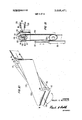
- FIG. 3 is a side elevational view of the pickbar device of the present invention which is utilized to partially removed an individual piece of fly fabric from a stack of such pieces.
- FIG. 4 is an enlarged view in perspective of a part of the pickbar of FIG. 3 showing the arrangement of teeth on the pickbar.
- FIGS. 5, 6, 7 and 8 are side elevational views in partial cross-section showing the operation of top and bottom shuttles for aligning the piece of fly fabric which has been partially separated from the stack by the pickbar described in FIGS. 3 and 4.
- FIG. 9 is a perspective view of the hopper transport device which moves the separated fly fabric to the fabric orientation machine.
- FIG. 10 is a perspective view of the continuous belt and pulley device designed to orient individual pieces of fly fabric.
- FIG. 11" is a perspective view of the fabric orientation machine including the continuous belt and pulley device shown in FIG.'10.
- FIG. 12 is a side elevational view in partial cross-section of the sewing feed machine of the present invention which feeds individual pieces of fly fabric to the sewing machine.
- FIG. 13 is a top elevational view showing the individual pieces of fly fabric stitched to a continuous slide fastener chain and its attached stringers.
- FIG. 14 is a perspective view of the basic apparatus of the present invention.
- the present invention as mentioned previously is particularly useful for producing trouser fly closure units especially of the type used in dungarees, levies, work pants, overalls, etc.
- these types of garments are normally constructed of a blue colored denimfabric in which the outer surface or side is a dark blue and the inner surface or side is a light blue (actually, normally a combination of dark blue and white threads).
- the following description of the apparatus a and method of the present invention will therefor be discussed in the context of pieces of fly fabric in which one side or surface is dark blue and the other side or surface is light blue.
- reference numeral 10 designates the hopper feed machine of the present invention into which are placed stacks of individual pieces of fly fabric and from which individual pieces of fly fabric are successively and essentially continuously removed and passed to a fabric orientation machine designated by the reference numeral 12.
- fabric orientation machine 12 each individual piece of fly fabric is rotated approximately ninety degrees so as to position its side or surface having a given shade in a desired predetermined position.
- Reference numeral 14 designates generally a sensing-actuating device which performs severalfunctions.
- First sensing-actuating device 14 senses the particular shade of blue on the front surface of the outer piece of fabric removed from hopper feed machine 10 to determine whether this side is dark blue or light blue.
- sensing-actuating device 14 rotates the piece of fly fabric ninety degrees in one direction or the other depending upon whether its sensed side' was dark blue or light blue.
- the piece of fly fabric exiting from fabric orientation machine 12 always has either its dark blue surface or its light blue surface face up.
- the dark blue surface is face up.
- sensing-actuating device 20 which performs several functions. First, it is designed to sense the presence or absence of a piece of fly fabric in the sewing machine. When sensing-actuating device 20 senses the absence of a piece of fly fabric in sewing machine 18 it actuates sewing feed machine 16 so as to transfer or pass another piece of fly fabric from sewing feed machine 16 to sewing machine 18.
- Sensing-actuating device 22 is designed to sense the presenceor absence of a piece of fly fabric in sewing feed machine 16. When sensingactuating device 22 senses the absence of a piece of fly fabric in sewing feed machine 16, it actuates hopper feed machine 10 to thereby pass or transfer a piece of fly fabric from hopper feed machine 10 through fabric orientation machine 21 to sewing feed machine 16. 7
- FIG. 2 shows in detail the design and operation of hopper feed machine 10.
- Reference numeral 24 designates a stack of fly fabric pieces arranged in hopper 26. Generally each stack of fly fabric pieces will comprise about 54 individual pieces. Each of these pieces of fly fabric will normally be about 2 to 2-% inches in width and will have a length which depends upon the length of the trouser fly closure unit desired. It is to be noted that in FIG. 2 the pieces of fly fabric are arranged such that their short side, namely the side which is 2 to 246 inches, is on the side exposed to view in FIG. 2. Stack 24 of the individual pieces of fly fabric are supported on one of their ends by feed support means 28., which is designed to move laterally to the left in FIG. 2 on rod 30. Feed support means 28 not only supports one side of the stack 24 but it is also designed by means of an applied force 32 to move stack 24 to the left in FIG. 2 as successive, individual pieces of fly fabric are removed from hopper 26.
- base plate 34 Disposed at thefront end of hopper 26 is base plate 34 which is designed to support and hold the stack 24 in hopper 26.
- lower shuttle 36 Disposed between the front end of hopper 26 and base plate 34 is lower shuttle 36 which is slidably movable in a vertical plane between the front end of hopper 26 and base plate 34.
- the length of the front opening of hopper 26 and lower shuttle 36 is approximately equal to the length of fly fabric material which is to be processed through hopper feed machine 10.
- Lower shuttle 36 is operated by' double acting cylinder 38 which moves lower shuttle 36 either up or down in response to sensing-actuating device 22 described in FIG. 1. The action of double acting.
- Connecting arm 44 connects the operating arm of double acting cylinder 38 with lower shuttle 36 and is designed to move slidably on guide pin 40.
- upper shuttle 46 Disposed on the upper front end of hopper 26 is upper shuttle 46 which like lower shuttle 36 extends lengthwise across the entire front of hopper 26.
- Upper shuttle 46 is operated by double acting cylinder 48 in a manner similar to the operation of lower shuttle 36 and double acting cylinder 38.
- upper shuttle 46 is designed to move up and down in a vertical plane in front of hopper 26.
- the operation of upper shuttle 46 by double acting cylinder 48 is guided by guide pin 50 which is rigidly attached to support base 52.
- Connecting arm 54 connects the operating arm of double acting cylinder 48 and upper shuttle 46.
- Photo electric cell 54 Disposed in spaced relationship with respect to the front of hopper 26 and the front of stack 24 is a photo electric cell 54 which comprises a portion of sensingactuating device 14.
- Photo electric cell 54 is comprised of light source 56 and light detecting cell 58.
- a beam of light 60 is emitted from light source 56 which impinges upon the front surface of the front piece of fly fabric from stack 24.
- Reflected light beam 62 is received by light detecting cell 58 which is designed to determine or detect whether the front surface of the front piece of fly fabric in stack 24 is either dark blue or light blue.
- Reference numerals 88, 90 and 100 shown in FIG. 2 relate to a hopper transport mechanism which will be described in detail in connection with FIG. 9.
- Reference numeral 64 designates a pick bar device which is utilized to separate and remove the top edge of the front piece of fly fabric from stack 24.
- pick bar device 64 comprises a crankshaft 66 which rotates in a counterclockwise direction in circle 68 and which is operated by motor means 69. Attached in movable relation to crankshaft 66 is crank connecting rod 70.
- Linkage 74 is connected through pin 76 to crank connecting rod 70 in its central area. The other end of linkage 74 is pivotally connected to support base 78 by pin 80.
- pick bar 82 At the end of crank connecting rod 70 opposite crankshaft 66 is pick bar 82 which is provided with a series of teeth 84 shown in greater detail in FIG.
- pick bar device 64 includes a second crank connecting rod 70, linkage 74, pin 76, support base 78 and pin 80 operatively connected at the other end of pick bar 82, for support purposes. It will be noted from the design of pick bar device 64 shown in FIG. 3 that as crankshaft 66 rotates in a counterclockwise direction, pick bar 82 will move forward and downward in the first phase of the cycle and in the second phase of the cycle will move upward and backward.
- the teeth 84 of pick bar 82 are designed to engage the upper portion of the front piece of fly fabric in hopper 26 to thereby separate and remove the upper portion thereof from the stack 24.
- reference numeral 86 designates the front piece of fly fabric in stack 24 which has been separated at its upper end from stack 24 as described in the discussion with respect to FIGS. 3 and 4.
- FIG. 6 this drawing illustrates one step in the operation of upper shuttle 46. It will be noted in FIG. 6 (as compared with FIG. 5) that upper shuttle 46 has been moved vertically downward to its lower position as a result of the operation of double acting cylinder 48. The purpose of this action of upper shuttle 46 is to separate or segregate fly fabric piece 86 completely from stack 24.
- FIG. 7 illustrates one of the operating steps of lower shuttle 36. It will be noted in FIG. 7 (as compared with FIG.
- FIG. 8 this drawing illustrates the second step in the operation of lower shuttle 36. It will be noted in FIG. 8 that lower shuttle 36 has been moved vertically downward to assume the same position as it was in FIG. 5.
- FIG. 9 shows in a front perspective view the same fly fabric piece 86 which had been shown in side view in FIG. 8. It will be noted that fly fabric piece 86 rests flush against the front surface of upper shuttle 46.
- double acting cylinder 88 which is attached by means of support arm 90 to base plate 34.
- guide rods 92 and 94 Rigidly connected to support arm 90 are guide rods 92 and 94 upon which slide 96 is disposed to move horizontally back and forth in slidably movable relationship to guide rods 92 and 94.
- Pin 98 is connected to slide 96 and is disposed in a vertical direction in FIG. 9.
- Mounted on pin 98 is pawl 100 which is designed to pivot in a horizontal plane about pin 98.
- Arm 102 is associated with double acting cylinder 88 and is pivotally connected at its other end to pawl 100 by pin 99.
- cylinder arm 102 extends as a result of the operation of double acting cylinder 88.
- cylinder arm 102 moves to the left in FIG. 9.
- pawl 100 pivots about pin 98 attached to slide 96 until pawl 100 contacts fly fabric piece 86 and forces it back against the surface of upper shuttle 46.
- cylinder arm 102 continues its extension to the left pawl 100 carries the fly fabric piece 86 to the left by moving it along the surface of upper shuttle 46.
- FIG. 10 illustrates the basic design and operation of fabric orientation machine 12. Due to the operation of pawl 100 fly fabric piece 86 is moved to the left into the input opening of belt-pulley combination 104.
- Belt-pulley combination 104 comprises a first continuous belt 106 and a second continuous belt 108.
- Belt-pulley combination 104 also comprises two sets of pulleys 110 and 111.
- Pulley set 110 comprises pulley 112 and pulley 1 l4
- pulley set 111 comprises pulley 116 and pulley 118.
- belt 106 is designed to operate with pulleys 114 and 118 and belt 108 is designed to operate with pulleys 112 and 116.
- the belt-pulley combination 104 is operated by a conventional motor means (not shown in the drawing) operatively connected to pulley set 111 comprising pulley 116 and 118.
- FIG. 11 provides additional detail with respect to the design and operation of fabric orientation machine 12. It will be noted from FIG. 11 that pulley set 110 comprising pulley 112 and 114 is mounted in supports 120 and 122 which are connected to sprocket 124 which in turn is mounted in housing 126. Sprocket 124 is disposed within housing 126 so as to be rotatably movable therein about its axis. Associated with sprocket 124 is sprocket 128, double acting cylinder 130, connecting rod 132 and roller chain 134. Thus,'the movement of connecting rod 132 ,by double acting cylinder 130 I operates roller chain 134 which in turn rotates sprocket 124.
- Double acting cylinder 130 is actuated by sensingactuating device 14 to thereby rotate sprocket 124 90 in one direction or the other depending upon the signal .sent to double acting cylinder 130 by sensing-actuating device 14.
- the at-rest position of sprocket 124 is such that pulley set 110 comprising pulleys 112 and 114 is disposed in a vertical position with respect to the longitudinal axes of pulleys 112 and 114.
- Pulley set 11 1 comprising pulleys 116 and 118 are disposed in the same position throughout the entire operationof fabric orientation machine 12.
- the pulleys 116 and 118 are connected through drive shafts.(not shown) attached to support base 136 and support base 138.
- fly fabric piece 86 is then fed into the input end or opening of belt-pulley combination 104.
- Double acting cylinder 130 is actuated by sensingactuating device 14 to rotate sprocket 124 ninety degrees from its at-rest position in a counterclockwise direction to position pulley set 110 in the position shown in FIG. 10.
- fly fabric piece 86 is passed through the space between continuous belts 106 and 108 it is likewise turned 90 in a counterclockwise direction such that when it exits from the output end or opening belt-pulley combination 104 its dark blue surface is face up and in the desired position to eventually be fed through sewing feed machine 16 to sewing machine 18.
- fabric orientation machine 12 would be actuated by sensing-actuating device 14 to rotate sprocket 124 ninety degrees in a clockwise direction such that when fly fabric piece 86 exited from the output end or opening of belt-pulley combination 104, its dark blue surface would be face up and in the desired position to be fed through sewing feed machine 16 to sewing machine 18.
- upper shuttle 46 is raised vertically upward to its upper position by double acting cylinder 48.
- FIG. 12 this illustration shows the design of sewing feed machine 16.
- Reference numeral 140 designates a tray which comprises a bottom surface 142 and side pieces 144 and is open at both of its ends. Disposed above tray 140 is continuous belt 146 which rotates about pulleys 148 and 150 which are disposed respectively on shafts 152 and 154. Motor means 156 is operatively connected to sprocket 158 through shaft 160 and operates roller chain 162 which drives pulley 150 which in turn moves belt 146 in a clockwise direction as shown in FIG. 12. Sewing feed machine 16 through which a light beam may be passed.
- Light source 168 is disposed beneath tray and designed to pass a light beam through hole-166.
- light detecting cell 170 Disposed above tray 140 is light detecting cell 170 which is designed to receive the light beam emitted by light source 168.
- Light source 168 and light detecting cell 170 comprise a photo electric cell designed to detect the presence or absence of a piece of fly fabric in sewing feed machine 16 in tray 140 thereof.
- a slot 172 is cut into the bottom tray 140 through which stop bar 174 may be raised or lowered by the action of double acting cylinder 176.
- the continuous belt 146 moving in a clockwise direction receives the piece of fly fabric 86 being discharged from fabric orientation machine 12 and moves it along the bottom surface 142 of tray 140 until it reaches the point where stop bar 174 is disposed.
- stop bar 174 is moved vertically up into slot 172 to thereby stop the movement of fly fabric piece 86 at that point as it moves along bottom surface 142 of tray 140.
- the upward movement of stop bar 174 is designed to also raise slightly pulley 148 to disengage its contact with fly fabric piece 86.
- stop bar 174 When sensing-actuating device 20 detects the absence of a piece of fly fabric in sewingmachine 18, a signal is sent to double acting cylinder176 to actuate stop bar 174. In this case stop bar 174 will be moved vertically downward out of the way of fly fabric piece 86 and belt 146 such that fly fabric piece 86 is then passed by the action of belt 146 through the tray 140v for delivery into sewing machine 18. When stop bar 174 is moved vertically downward it also lowers slightly pulley 148 so that belt 146 again contacts fly fabric piece 86 to thereby move it from sewing feed machine 16 to sewing machine 18.
- stop bar 174 After fly fabric piece 86 passes from sewing feed machine 16 to sewing machine 18 stop bar 174 returns to its'raised stop position within slot 172 in order to stop the next piece of fly fabric at this point as it passes from fabric orientation machine 12 into the sewing feed machine 16.
- the photo electric cell comprising light source 168 and light detecting cell 170 (which comprises a portion of sensing-actuating device 22) detects the absence of a piece of fly fabric in sewing feed machine 16 it sends a signal to hopper feed machine 10 to thereby actuate the operation of hopper feed machine 10 to separate and remove another piece of fly fabric for passage through fabric orientation machine 12 to sewing feed machine 16.
- the sensing-actuating devices of the present invention may be constructed of conventional equipment.
- photoelectric cells may be conveniently used as the sensing devices.
- the actuating devices may be operated electrically, pneumatically or mechanically as desired.
- FIG. 13 shows a section of the trouser fly closure unit product produced by the present invention.
- the product comprises (with respect to the portion shown) fly fabric pieces 178, 180 and 182 which are sewn to a continuous slide fastener chain 184 which comprises chain 186 and its associated stringers 188 and 190.
- Continuous slide fastener chain 184 is stitched to fly fabric pieces 178, 180 and 182 by two rows of stitching designated by the reference numeral 192.
- Sewing machine 18 utilized in the method of the present invention may be any of the conventional sewing machines utilized in the trouser fly closure unit art which are adapted to sew a continuous slide fastener chain to fly fabric material. It is not necessary for the purposes of this invention to describe in detail the well known operation and design of such sewing machines.
- FIG. 14 presents a perspective view of the basic apparatus of the present invention to assist in the understanding of the inter-relationship between hopper feed machine 10, fabric orientation machine 12, sewing feed machine 16 and sewing machine 18.
- reference numeral 194 designates the needles of sewing machine 18
- reference numerals 196 and 198 designate,- respectively, a light source and a light detecting cell which make up the photo electric cell (forming a portion of sensing-actuating device 20) which detects the presence or absence of a piece of fly fabric under needles 194 of sewing machine 18.
- this photo electric cell and the photo electric cell in sewing feed machine 16 both detect the absence of a piece of fly fabric, they are designed to shut off the sewing machine and stop the movement of the continuous zipper chain into sewing machine 18 to avoid wasting the zipper chain.
- the sensing step of the present invention which is designed to detect different shades may likewise be designed to detect not only different colors or shades of surfaces but other surface characteristics such as smoothness, roughness and the like.
- the sewing feed machine 16, for example, described in connection with the present invention is not an essential step or device for the purposes of the present invention (i.e., it would be possible to pass the oriented piece of fly fabric directly from fabric orientation machine 12 to sewing machine 18); however, in the preferred method of operation of the present invention, sewing feed machine 16 is utilized.
- Apparatus for feeding from a stack individual pieces of fly fabric for zippers which have different shades on their opposite sides to a sewing machine for attaching a zipper chain to said pieces of fly fabric which comprises a hopper adapted to hold a stack of said pieces of fabric and having a front end and a rear end,
- a pick bar provided with a series of teeth designed to engage individual pieces of fly-fabric and disposed at the front end of said hopper
- a first actuating means designed to operate said pick bar, said first shuttle and second shuttle to thereby separate and remove said piece of fly fabric from said stack and said hopper,
- a transfer means adapted to move a piece of fly fabric which has been separated and removed from said stack and hopper to an input opening between said belts at the first set of pulleys
- a second actuating means for operating said rotating means in response to said sensing means whereby pieces of fly fabric are delivered from an output opening between said belts at said second set of pulleys at a predetermined orientation with respect to the shades of the two sides of said pieces of fly fabric for feeding to said sewing machine.
- Apparatus according to claim 1 which also includes a second feeding means disposed between the output opening between said belts at said second set of pulleys and said sewing machine which comprises a tray, an endless movable belt disposed within and above the bottom surface of said tray adapted to move a piece of said fly fabric along the bottom of said tray,
- a stop bar disposed generally below said tray
- a second sensing means designed to determine the presence or absence of a piece of said fly fabric in said sewing machine
- a third actuating means for operating said stop bar in said second feeding means in response to said second sensing means to thereby permit a piece of said fly fabric to be fed from said second feeding means to said sewing machine
- a third sensing means designed to determine the presence or absence of a piece of said fly fabric in said second feeding means and designed to actuate said first actuating means.
- a device for separating individual pieces of fabric from a stack of such pieces which comprises a crank connecting rod, a crankshaft operatively connected to one end of said crank connecting rod, a rigid linkage, a support base, a pin connecting one end of said rigid linkage withthe middle section of said crank connecting rod, a second pin connecting the other end of said rigid linkage with said support base, a pick bar attached at the other end of said crank connecting rod, a series of teeth disposed along one edge of said pick bar designed to pick an individual piece of fabric from said stack, and means for rotating said crankshaft whereby saidpick bar moves generally in a two phase cycle in which in the first phase of the cycle the bar moves toward and to the stack of fabric pieces and downwardly to partially separate a piece of fabric from said stack and in the second phase of the cycle the pick bar moves upwardly and away from said piece of fabric thereby disengaging the teeth on said pick bar from said piece of fabric.
- a device in accordance with claim 3 which also includes a first shuttle disposed above said pick bar, a second shuttle disposed below said pick bar, means for raising and lowering said first shuttle and means for raising and lowering said second shuttle, which combination of elements is designed to separate a single piece of fly fabric from saidstack.
- a method for feeding from a stack individual pieces of fly fabric for zippers which have different shades on their opposite sides to a sewing process for attaching a continuous zipper chain to said pieces of fly fabric which comprises sensing the shade of a given piece of fly fabric in said stack on one of its sides, I v removing said piece of fly fabric from said stack, rotating said piece of fly fabric approximately about its linear axis in response to said sensing step to thereby orient said piece of fly fabric ,in a predetermined position with respect to the shade of the sensed side of said piece of fly fabric, feedingsaid oriented piece of fly fabric to said sewing process, and sewing the fed piece of fly fabric to a zipper.
- a method for feeding from. a stack individual pieces of fly. fabric for zippers which have different shades on their opposite sides to a sewing process for attaching a continuous zipper chain to said pieces of fly fabric which comprises sensing the shade of a given piece of fly fabric in said stack on one of its sides,
Landscapes
- Engineering & Computer Science (AREA)
- Textile Engineering (AREA)
- Sewing Machines And Sewing (AREA)
- Sheets, Magazines, And Separation Thereof (AREA)
Applications Claiming Priority (1)
| Application Number | Priority Date | Filing Date | Title |
|---|---|---|---|
| US7599670A | 1970-09-28 | 1970-09-28 |
Publications (1)
| Publication Number | Publication Date |
|---|---|
| US3685471A true US3685471A (en) | 1972-08-22 |
Family
ID=22129261
Family Applications (1)
| Application Number | Title | Priority Date | Filing Date |
|---|---|---|---|
| US75996A Expired - Lifetime US3685471A (en) | 1970-09-28 | 1970-09-28 | Automatic trouser fly fabric feeding machine and method |
Country Status (9)
| Country | Link |
|---|---|
| US (1) | US3685471A (fr) |
| AR (1) | AR193210A1 (fr) |
| BE (1) | BE773104A (fr) |
| CA (1) | CA943152A (fr) |
| DE (1) | DE2148460A1 (fr) |
| ES (1) | ES395464A1 (fr) |
| FR (1) | FR2108634A5 (fr) |
| GB (1) | GB1305340A (fr) |
| IT (1) | IT940951B (fr) |
Cited By (20)
| Publication number | Priority date | Publication date | Assignee | Title |
|---|---|---|---|---|
| US4527792A (en) * | 1981-08-29 | 1985-07-09 | Licentia-Patent-Verwaltungs Gmbh | Apparatus for changing the direction of motion of letters and similar rectangular pieces of mail |
| US4608745A (en) * | 1983-10-17 | 1986-09-02 | Yoshida Kogyo K. K. | Method of attaching fly strips to a slide fastener chain |
| US4641827A (en) * | 1983-06-02 | 1987-02-10 | Richard R. Walton | Fabric pickup and the like |
| US4644886A (en) * | 1984-08-23 | 1987-02-24 | Yoshida Kogyo K. K. | Method and apparatus for attaching fly strips to a slide fastener chain |
| US4645193A (en) * | 1984-05-30 | 1987-02-24 | Richard R. Walton | Fabric pickup and the like |
| US4660821A (en) * | 1983-06-08 | 1987-04-28 | Yoshida Kogyo K.K. | Method of and apparatus for attaching fly strips to a slide fastener chain |
| US4705157A (en) * | 1986-06-09 | 1987-11-10 | Bell & Howell Company | Article turning assembly |
| US4892298A (en) * | 1983-06-02 | 1990-01-09 | Richard R. Walton | Device and method for pickup of sheet-form flexible fabric or the like |
| US5146860A (en) * | 1990-10-19 | 1992-09-15 | Gunze Limited | Sewing and stacking apparatus |
| US5967505A (en) * | 1997-03-21 | 1999-10-19 | Levi Strauss & Co. | Automatic feeder and inverter for fabric workpieces |
| US20040084279A1 (en) * | 2002-11-04 | 2004-05-06 | Kimberly-Clark Worldwide, Inc. | Orientation detection and control system |
| US20040084282A1 (en) * | 2002-11-04 | 2004-05-06 | Kimberly-Clark Worldwide, Inc. | Automatic repacking and accumulation system |
| US20040084468A1 (en) * | 2002-11-04 | 2004-05-06 | Kimberly-Clark Worldwide, Inc. | Metering drum for an automatic accumulation system |
| US20040086372A1 (en) * | 2002-11-04 | 2004-05-06 | Kimberly-Clark Worldwide, Inc. | Positioning system for an automatic accumulation system |
| US20040084280A1 (en) * | 2002-11-04 | 2004-05-06 | Kimberly-Clark Worldwide, Inc. | Conveyor system for an automatic accumulation system |
| US20050076617A1 (en) * | 2003-10-08 | 2005-04-14 | Kimberly-Clark Worldwide, Inc. | Multi-product accumulating and packing system |
| US20090314611A1 (en) * | 2008-06-20 | 2009-12-24 | Pitney Bowes Inc. | Reconfigurable transport system |
| US20140116844A1 (en) * | 2012-10-31 | 2014-05-01 | Detlef Schulze-Hagenest | Sheet inverter and method for inverting a sheet |
| US9394115B2 (en) * | 2012-09-17 | 2016-07-19 | Xerox Corporation | Dynamic reconfigurable in-line inverting and bypass system |
| CN110662862A (zh) * | 2017-05-22 | 2020-01-07 | Ykk株式会社 | 遮布的缝边装置 |
Families Citing this family (6)
| Publication number | Priority date | Publication date | Assignee | Title |
|---|---|---|---|---|
| JPS5172591A (ja) * | 1974-12-20 | 1976-06-23 | Taichi Kaneda | Danboorushiitokyoseihoho |
| DE3374700D1 (en) * | 1983-07-21 | 1988-01-07 | Akab Of Sweden Ab | Method for automatic sewing of zippers and an automatic sewing machine for accomplishing the method |
| US4611546A (en) * | 1984-08-23 | 1986-09-16 | Yoshida Kogyo K. K. | Apparatus for attaching fly strips to a slide fastener chain |
| US4576104A (en) * | 1984-09-14 | 1986-03-18 | Yoshida Kogyo K. K. | Method and apparatus for attaching fly strips to a slide fastener chain |
| DE19542846A1 (de) * | 1995-11-17 | 1997-05-22 | Spuehl Ag | Federtransporteinrichtung mit Servo-Antrieb |
| IT202200002042A1 (it) * | 2022-02-04 | 2023-08-04 | Tt Italy S P A | Apparato per la manipolazione di pan di spagna |
Citations (10)
| Publication number | Priority date | Publication date | Assignee | Title |
|---|---|---|---|---|
| US1761794A (en) * | 1928-06-08 | 1930-06-03 | Peters Mach Co | Carton-blank separating and feeding mechanism |
| US2947406A (en) * | 1958-12-31 | 1960-08-02 | Pitney Bowes Inc | Letter inverter |
| GB845689A (en) * | 1957-06-21 | 1960-08-24 | Siemens Ag | Improvements in or relating to apparatus for orientating disorientated articles of mail |
| US3029726A (en) * | 1958-08-08 | 1962-04-17 | Addressograph Multigraph | Printing machines |
| US3172655A (en) * | 1962-01-04 | 1965-03-09 | Berkley Machine Co | Mechanism for removing blanks or sheets from a stack |
| CH389535A (de) * | 1962-02-13 | 1965-03-31 | A & H Eichholzer Ag | Verfahren zum Annähen von Reissverschlüssen an Gewebe- oder Lederstücken, die zur serienweisen Herstellung, z.B. von Kleidungsstücken, Sport-, Reise- und Gebrauchsartikeln, wie Taschen, Rucksäcken, Etuis usw. dienen, sowie Mittel zur Ausübung des Verfahrens |
| US3253824A (en) * | 1964-11-18 | 1966-05-31 | L & L Mfg Inc | Apparatus for separating pieces from a stack, and the like |
| US3280995A (en) * | 1964-10-30 | 1966-10-25 | William C Barkley | Apparatus for inverting articles |
| US3298498A (en) * | 1965-06-04 | 1967-01-17 | Union Special Machine Co | Work piece inverter conveyor |
| US3355165A (en) * | 1965-04-20 | 1967-11-28 | L & L Mfg Inc | Fabric stretching and/or alternatelyreversing mechanism for separating fabric pieces from a stack thereof |
-
1970
- 1970-09-28 US US75996A patent/US3685471A/en not_active Expired - Lifetime
-
1971
- 1971-09-20 CA CA123,166A patent/CA943152A/en not_active Expired
- 1971-09-27 AR AR238176A patent/AR193210A1/es active
- 1971-09-27 BE BE773104A patent/BE773104A/fr unknown
- 1971-09-27 ES ES395464A patent/ES395464A1/es not_active Expired
- 1971-09-27 GB GB4482271A patent/GB1305340A/en not_active Expired
- 1971-09-28 FR FR7134833A patent/FR2108634A5/fr not_active Expired
- 1971-09-28 DE DE19712148460 patent/DE2148460A1/de active Pending
- 1971-09-28 IT IT53151/71A patent/IT940951B/it active
Patent Citations (10)
| Publication number | Priority date | Publication date | Assignee | Title |
|---|---|---|---|---|
| US1761794A (en) * | 1928-06-08 | 1930-06-03 | Peters Mach Co | Carton-blank separating and feeding mechanism |
| GB845689A (en) * | 1957-06-21 | 1960-08-24 | Siemens Ag | Improvements in or relating to apparatus for orientating disorientated articles of mail |
| US3029726A (en) * | 1958-08-08 | 1962-04-17 | Addressograph Multigraph | Printing machines |
| US2947406A (en) * | 1958-12-31 | 1960-08-02 | Pitney Bowes Inc | Letter inverter |
| US3172655A (en) * | 1962-01-04 | 1965-03-09 | Berkley Machine Co | Mechanism for removing blanks or sheets from a stack |
| CH389535A (de) * | 1962-02-13 | 1965-03-31 | A & H Eichholzer Ag | Verfahren zum Annähen von Reissverschlüssen an Gewebe- oder Lederstücken, die zur serienweisen Herstellung, z.B. von Kleidungsstücken, Sport-, Reise- und Gebrauchsartikeln, wie Taschen, Rucksäcken, Etuis usw. dienen, sowie Mittel zur Ausübung des Verfahrens |
| US3280995A (en) * | 1964-10-30 | 1966-10-25 | William C Barkley | Apparatus for inverting articles |
| US3253824A (en) * | 1964-11-18 | 1966-05-31 | L & L Mfg Inc | Apparatus for separating pieces from a stack, and the like |
| US3355165A (en) * | 1965-04-20 | 1967-11-28 | L & L Mfg Inc | Fabric stretching and/or alternatelyreversing mechanism for separating fabric pieces from a stack thereof |
| US3298498A (en) * | 1965-06-04 | 1967-01-17 | Union Special Machine Co | Work piece inverter conveyor |
Cited By (28)
| Publication number | Priority date | Publication date | Assignee | Title |
|---|---|---|---|---|
| US4527792A (en) * | 1981-08-29 | 1985-07-09 | Licentia-Patent-Verwaltungs Gmbh | Apparatus for changing the direction of motion of letters and similar rectangular pieces of mail |
| US4641827A (en) * | 1983-06-02 | 1987-02-10 | Richard R. Walton | Fabric pickup and the like |
| US4892298A (en) * | 1983-06-02 | 1990-01-09 | Richard R. Walton | Device and method for pickup of sheet-form flexible fabric or the like |
| US4660821A (en) * | 1983-06-08 | 1987-04-28 | Yoshida Kogyo K.K. | Method of and apparatus for attaching fly strips to a slide fastener chain |
| US4608745A (en) * | 1983-10-17 | 1986-09-02 | Yoshida Kogyo K. K. | Method of attaching fly strips to a slide fastener chain |
| US4645193A (en) * | 1984-05-30 | 1987-02-24 | Richard R. Walton | Fabric pickup and the like |
| US4644886A (en) * | 1984-08-23 | 1987-02-24 | Yoshida Kogyo K. K. | Method and apparatus for attaching fly strips to a slide fastener chain |
| US4705157A (en) * | 1986-06-09 | 1987-11-10 | Bell & Howell Company | Article turning assembly |
| US5146860A (en) * | 1990-10-19 | 1992-09-15 | Gunze Limited | Sewing and stacking apparatus |
| US5967505A (en) * | 1997-03-21 | 1999-10-19 | Levi Strauss & Co. | Automatic feeder and inverter for fabric workpieces |
| US20040084280A1 (en) * | 2002-11-04 | 2004-05-06 | Kimberly-Clark Worldwide, Inc. | Conveyor system for an automatic accumulation system |
| US6918485B2 (en) * | 2002-11-04 | 2005-07-19 | Kimberly-Clark Worldwide, Inc. | Orientation detection and control system |
| US20040084468A1 (en) * | 2002-11-04 | 2004-05-06 | Kimberly-Clark Worldwide, Inc. | Metering drum for an automatic accumulation system |
| US20040086372A1 (en) * | 2002-11-04 | 2004-05-06 | Kimberly-Clark Worldwide, Inc. | Positioning system for an automatic accumulation system |
| US20040084279A1 (en) * | 2002-11-04 | 2004-05-06 | Kimberly-Clark Worldwide, Inc. | Orientation detection and control system |
| US6823981B2 (en) | 2002-11-04 | 2004-11-30 | Kimberly-Clark Worldwide, Inc. | Conveyor system for an automatic accumulation system |
| US6877294B2 (en) | 2002-11-04 | 2005-04-12 | Kimberly-Clark Worldwide, Inc. | Automatic repacking and accumulation system |
| US7108155B2 (en) | 2002-11-04 | 2006-09-19 | Kimberly-Clark Worldwide, Inc. | Metering drum for an automatic accumulation system |
| US6884016B2 (en) | 2002-11-04 | 2005-04-26 | Kimberly-Clark Worldwide, Inc. | Positioning system for an automatic accumulation system |
| US20040084282A1 (en) * | 2002-11-04 | 2004-05-06 | Kimberly-Clark Worldwide, Inc. | Automatic repacking and accumulation system |
| US20050076617A1 (en) * | 2003-10-08 | 2005-04-14 | Kimberly-Clark Worldwide, Inc. | Multi-product accumulating and packing system |
| US7159375B2 (en) | 2003-10-08 | 2007-01-09 | Kimberly-Clark Worldwide, Inc. | Multi-product accumulating and packing system |
| US20090314611A1 (en) * | 2008-06-20 | 2009-12-24 | Pitney Bowes Inc. | Reconfigurable transport system |
| US9394115B2 (en) * | 2012-09-17 | 2016-07-19 | Xerox Corporation | Dynamic reconfigurable in-line inverting and bypass system |
| US20140116844A1 (en) * | 2012-10-31 | 2014-05-01 | Detlef Schulze-Hagenest | Sheet inverter and method for inverting a sheet |
| US9056739B2 (en) * | 2012-10-31 | 2015-06-16 | Eastman Kodak Company | Sheet inverter and method for inverting a sheet |
| CN110662862A (zh) * | 2017-05-22 | 2020-01-07 | Ykk株式会社 | 遮布的缝边装置 |
| CN110662862B (zh) * | 2017-05-22 | 2021-10-26 | Ykk株式会社 | 遮布的缝边装置 |
Also Published As
| Publication number | Publication date |
|---|---|
| AU3375771A (en) | 1973-04-19 |
| ES395464A1 (es) | 1974-09-01 |
| GB1305340A (fr) | 1973-01-31 |
| FR2108634A5 (fr) | 1972-05-19 |
| IT940951B (it) | 1973-02-20 |
| DE2148460A1 (de) | 1972-03-30 |
| CA943152A (en) | 1974-03-05 |
| BE773104A (fr) | 1972-03-27 |
| AR193210A1 (es) | 1973-04-11 |
Similar Documents
| Publication | Publication Date | Title |
|---|---|---|
| US3685471A (en) | Automatic trouser fly fabric feeding machine and method | |
| US3780682A (en) | Method of making a shirt front assembly | |
| US5865135A (en) | Method and apparatus for producing a hemmed folded and seamed finished workpiece | |
| US4541352A (en) | Method of and apparatus for attaching fly strips to a slide fastener chain | |
| US4086860A (en) | Edge alignment apparatus | |
| US4660821A (en) | Method of and apparatus for attaching fly strips to a slide fastener chain | |
| CA1082992A (fr) | Methode pour coudre braquettes et autres pieces semblables et appareil servant a cette fin | |
| US3670679A (en) | Cuff making method | |
| JPS6349266Y2 (fr) | ||
| US4615288A (en) | Mechanism for drawing an elongated sewn product from a sewing machine | |
| US5375545A (en) | Method and apparatus for automatically attaching a collarette, display, and label to a garment body | |
| US3884166A (en) | Method for making shirt cuffs | |
| US5924376A (en) | Waistband attachment system | |
| GB1440495A (en) | Machine for automatic assembly of knitted articles | |
| AU652067B2 (en) | Method of serging trouser-fly piece with slide fastener stringer attached thereto | |
| JPH08103586A (ja) | シャツの身頃に袖を縫付けるための方法及び装置 | |
| US4455954A (en) | Lateral position adjuster for edge margin of longitudinally conveyed flexible material | |
| US3482540A (en) | Hemming and button sewing modules | |
| US3970021A (en) | Method of fabricating shirt cuffs | |
| US5315946A (en) | Method and apparatus for automatically attaching a collarette, display and label to a garment body | |
| US5443024A (en) | Pocket hemmer | |
| US3850121A (en) | Hemming machine | |
| US3041987A (en) | Machine for making cloth bags | |
| US3901173A (en) | Method of fabricating shirt cuffs | |
| US3854430A (en) | Material handling apparatus and method |
Legal Events
| Date | Code | Title | Description |
|---|---|---|---|
| AS | Assignment |
Owner name: TALON, INC., 626 ARCH ST. MEADVILLE, PA. A CORP. O Free format text: ASSIGNMENT OF ASSIGNORS INTEREST.;ASSIGNOR:TEXTRON, INC.;REEL/FRAME:003933/0130 Effective date: 19810710 |
|
| STCF | Information on status: patent grant |
Free format text: PATENTED FILE - (OLD CASE ADDED FOR FILE TRACKING PURPOSES) |
|
| AS | Assignment |
Owner name: CONTINENTAL ILLINOIS NATIONAL BANK AND TRUST COMPA Free format text: SECURITY INTEREST;ASSIGNOR:TALON, INC., A CORP OF DE.;REEL/FRAME:004604/0467 Effective date: 19860827 |