US3642391A - Rotary engines - Google Patents
Rotary engines Download PDFInfo
- Publication number
- US3642391A US3642391A US885481A US3642391DA US3642391A US 3642391 A US3642391 A US 3642391A US 885481 A US885481 A US 885481A US 3642391D A US3642391D A US 3642391DA US 3642391 A US3642391 A US 3642391A
- Authority
- US
- United States
- Prior art keywords
- members
- pistons
- engine
- piston
- chamber
- Prior art date
- Legal status (The legal status is an assumption and is not a legal conclusion. Google has not performed a legal analysis and makes no representation as to the accuracy of the status listed.)
- Expired - Lifetime
Links
Images


Classifications
-
- F—MECHANICAL ENGINEERING; LIGHTING; HEATING; WEAPONS; BLASTING
- F01—MACHINES OR ENGINES IN GENERAL; ENGINE PLANTS IN GENERAL; STEAM ENGINES
- F01C—ROTARY-PISTON OR OSCILLATING-PISTON MACHINES OR ENGINES
- F01C1/00—Rotary-piston machines or engines
- F01C1/30—Rotary-piston machines or engines having the characteristics covered by two or more groups F01C1/02, F01C1/08, F01C1/22, F01C1/24 or having the characteristics covered by one of these groups together with some other type of movement between co-operating members
- F01C1/40—Rotary-piston machines or engines having the characteristics covered by two or more groups F01C1/02, F01C1/08, F01C1/22, F01C1/24 or having the characteristics covered by one of these groups together with some other type of movement between co-operating members having the movement defined in group F01C1/08 or F01C1/22 and having a hinged member
-
- F—MECHANICAL ENGINEERING; LIGHTING; HEATING; WEAPONS; BLASTING
- F02—COMBUSTION ENGINES; HOT-GAS OR COMBUSTION-PRODUCT ENGINE PLANTS
- F02B—INTERNAL-COMBUSTION PISTON ENGINES; COMBUSTION ENGINES IN GENERAL
- F02B53/00—Internal-combustion aspects of rotary-piston or oscillating-piston engines
-
- F—MECHANICAL ENGINEERING; LIGHTING; HEATING; WEAPONS; BLASTING
- F02—COMBUSTION ENGINES; HOT-GAS OR COMBUSTION-PRODUCT ENGINE PLANTS
- F02B—INTERNAL-COMBUSTION PISTON ENGINES; COMBUSTION ENGINES IN GENERAL
- F02B75/00—Other engines
- F02B75/02—Engines characterised by their cycles, e.g. six-stroke
- F02B2075/022—Engines characterised by their cycles, e.g. six-stroke having less than six strokes per cycle
- F02B2075/027—Engines characterised by their cycles, e.g. six-stroke having less than six strokes per cycle four
-
- F—MECHANICAL ENGINEERING; LIGHTING; HEATING; WEAPONS; BLASTING
- F02—COMBUSTION ENGINES; HOT-GAS OR COMBUSTION-PRODUCT ENGINE PLANTS
- F02B—INTERNAL-COMBUSTION PISTON ENGINES; COMBUSTION ENGINES IN GENERAL
- F02B2730/00—Internal combustion engines with pistons rotating or oscillating with relation to the housing
- F02B2730/01—Internal combustion engines with pistons rotating or oscillating with relation to the housing with one or more pistons in the form of a disk or rotor rotating with relation to the housing; with annular working chamber
-
- Y—GENERAL TAGGING OF NEW TECHNOLOGICAL DEVELOPMENTS; GENERAL TAGGING OF CROSS-SECTIONAL TECHNOLOGIES SPANNING OVER SEVERAL SECTIONS OF THE IPC; TECHNICAL SUBJECTS COVERED BY FORMER USPC CROSS-REFERENCE ART COLLECTIONS [XRACs] AND DIGESTS
- Y02—TECHNOLOGIES OR APPLICATIONS FOR MITIGATION OR ADAPTATION AGAINST CLIMATE CHANGE
- Y02T—CLIMATE CHANGE MITIGATION TECHNOLOGIES RELATED TO TRANSPORTATION
- Y02T10/00—Road transport of goods or passengers
- Y02T10/10—Internal combustion engine [ICE] based vehicles
- Y02T10/12—Improving ICE efficiencies
Definitions
- ABSTRACT [30] Foreign Application Priority Data
- a rotary engine such as an internal combustion engine or pump or compressor is disclosed in which pistons pivotally in- Dec. 18, Great England terlinked crank members ofthe engine Shafi are arranged to follow with oscillatory movement a path of approximately 2% elliptical form in leading and trailing transverse sealing con- E i c 4187260 6 264 tact with an inner peripheral wall of the engine chamber of corresponding profile wherein the pistons are externally interconnected through openings in sidewall members of the engine chamber with follower members such as rollers cooperat- [56] References Cited ing with cam track means outside the engine chamber, the for- UNITED STATES PATENTS mation of the cam track means being of corresponding ap- 1 proximate elliptical form to that of the inner peripheral wall of l the engine chamber whereby the pistons are upported during 147,623 2/1874 Ellis 335,121 2/1886 Forsythe....
- This invention relates to rotary engines of the kind in which pistons pivotally connected to the engine shaft are arranged to follow with oscillatory movement a path of elliptical or like form in sealing contact with a wall of the engine chamber of corresponding profile.
- the object of this invention is to provide an improved engine of this kind primarily as an internal combustion engine but also capable of practical embodiments as a pump or compressor whereby piston seal wear is considerably reduced and other practical advantages achieved as will be apparent from the following disclosure.
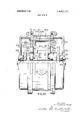
- FIG. 1 is an end view of one form of the engine partly in section to reveal construction
- FIGS. 2 and 3 are part axial plane sections taken on the lines IIII and III-III respectively of FIG. 1,
- FIGS. 4 to 8 are diagrams each showing a different arrangement of piston and follower rollers
- FIG. 9 is an end view of a developed form of the engine partly in section to reveal construction
- FIGS. 10 and 11 are part axial plane sections taken on the lines X-X and XI-XI respectively of FIG. 9 and FIGS. 12 and 13 are detail sectional views each showing a variation in the arrangement of piston roller support.
- the engine chamber 2 is provided by a drum 1 having an inner peripheral wall In ofapproximately elliptical form which four pistons 13, 15 having rectangular crowns follow with oscillatory motion as the engine output shaft 6 rotates.
- Two of the pistons 13 (hereafter referred to as the master pistons and of which one is visible in FIG. 1) are each provided with transverse peripheral seals 13a for sealing contact with the wall la whilst the other two pistons 15 (hereafter referred to as slave pistons) have knuckle seal engagement at 15a with corresponding ends of the master pistons 13 for relative pivotal movement in a substantially gastight manner as the pistons 13,15 follow the elliptical form of the wall la.
- both the latter and the slave pistons 15 are provided with side seals 13b,l5b cooperating with the sidewalls 3 of the engine chamber 2 (FIGS. 2 and 3).
- Each master piston 13 is connected to a pair of link beams 11 (hereafter referred to as master beams 11) one at each side of the piston 13 outside the engine chamber 2.
- the beams 11 being shown united in H-formation by a bolt 11b passing trans versely through the piston 13, stub shafts 11a of the beams 11 having a splined engagement with the piston 13 so as to be rotationally fast therewith whereby the master piston 13 and beams are able to perform oscillatory movement together as a single unit as the piston 13 follows the generally elliptical path provided by the chamber wall 1a.
- each slave piston 15 is connected by a transverse bolt 14b therethrough to corresponding slave link beams 14, stub shafts 14a of the latter having a splined engagement with the slave piston 15 for oscillatory movement of the beams 14 therewith, whilst the master and slave beams 11,14 are pivotally connected at their end portions about the axes of the support rollers 16 carried by the beam assemblies.
- the beam assemblies 11,14 have parallelogrammic movement in a similar manner to the pistons 13,15 as the rollers 16 follow the cam tracks 17 so that such roller support is transmitted by the beam assemblies 11,14 to the pistons 13,15.
- the master beams 11 are also shown pivotally connected by wrist pins 10 at their mid points to radial crank arms 9 rotationally fast with the engine shaft 6 in order to effect drive transmission to the latter on the above-mentioned movement of the pistons 13,15.
- the stub shafts 11a,14a and piston bosses 13d,15d pass through a central opening 12 in each chamber sidewall 3 to the link beams 11,14, the openings 12 being such as to permit necessary movement of the stub shafts l1a,l4a with the pistons 13,15 yet at the same time avoid any interruption of the side sealing contact at 13b,l5b of the pistons 13,15 with the sidewalls 3.
- inlet and exhaust ports 18,19 have been shown in the wall 1a of the drum 1 they may be situated in the sidewalls 3,3 and of suitable extent for appropriate timing of opening and closing of the ports.
- the four piston arrangement herein described and shown in the drawings is particularly suitable for operation by a fuel/air mixture such as petrol/air where the latter is admitted at the inlet 18 from a carburettor since any leakage at the peripheral seals 13a passes from one variable volume between a piston 13 or 15 and the chamber wall In to the next, so that leakage losses are kept to a minimum and likewise the undesired occurrence of an explosive mixture in the central part of the chamber 2 within the pistons 13,15.
- a fuel/air mixture such as petrol/air
- more than one sparking plug may be provided at 20.
- the engine is arranged to operate on the diesel or similar cycle with fuel injection so that only air is drawn in at the inlet 18 only two pistons (viz: the master pistons 13) need be employed or an arrangement of three pistons with'appropriate beam connections to the roller support 16.
- roller and cam track support 16,17 can be of a substantial nature and arranged for adequate lubrication.
- the chamber wall 1a is concave throughout its elliptical profile without any reentrant formation so that spring loading of the peripheral seals 13a need not be provided in the interests of more uniform seal pressure and longer serviceable life of the seals.
- the axes of the support rollers 16 can be substantially coincident with the axes of the peripheral seals 13a whereby the latter follow the required locus or elliptical path in tangential contact with the chamber wall 1a without scuffing and remain theoretically at rest in relation to their pistons 13.
- the axes of the wrist pins 10 i.e., the pivotal connections of the master beam 11 to corresponding crank arms 9) can be advantageously situated on the median between the peripheral seals 13a of the corresponding master pistons 13.
- Refinements may include provision for eccentric setting of the rollers 16 and/or wrist pins 10 for adjustment or preloading purposes while to avoid cantilever stresses the rollers 16 can be arranged in line with the beams 11,14 such as by accommodation in forked ends of the master beams 11 or the use of twin rollers one at each side of the beam ends.
- slave pistons is dispensed with and two (or if desired three) independent pistons 113 (FIG. 9) are employed with only one pair of follower or support rollers 116 to each piston 113 and preferably in a leading position in relation to the latter. Furthermore the center of mass or gravity G ofthe piston assembly is shifted from a position of symmetry in such a manner that the single pair of support rollers 116 are maintained in continuous contact with their cam tracks 117 by the action of centrifugal force on the piston assembly.
- FIG. 4 firstly shows for convenient reference the arrangement of a master piston 13 of the engine shown in FIGS. 1 to 3 in which each of the two pairs of follower rollers 16 have their axis coincident with that of the corresponding peripheral seal 13a.
- the center of gravity G of the piston assembly is symmetrically disposed i.e., on a median passing through the axis of the wrist pin 10 and that of the stub shafts 1 1a.
- each piston 13g With only a pair of follower rollers, the latter need no longer be concentric with a peripheral seal 13a and may be positioned at 1611 (FIG. 6) which arrangement results in a reduced extent of cooperating cam track 17 and also a reduced speed of rotation of the rollers under running conditions.
- the single pair of follower rollers 316 are also concentric with the beam cross shaft 311a but in a trailing position in relation to the median through the axes of the wrist pin 310 and engine shaft 306 so that the center of gravity G is disposed well forwardly in relation to the rollers 316 and cross shaft 311a.
- the action of centrifugal force on the piston assembly is such as to maintain the rollers 316 in contact with a cam track of external form i.e., in the manner shown in FIG. 13 and hereafter described.
- each piston 113 has an angular velocity at or near a maximum value.
- the load on the rollers may tend towards zero when the wrist pins 110 are in the second and fourth quadrants due to the angular deceleration of each piston 113.
- the profile of the inner peripheral wall 1010 of the drum 101 and likewise of the cam track 117 or pitch curve of the latter is of asymmetric form on a mathmatical basis in which the first and third quadrants are similar but differ slightly fromv the second and fourth quadrants which latter are similar to one another.
- Each piston 113 is provided with leading and trailing transverse peripheral seals 113a and also with side seals 113b cooperating with the sidewalls 103 ofthe engine chamber 102.
- each piston 113 may be achieved by adding counterpoise masses to the pistons 113 and/or to the links 111
- the addition of such masses to members subject to cyclic accelerations is undesirable and as described is preferably effected by suitable arrangement of the piston webbing 113d in conjunction with the forward disposition of the single pair of rollers 116 so that the weight of the piston assembly may be kept to a minimum.
- FIG. 13 For the purpose of providing external cam track support for a piston and roller arrangement as per FIG. 8, the arrangement of FIG. 13 can be followed in which a support or follower roller 316 at the end of the cross shaft 311a cooperates with an external cam track 317 provided by the end cover 305, each crank arm or disc 309 being again slotted at 309a for passage of the end portions of the pin 311a therethrough and for necessary relative oscillatory movement of the latter.
- a rotary engine of the character described comprising a drum providing an engine chamber having inlet and outlet ports thereto and an inner peripheral wall of approximately elliptical form; sidewall members secured to the drum one at each side of the chamber; each sidewall member having a central opening; an engine shaft substantially coaxially disposed in said chamber and extending through the central openings in the sidewall members and externally supported for rotation relative to said drum; pistons arranged to follow with oscillatory movement a path of the said approximate elliptical form in leading and trailing transverse sealing contact with the inner peripheral wall of said chamber and in side sealing contact with the side wall members, external link members rotationally fast with corresponding pistons and connected to the pistons through the central openings in the side wall members; external crank members rotationally fast with and extending radially from the engine shaft and pivotally connected to the link members; cam track means fast with the drum and externally disposed in relation to the drum adjacent each side wall member and of corresponding approximate elliptical form to the inner peripheral wall of said chamber and coaxial therewith; and
- a rotary engine according to claim 1 wherein the approximate elliptical form of the inner peripheral wall of the engine chamber and of the cam track means is asymmetric with a view to effecting reduction of the deceleration of angular movement of each piston during the oscillatory motion of the latter whereby the tendency of the follower members to leave contact with the cam track means is minimized.
- a rotary engine according to claim 1 wherein the pistons are pivotally interengaged at their leading and trailing edges with further slave pistons which have a similar oscillatory motion and follow the same path of approximate elliptical form in sealing contact with the inner peripheral wall of the engine chamber.
Abstract
A rotary engine such as an internal combustion engine or pump or compressor is disclosed in which pistons pivotally interlinked with crank members of the engine shaft are arranged to follow with oscillatory movement a path of approximately elliptical form in leading and trailing transverse sealing contact with an inner peripheral wall of the engine chamber of corresponding profile wherein the pistons are externally interconnected through openings in sidewall members of the engine chamber with follower members such as rollers cooperating with cam track means outside the engine chamber, the formation of the cam track means being of corresponding approximate elliptical form to that of the inner peripheral wall of the engine chamber whereby the pistons are supported during their travelling and oscillatory movement in the engine chamber especially for the purpose of minimizing piston seal wear.
Description
United States Patent 1151 3,642,391
Wilson 1451 Feb. 15, 1972 [54] ROTARY ENGINES 1,995,755 3/1935 Smith ..4l8/260 [72] Inventor: Gordon Shirley Wilson, Coventry, England 3295505 1/1967 Jordan 3,369,529 2/1968 Jordan ..4l8/270X [73] Assignee: Corporation of The City of Coventry,
Coventry, England Primary Examiner-Carlton R. Croyle Assistant Examiner-John J. Vrablik [22] Filed 161969 Attorney-Watson, Cole, Grindle&Watson [2]] App|.N0.: 885,481
[57] ABSTRACT [30] Foreign Application Priority Data A rotary engine such as an internal combustion engine or pump or compressor is disclosed in which pistons pivotally in- Dec. 18, Great Britain terlinked crank members ofthe engine Shafi are arranged to follow with oscillatory movement a path of approximately 2% elliptical form in leading and trailing transverse sealing con- E i c 4187260 6 264 tact with an inner peripheral wall of the engine chamber of corresponding profile wherein the pistons are externally interconnected through openings in sidewall members of the engine chamber with follower members such as rollers cooperat- [56] References Cited ing with cam track means outside the engine chamber, the for- UNITED STATES PATENTS mation of the cam track means being of corresponding ap- 1 proximate elliptical form to that of the inner peripheral wall of l the engine chamber whereby the pistons are upported during 147,623 2/1874 Ellis 335,121 2/1886 Forsythe.... 716,970 12/1902 Werner their travelling and oscillatory movement in the engine chamber especially for the purpose of minimizing piston seal Wear. 941,567 11/1909 Fleming ..4l8/264 x 1,715,490 6/1929 Ballerstedt ..4l8/263 x 9 Claims, 13 Drawing Figures PATENTEUFEB 15 m2 3.642.391 SHEET 1 [IF 8 GORDON Smzuzv M/HnSO I ATTo auav PATENTEDFEB 15 I912 3.642.391
SHEET 3 0F 8 INVENTOIZ GORDON SweLEY WILSON ATTQQN EY PATENIEBFEB 15 I972 3.642.391
snmsma INVENTOE GolzDoN SmeuzvWxu-sou M427 flaw/z, @579 ATTORNEY ROTARY ENGINES This invention relates to rotary engines of the kind in which pistons pivotally connected to the engine shaft are arranged to follow with oscillatory movement a path of elliptical or like form in sealing contact with a wall of the engine chamber of corresponding profile.
The object of this invention is to provide an improved engine of this kind primarily as an internal combustion engine but also capable of practical embodiments as a pump or compressor whereby piston seal wear is considerably reduced and other practical advantages achieved as will be apparent from the following disclosure.
In practical embodiments of the invention as applied to a rotary internal combustion engine, the construction and arrangement is as follows, reference being had to the accompanying drawings in which:
FIG. 1 is an end view of one form of the engine partly in section to reveal construction,
FIGS. 2 and 3 are part axial plane sections taken on the lines IIII and III-III respectively of FIG. 1,
FIGS. 4 to 8 are diagrams each showing a different arrangement of piston and follower rollers,
FIG. 9 is an end view of a developed form of the engine partly in section to reveal construction,
FIGS. 10 and 11 are part axial plane sections taken on the lines X-X and XI-XI respectively of FIG. 9 and FIGS. 12 and 13 are detail sectional views each showing a variation in the arrangement of piston roller support.
Like parts are referred to by the same or similar reference numerals throughout the drawings.
For the purposes of description only e.g., in relation to an engine cycle travelling movement of the engine pistons is to be regarded as in a clockwise direction.
Referring firstly to FIGS. 1 to 3, the engine chamber 2 is provided by a drum 1 having an inner peripheral wall In ofapproximately elliptical form which four pistons 13, 15 having rectangular crowns follow with oscillatory motion as the engine output shaft 6 rotates. Two of the pistons 13 (hereafter referred to as the master pistons and of which one is visible in FIG. 1) are each provided with transverse peripheral seals 13a for sealing contact with the wall la whilst the other two pistons 15 (hereafter referred to as slave pistons) have knuckle seal engagement at 15a with corresponding ends of the master pistons 13 for relative pivotal movement in a substantially gastight manner as the pistons 13,15 follow the elliptical form of the wall la.
As hereafter described the pistons 13,15 are supported for such oscillatory or rocking movement in relation to the wall by follower or support members or rollers 16 outside the chamber 2, which rollers 16 follow cam tracks 17 of corresponding approximate elliptical form to that of the chamber wall 111. The peripheral seals 13a of the master pistons 13 are thus only required to perform their sealing function between the pistons 13 and wall 1a and are not subject to inertia forces of the oscillating pistons which forces are borne by the roller support 16. Whereas it is preferable to employ follower rollers at 16 other follower members such as slippers may be used.
The sidewalls 3,3 to the chamber 2 are shown provided by side members 23 bolted to the drum 1 which side members 23 each carry a corresponding cam 17 which is shown integral with its side member 23 but may be in the form ofa hardened insert or the like, e.g., for replacement purposes. The side members 23 also provide support for side covers 5 bolted or similarly secured thereto which covers 5 carry bearings 8 and seals 7 for the engine shaft 6.
In addition to the peripheral seals 13a of the master pistons 13, both the latter and the slave pistons 15 are provided with side seals 13b,l5b cooperating with the sidewalls 3 of the engine chamber 2 (FIGS. 2 and 3).
A fuel inlet port 18 e.g., for a petrol air mixture from a carburettor) to the chamber 2 is shown together with an exhaust port 19 whilst an opening 20 for a sparking plug is also provided unless compression ignition is employed. The master piston 13 shown in FIG. 1 is at the top dead center (T.D.C.) position for a power stroke or movement whilst the slave pistons 15 are at bottom dead center (B.D.C.) positions for compression and exhaust strokes or movements of a four stroke cycle (i.e., at the left and right respectively of FIG. 1).
In the example shown the interlinking of the pistons 13,15 to the support rollers 16 and their driving connection with the engine shaft 6 is as follows:
Each master piston 13 is connected to a pair of link beams 11 (hereafter referred to as master beams 11) one at each side of the piston 13 outside the engine chamber 2. the beams 11 being shown united in H-formation by a bolt 11b passing trans versely through the piston 13, stub shafts 11a of the beams 11 having a splined engagement with the piston 13 so as to be rotationally fast therewith whereby the master piston 13 and beams are able to perform oscillatory movement together as a single unit as the piston 13 follows the generally elliptical path provided by the chamber wall 1a. In a similar manner each slave piston 15 is connected by a transverse bolt 14b therethrough to corresponding slave link beams 14, stub shafts 14a of the latter having a splined engagement with the slave piston 15 for oscillatory movement of the beams 14 therewith, whilst the master and slave beams 11,14 are pivotally connected at their end portions about the axes of the support rollers 16 carried by the beam assemblies. Thus the beam assemblies 11,14 have parallelogrammic movement in a similar manner to the pistons 13,15 as the rollers 16 follow the cam tracks 17 so that such roller support is transmitted by the beam assemblies 11,14 to the pistons 13,15.
The master beams 11 are also shown pivotally connected by wrist pins 10 at their mid points to radial crank arms 9 rotationally fast with the engine shaft 6 in order to effect drive transmission to the latter on the above-mentioned movement of the pistons 13,15.
The stub shafts 11a,14a and piston bosses 13d,15d pass through a central opening 12 in each chamber sidewall 3 to the link beams 11,14, the openings 12 being such as to permit necessary movement of the stub shafts l1a,l4a with the pistons 13,15 yet at the same time avoid any interruption of the side sealing contact at 13b,l5b of the pistons 13,15 with the sidewalls 3.
On each piston 13,15 performing a compression stroke or movement the charge of fuel/air mixture drawn in at 18 by the previous induction movement is directed towards the center of a diminishing volume between the piston 13 or 15 and chamber wall such that the charge is directed with a high degree of turbulence towards the center of the piston 13 or 15 where a pocket or compression chamber 13c or 15c is provided for receiving the charge in readiness for ignition at or about the tope dead center position. Further in this connec tion crowns of the pistons 13,15 are also shown of a convex curvature whereby they closely follow the curvature of the chamber wall la at the top dead center position in obtaining a high degree of compression.
Whereas the inlet and exhaust ports 18,19 have been shown in the wall 1a of the drum 1 they may be situated in the sidewalls 3,3 and of suitable extent for appropriate timing of opening and closing of the ports.
The four piston arrangement herein described and shown in the drawings is particularly suitable for operation by a fuel/air mixture such as petrol/air where the latter is admitted at the inlet 18 from a carburettor since any leakage at the peripheral seals 13a passes from one variable volume between a piston 13 or 15 and the chamber wall In to the next, so that leakage losses are kept to a minimum and likewise the undesired occurrence of an explosive mixture in the central part of the chamber 2 within the pistons 13,15. In such an arrangement where spark ignition is normally employed more than one sparking plug may be provided at 20.
However where the engine is arranged to operate on the diesel or similar cycle with fuel injection so that only air is drawn in at the inlet 18 only two pistons (viz: the master pistons 13) need be employed or an arrangement of three pistons with'appropriate beam connections to the roller support 16.
The drum 1 is shown jacketed at 112 for receiving coolant fluid such as water and/or it may be externally finned for air cooling.
In addition to the simple and robust construction of the engine which is possible, the roller and cam track support 16,17 can be of a substantial nature and arranged for adequate lubrication.
Further practical advantages beyond those already referred to reside in the fact that the chamber wall 1a is concave throughout its elliptical profile without any reentrant formation so that spring loading of the peripheral seals 13a need not be provided in the interests of more uniform seal pressure and longer serviceable life of the seals. The axes of the support rollers 16 can be substantially coincident with the axes of the peripheral seals 13a whereby the latter follow the required locus or elliptical path in tangential contact with the chamber wall 1a without scuffing and remain theoretically at rest in relation to their pistons 13.
Furthermore from kinematic considerations and as shown in FIG. 1 the axes of the wrist pins 10 (i.e., the pivotal connections of the master beam 11 to corresponding crank arms 9) can be advantageously situated on the median between the peripheral seals 13a of the corresponding master pistons 13.
Refinements may include provision for eccentric setting of the rollers 16 and/or wrist pins 10 for adjustment or preloading purposes while to avoid cantilever stresses the rollers 16 can be arranged in line with the beams 11,14 such as by accommodation in forked ends of the master beams 11 or the use of twin rollers one at each side of the beam ends.
With a view to simplification of the construction of the engine and also affording greater latitude as regards manufacturing tolerances as well as accommodating the effects of variations in running loads, speeds, temperatures and wear, a development of the invention is hereafter described more particularly with reference to FIGS. 9 to 11 of the drawings.
In such development the use of slave pistons is dispensed with and two (or if desired three) independent pistons 113 (FIG. 9) are employed with only one pair of follower or support rollers 116 to each piston 113 and preferably in a leading position in relation to the latter. Furthermore the center of mass or gravity G ofthe piston assembly is shifted from a position of symmetry in such a manner that the single pair of support rollers 116 are maintained in continuous contact with their cam tracks 117 by the action of centrifugal force on the piston assembly.
As before the transverse peripheral seals 113a of each piston 113 are relieved from transmitting inertial loads while undesired constraint of each piston is avoided.
Referring to the diagrams shown in FIGS. 4 to 8, FIG. 4 firstly shows for convenient reference the arrangement of a master piston 13 of the engine shown in FIGS. 1 to 3 in which each of the two pairs of follower rollers 16 have their axis coincident with that of the corresponding peripheral seal 13a. In such arrangement the center of gravity G of the piston assembly is symmetrically disposed i.e., on a median passing through the axis of the wrist pin 10 and that of the stub shafts 1 1a.
In one form of the developed arrangement shown in FIG. the trailing pair of support rollers 16 has been omitted and the center of gravity G has'been moved from a position of symmetry to a point lying along a median passing through the wrist pin axis and that of the leading seal 13a and also of the retained leading follower rollers 16. A suitable or optimum position of the center of gravity G is approximately one third of the distance from the axis of the wrist pin 10 towards that of the leading seal 13a while the result of such positioning of the center of gravity G is such that the action of centrifugal force on the piston 13g is to maintain the single pair of leading rollers 16 in constant contact with their cam tracks 17 which action is further assisted by the drag forces at the peripheral seals 13a which exert an anticlockwise turning moment about the wrist pin axis 10. Thus by maintaining roller and cam track contact in this way required positioning of the piston 13g in relation to the drum wall la is maintained and also appropriate contact of the seals 13a therewith.
By providing each piston 13g with only a pair of follower rollers, the latter need no longer be concentric with a peripheral seal 13a and may be positioned at 1611 (FIG. 6) which arrangement results in a reduced extent of cooperating cam track 17 and also a reduced speed of rotation of the rollers under running conditions.
In a still further development in this respect shown in FIG. 7 and which is incorporated in the engine described with reference to FIGS. 9 to 11, the single pair of rollers 116 is mounted concentrically with the axis of the link cross shaft 111a and which achieves a further reduction in the mass of the piston assembly.
In a still further development shown in FIG. 8 the single pair of follower rollers 316 are also concentric with the beam cross shaft 311a but in a trailing position in relation to the median through the axes of the wrist pin 310 and engine shaft 306 so that the center of gravity G is disposed well forwardly in relation to the rollers 316 and cross shaft 311a. In such a case the action of centrifugal force on the piston assembly is such as to maintain the rollers 316 in contact with a cam track of external form i.e., in the manner shown in FIG. 13 and hereafter described.
Referring to FIG. 9 a further consideration which requires to be taken into account is the variation in angular velocity of each piston 113 as the latter follows the inner peripheral wall 101a of the drum 101. Thus when the wrist pins 110 of the radial or crank members 109 from the engine shaft 106 are at 0 and 180 in relation to clockwise movement of the pistons in FIG. 9 (and similarly in FIG. 1) the angular velocity of each piston 113 is at or near a minimum value whilst when the wrist pins 110 of the crank members 109 are at and 270 the pistons 113 have an angular velocity at or near a maximum value. Accordingly where the wrist pins 110 lie between 0 and 90 and also between and 270 (i.e., in the first and third quadrants) the pistons 113 are subject to an angular acceleration whilst when the wrist pins 110 are in the second and fourth quadrants the pistons 113 are subject to angular deceleration.
In the preferred arrangement shown in FIG. 9 where a single pair of rollers 116 are in a leading position in relation to the piston 113 and run within internal cam tracks 117, the load on the rollers may tend towards zero when the wrist pins 110 are in the second and fourth quadrants due to the angular deceleration of each piston 113. With a view to counteracting such effect the profile of the inner peripheral wall 1010 of the drum 101 and likewise of the cam track 117 or pitch curve of the latter is of asymmetric form on a mathmatical basis in which the first and third quadrants are similar but differ slightly fromv the second and fourth quadrants which latter are similar to one another. By such asymmetric profile, reduction of the maximum angular deceleration of each piston 113 in the second and fourth quadrants is obtained at the expense of an increase in the maximum angular acceleration of each piston in the first and third quadrants. The first effect assists in maintaining contact between the rollers 116 and cam tracks 117 when the forces are at a minimum while the second effect is of little consequence. This feature is particularly evident from the form of the cam track 117, shown in FIG. 9.
By maintaining continuous contact of a single pair of preferably leading rollers 116 with cam tracks 117 of asymmetric profile, hammer action of the rollers 116 against the cam tracks 117 is virtually avoided under running conditions. However, and if necessary, to further counteract such action and in particular to avoid roller chatter at low or idling engine speeds, torsion spring loading may be provided between the radial or crank members 109 and links 111 (i.e., at the wrist pins 110) whereby the rollers 116 are urged to continuous contact with the cam tracks 1 17.
Further in the interests of maintaining continuous roller contact with the cam track a minimum radius of gyration of each piston assembly about its center of mass or gravity G is desirable whilst still further in such interests the ratio of the major diameter to the minor diameter of the approximate elliptical profile of the inner peripheral wall 101a of the drum 101 and also of the cam track 117 should be kept to a minimum but without detriment to the breathing capacity and hence power output ofthe engine.
Referring in detail to FIGS. 9 to 11 the engine shown is provided with a pair of oppositely disposed independent pistons 113 one of which is visible in the upper part of the FIGURES, each piston following the inner peripheral wall 101a of the drum 101, which wall 101a is of generally elliptical form in profile i.e., it is asymmetrically formed for the purpose of minimizing angular deceleration of the pistons in the second and fourth quadrants in the manner already referred to.
Each piston 113 is provided with leading and trailing transverse peripheral seals 113a and also with side seals 113b cooperating with the sidewalls 103 ofthe engine chamber 102.
Each piston 113 is provided with a single pair of support or follower rollers 116 which are arranged in a leading position in relation to the piston 113 and each cooperate with a corresponding cam track 117 of corresponding asymmetric profile to that of the inner peripheral wall 101a. Each cam track is provided by a sideplate 127 which, together with an adjacent sideplate 123 of the combustion chamber 102 provides spaces 121 for coolant such as water alongside the combustion chamber 102, which spaces are communicated with the coolantjacket 101b via openings 101C for suitable coolant flow. The cam track plates 127 also provide support for side covers 105 bolted or similarly secured thereto which covers 105 carry bearings 108 and seals 107 for the engine shaft 106.
In the manner already indicated in FIG. 7 the axis of the single pair of rollers 116 is coincident with a cross member or shaft 111a through the piston 113 and carrying links 111 at each end which links 111 are pivotally connected by wrist pins 110 to the radial or crank members 109 extending from and rotationally fast with the engine output shaft 106. The radial members 109 consist of arms or, as shown may take the form of discs. while the cross shaft 1110 is rotationally fast with the piston 113 and with the links 111 by splined engagement therewith which should be of adequate strength to withstand the turning moment ofexplosion forces acting on the crown of the piston 113. In addition the cross shaft 111a directly carries the pair of rollers 116 such as by needle bearings support 126 thereon whereby the rollers cooperate with corresponding cam tracks 117.
As before the travelling and oscillatory movement of the pistons 113 in sealing contact against the inner peripheral wall 101a effect, by the varying volume between them and the wall, induction, compression, power and exhaust strokes or movements in relation to the inlet and exhaust ports 118 and 119 respectively and in relation to any sparking plug provided at 120.
The webbing 113d of the piston 113 and the forward disposition of the cross shaft 111a and rollers 116 carried thereby is such that the center of mass or gravity G of the piston assembly is forwardly disposed so that the action of centrifugal force thereon causes the rollers 116 to be maintained in continuous contact with their cam tracks 117.
Whereas the required shifting or displacement of the center of gravity of each piston 113 may be achieved by adding counterpoise masses to the pistons 113 and/or to the links 111, the addition ofsuch masses to members subject to cyclic accelerations is undesirable and as described is preferably effected by suitable arrangement of the piston webbing 113d in conjunction with the forward disposition of the single pair of rollers 116 so that the weight of the piston assembly may be kept to a minimum.
As shown in FIGS. 10 or 11 lubrication of the various bearings is provided by oilways 106a, 109a, 110a, lllb respectively in the engine shaft 106, crank discs 109, wrist pins and links 111 for communication with a longitudinal bore 111! in the tubular cross shaft 111a whereby oil flow is able to take place via the various passages and bearings from one end to the other of the engine shaft 106 in effecting a type of dry sump lubrication. Radial ducts 111d in the pin 111a pass lubricant to the needle bearings 126 of the rollers 116.
Although such lubrication should be adequate, it is subject to a temperature gradient under running conditions and in a refinement a duplicated arrangement of oilways may pass oil in an opposite direction via twin bores along the cross shaft 1110 or along a longitudinally partitioned single or axial bore in the latter.
In order to minimize the entry of oil into the combustion chamber 102 openings 123a in the side members 123 are largely closed by flanged discs 130 fast with the engine shaft 106 which discs are appropriately slotted as at 130a for passage therethrough of the end portions of each cross shaft 111a and to allow for relative oscillatory movement of the latter. Further in this respect each shaft 111a carries adjacent each roller 116 thereon an oil flinger ring 131 whereby entry of lubricant through the slots 130a is kept to a minimum, while oil drainage holes may be provided in a lower part of the side plates 127 opposite the outer periphery of the discs 130.
Referring to FIG. 12 and in a variation of the engine just described, a support or follower roller 216 is carried by each end of the cross shaft 211a rotationally fast with the piston 213, which roller 216 cooperates with a cam track 217 provided on an adjacent side cover 205. For this purpose each crank arm or disc 209 is slotted at 209a for passage of the end portion of the pin 211a therethrough and necessary relative oscillatory movement.
For the purpose of providing external cam track support for a piston and roller arrangement as per FIG. 8, the arrangement of FIG. 13 can be followed in which a support or follower roller 316 at the end of the cross shaft 311a cooperates with an external cam track 317 provided by the end cover 305, each crank arm or disc 309 being again slotted at 309a for passage of the end portions of the pin 311a therethrough and for necessary relative oscillatory movement of the latter.
By closing or omitting the sparking plug opening 20 or 120 in any of the embodiments of the engine herein describe, the engine can, of course, be used as a gaseous fluid pump or compressor by driving the shaft 6 or 106 while multiple arrangements of the engine are possible whether as a prime mover or pump.
We claim:
1. A rotary engine of the character described comprising a drum providing an engine chamber having inlet and outlet ports thereto and an inner peripheral wall of approximately elliptical form; sidewall members secured to the drum one at each side of the chamber; each sidewall member having a central opening; an engine shaft substantially coaxially disposed in said chamber and extending through the central openings in the sidewall members and externally supported for rotation relative to said drum; pistons arranged to follow with oscillatory movement a path of the said approximate elliptical form in leading and trailing transverse sealing contact with the inner peripheral wall of said chamber and in side sealing contact with the side wall members, external link members rotationally fast with corresponding pistons and connected to the pistons through the central openings in the side wall members; external crank members rotationally fast with and extending radially from the engine shaft and pivotally connected to the link members; cam track means fast with the drum and externally disposed in relation to the drum adjacent each side wall member and of corresponding approximate elliptical form to the inner peripheral wall of said chamber and coaxial therewith; and follower members interconnected with the pistons and cooperating with the cam track means for providing support to the pistons during their travelling and oscillatory movement in the engine chamber.
2. A rotary engine according to claim 1 wherein the follower members are disposed at at least a leading position in relation to a piston interconnected therewith i.e., in regard to the direction of travelling movement of the pistons along their path of approximately elliptical form in the engine chamber,
3. A rotary engine according to claim 1 wherein the follower members are substantially coaxial with connection of their associated piston to corresponding external link members. I
4. A rotary engine according to claim 1 wherein the axis of pivotal connection of the external link members from each piston to the engine shaft crank members lies substantially on the median between the leading and trailing transverse sealing contact of the piston with the inner peripheral wall of the engine chamber,
5. A rotary engine according to claim 1 wherein the center of mass of each piston is offset in a forward direction in relation to pivotal connection of corresponding external link members to the engine shaft crank members i.e., in regard to the direction of travelling movement of the piston along its path of approximate elliptical form in the engine chamber, whereby the action of centrifugal force on each piston during running conditions serves to maintain the follower members interconnected with the pistons substantially in continuous contact with the cam track means.
6. A rotary engine according to claim 1 wherein the approximate elliptical form of the inner peripheral wall of the engine chamber and of the cam track means is asymmetric with a view to effecting reduction of the deceleration of angular movement of each piston during the oscillatory motion of the latter whereby the tendency of the follower members to leave contact with the cam track means is minimized.
7. A rotary engine according to claim 1 wherein the pistons are pivotally interengaged at their leading and trailing edges with further slave pistons which have a similar oscillatory motion and follow the same path of approximate elliptical form in sealing contact with the inner peripheral wall of the engine chamber.
8. A rotary engine according to claim 1 wherein the follower members are carried by the external link members.
9. A rotary engine according to claim 8 wherein the external link members consist of pairs of beams rotationally fast with corresponding pistons and pivotally connected at their midpoints with corresponding engine shaft crank members, the beams carrying the follower members at their ends.
nun
Claims (9)
1. A rotary engine of the character described comprising a drum providing an engine chamber having inlet and outlet ports thereto and an inner peripheral wall of approximately elliptical form; sidewall members secured to the drum one at each side of the chamber; each sidewall member having a central opening; an engine shaft substantially coaxially disposed in said chamber and extending through the central openings in the sidewall members and externally supported for rotation relative to said drum; pistons arranged to follow with oscillatory movement a path of the said approximate elliptical form in leading and trailing transverse sealing contact with the inner peripheral wall of said chamber and in side sealing contact with the side wall members, external link members rotationally fast with corresponding pistons and connected to the pistons through the central openings in the side wall members; external crank members rotationally fast with and extending radially from the engine shaft and pivotally connected to the link members; cam track means fast with the drum and externally disposed in relation to the drum adjacent each side wall member and of corresponding approximate elliptical form to the inner peripheral wall of said chamber and coaxial therewith; and follower members interconnected with the pistons and cooperating with the cam track means for providing support to the pistons during their travelling and oscillatory movement in the engine chamber.
2. A rotary engine according to claim 1 wherein the follower members are disposed at at least a leading position in relation to a piston interconnected therewith i.e., in regard to the direction of travelling movement of the pistons along their path of approximately elliptical form in the engine chamber,
3. A rotary engine according to claim 1 wherein the follower members are substantially coaxial with connection of their associated piston to corresponding external link members.
4. A rotary engine according to claim 1 wherein the axis of pivotal connection of the external link members from each piston to the engine shaft crank members lies substantially on the median between the leading and trailing transverse sealing contact of the piston with the inner peripheral wall of the engine chamber,
5. A rotary engIne according to claim 1 wherein the center of mass of each piston is offset in a forward direction in relation to pivotal connection of corresponding external link members to the engine shaft crank members i.e., in regard to the direction of travelling movement of the piston along its path of approximate elliptical form in the engine chamber, whereby the action of centrifugal force on each piston during running conditions serves to maintain the follower members interconnected with the pistons substantially in continuous contact with the cam track means.
6. A rotary engine according to claim 1 wherein the approximate elliptical form of the inner peripheral wall of the engine chamber and of the cam track means is asymmetric with a view to effecting reduction of the deceleration of angular movement of each piston during the oscillatory motion of the latter whereby the tendency of the follower members to leave contact with the cam track means is minimized.
7. A rotary engine according to claim 1 wherein the pistons are pivotally interengaged at their leading and trailing edges with further slave pistons which have a similar oscillatory motion and follow the same path of approximate elliptical form in sealing contact with the inner peripheral wall of the engine chamber.
8. A rotary engine according to claim 1 wherein the follower members are carried by the external link members.
9. A rotary engine according to claim 8 wherein the external link members consist of pairs of beams rotationally fast with corresponding pistons and pivotally connected at their midpoints with corresponding engine shaft crank members, the beams carrying the follower members at their ends.
Applications Claiming Priority (1)
| Application Number | Priority Date | Filing Date | Title |
|---|---|---|---|
| GB6024968 | 1968-12-18 |
Publications (1)
| Publication Number | Publication Date |
|---|---|
| US3642391A true US3642391A (en) | 1972-02-15 |
Family
ID=10485300
Family Applications (1)
| Application Number | Title | Priority Date | Filing Date |
|---|---|---|---|
| US885481A Expired - Lifetime US3642391A (en) | 1968-12-18 | 1969-12-16 | Rotary engines |
Country Status (2)
| Country | Link |
|---|---|
| US (1) | US3642391A (en) |
| GB (1) | GB1289479A (en) |
Cited By (9)
| Publication number | Priority date | Publication date | Assignee | Title |
|---|---|---|---|---|
| FR2235268A1 (en) * | 1973-06-27 | 1975-01-24 | Martin Artajo Jose | |
| US3918415A (en) * | 1972-09-19 | 1975-11-11 | Ishida Industry Company Limite | Rotary internal combustion engine |
| WO1985001777A2 (en) * | 1983-10-13 | 1985-04-25 | Hubert Petutschnig | Rotary motor, rotary compressor |
| DE19901110A1 (en) * | 1999-01-14 | 2000-07-27 | Herbert Huettlin | Swing piston machine |
| US6315538B1 (en) * | 2000-05-26 | 2001-11-13 | Masahiro Tagami | Driven equipment for fluid machinery |
| US6494697B2 (en) * | 2000-05-26 | 2002-12-17 | Masahiro Tagami | Driven equipment for fluid machinery |
| US6718938B2 (en) * | 2000-05-12 | 2004-04-13 | Peter Szorenyi | Hinged rotor internal combustion engine |
| US20050025633A1 (en) * | 2002-12-20 | 2005-02-03 | Hiroshi Ichikawa | Rotating fluid machine |
| US20110280757A1 (en) * | 2008-11-12 | 2011-11-17 | Jean-Pierre Ambert | Rotary machine of the deformable rhombus type comprising an improved transmission mechanism |
Citations (9)
| Publication number | Priority date | Publication date | Assignee | Title |
|---|---|---|---|---|
| US119714A (en) * | 1871-10-10 | Improvement in water-meters | ||
| US147623A (en) * | 1874-02-17 | Improvement in machinery for forcing and exhausting air | ||
| US335121A (en) * | 1886-02-02 | Rotary steam-engine | ||
| US716970A (en) * | 1902-05-26 | 1902-12-30 | Edward H Werner | Rotary engine. |
| US941567A (en) * | 1908-04-30 | 1909-11-30 | Frank Fleming | Rotary combustion-engine. |
| US1715490A (en) * | 1924-05-20 | 1929-06-04 | William D Ballerstedt | Rotary steam engine |
| US1995755A (en) * | 1933-07-17 | 1935-03-26 | George H Smith | Rotary motor |
| US3295505A (en) * | 1963-05-31 | 1967-01-03 | Jordan Alfred | Rotary piston apparatus |
| US3369529A (en) * | 1966-09-29 | 1968-02-20 | Alfred Jordan | Rotary internal combustion engine |
-
1968
- 1968-12-18 GB GB6024968A patent/GB1289479A/en not_active Expired
-
1969
- 1969-12-16 US US885481A patent/US3642391A/en not_active Expired - Lifetime
Patent Citations (9)
| Publication number | Priority date | Publication date | Assignee | Title |
|---|---|---|---|---|
| US119714A (en) * | 1871-10-10 | Improvement in water-meters | ||
| US147623A (en) * | 1874-02-17 | Improvement in machinery for forcing and exhausting air | ||
| US335121A (en) * | 1886-02-02 | Rotary steam-engine | ||
| US716970A (en) * | 1902-05-26 | 1902-12-30 | Edward H Werner | Rotary engine. |
| US941567A (en) * | 1908-04-30 | 1909-11-30 | Frank Fleming | Rotary combustion-engine. |
| US1715490A (en) * | 1924-05-20 | 1929-06-04 | William D Ballerstedt | Rotary steam engine |
| US1995755A (en) * | 1933-07-17 | 1935-03-26 | George H Smith | Rotary motor |
| US3295505A (en) * | 1963-05-31 | 1967-01-03 | Jordan Alfred | Rotary piston apparatus |
| US3369529A (en) * | 1966-09-29 | 1968-02-20 | Alfred Jordan | Rotary internal combustion engine |
Cited By (14)
| Publication number | Priority date | Publication date | Assignee | Title |
|---|---|---|---|---|
| US3918415A (en) * | 1972-09-19 | 1975-11-11 | Ishida Industry Company Limite | Rotary internal combustion engine |
| FR2235268A1 (en) * | 1973-06-27 | 1975-01-24 | Martin Artajo Jose | |
| WO1985001777A2 (en) * | 1983-10-13 | 1985-04-25 | Hubert Petutschnig | Rotary motor, rotary compressor |
| WO1985001777A3 (en) * | 1983-10-13 | 1985-06-06 | Hubert Petutschnig | Rotary motor, rotary compressor |
| EP0158765A1 (en) * | 1983-10-13 | 1985-10-23 | Hubert Petutschnig | Rotary engine, rotary compressor |
| DE19901110A1 (en) * | 1999-01-14 | 2000-07-27 | Herbert Huettlin | Swing piston machine |
| DE19901110C2 (en) * | 1999-01-14 | 2002-06-06 | Herbert Huettlin | Oscillating piston engine |
| US6431139B1 (en) | 1999-01-14 | 2002-08-13 | Huettlin Herbert | Oscillating-piston engine |
| US6718938B2 (en) * | 2000-05-12 | 2004-04-13 | Peter Szorenyi | Hinged rotor internal combustion engine |
| US6315538B1 (en) * | 2000-05-26 | 2001-11-13 | Masahiro Tagami | Driven equipment for fluid machinery |
| US6494697B2 (en) * | 2000-05-26 | 2002-12-17 | Masahiro Tagami | Driven equipment for fluid machinery |
| US20050025633A1 (en) * | 2002-12-20 | 2005-02-03 | Hiroshi Ichikawa | Rotating fluid machine |
| US20110280757A1 (en) * | 2008-11-12 | 2011-11-17 | Jean-Pierre Ambert | Rotary machine of the deformable rhombus type comprising an improved transmission mechanism |
| US8951028B2 (en) * | 2008-11-12 | 2015-02-10 | Vincent Genissieux | Rotary machine of the deformable rhombus type comprising an improved transmission mechanism |
Also Published As
| Publication number | Publication date |
|---|---|
| GB1289479A (en) | 1972-09-20 |
Similar Documents
| Publication | Publication Date | Title |
|---|---|---|
| EP0357291B1 (en) | Crankless reciprocating machine | |
| US4004556A (en) | Rotary internal combustion engine of axially sliding vane type | |
| US2511441A (en) | Rotary internal-combustion engine | |
| US4270395A (en) | Motion translating mechanism | |
| US3642391A (en) | Rotary engines | |
| US4173151A (en) | Motion translating mechanism | |
| US3931809A (en) | Rotary internal combustion engine | |
| US4010716A (en) | Rotary engine | |
| WO2016095757A1 (en) | Rotary piston type working machine | |
| EP1300563A2 (en) | An internal combustion engine | |
| US2050603A (en) | Engine | |
| US2124327A (en) | Rotary internal combustion engine | |
| AU672389B2 (en) | Positive displacement machine with reciprocating and rotating pistons, particulary four-stroke engine | |
| US3374776A (en) | Two-stroke internal combustion engine | |
| US4086879A (en) | Rotary engine with revolving and oscillating pistons | |
| US1809577A (en) | Internal combustion engine | |
| US2503894A (en) | Valveless type rotary power unit | |
| US4009690A (en) | Rotary internal combustion engine | |
| US3456623A (en) | Suction system for rotary piston internal combustion engines | |
| US2370934A (en) | Fluid pressure machine | |
| US3229677A (en) | Engines, pumps or the like | |
| CZ290649B6 (en) | Rotary positive displacement apparatus | |
| US3999523A (en) | Internal combustion engine | |
| US10890110B2 (en) | Internal combustion engine with a rotating piston and uni-directional rolling bear | |
| US4036566A (en) | Fluid displacement apparatus |