US3540307A - Tumbling gear planetary transmission - Google Patents
Tumbling gear planetary transmission Download PDFInfo
- Publication number
- US3540307A US3540307A US743994A US3540307DA US3540307A US 3540307 A US3540307 A US 3540307A US 743994 A US743994 A US 743994A US 3540307D A US3540307D A US 3540307DA US 3540307 A US3540307 A US 3540307A
- Authority
- US
- United States
- Prior art keywords
- gear
- motor
- planetary transmission
- tumbling
- shaft
- Prior art date
- Legal status (The legal status is an assumption and is not a legal conclusion. Google has not performed a legal analysis and makes no representation as to the accuracy of the status listed.)
- Expired - Lifetime
Links
- 230000005540 biological transmission Effects 0.000 title description 48
- 238000010276 construction Methods 0.000 description 7
- 230000002441 reversible effect Effects 0.000 description 4
- 230000007246 mechanism Effects 0.000 description 3
- 230000004048 modification Effects 0.000 description 2
- 238000012986 modification Methods 0.000 description 2
- GJAARPKBDFKHFS-UHFFFAOYSA-N Gerin Natural products COC(=O)C(=C)C1CC2C(=C)C(=O)C=CC2(C)CC1OC(=O)C GJAARPKBDFKHFS-UHFFFAOYSA-N 0.000 description 1
- 208000027418 Wounds and injury Diseases 0.000 description 1
- 230000001154 acute effect Effects 0.000 description 1
- 230000006378 damage Effects 0.000 description 1
- 238000012840 feeding operation Methods 0.000 description 1
- 239000012530 fluid Substances 0.000 description 1
- 208000014674 injury Diseases 0.000 description 1
- 230000001105 regulatory effect Effects 0.000 description 1
Images


Classifications
-
- F—MECHANICAL ENGINEERING; LIGHTING; HEATING; WEAPONS; BLASTING
- F16—ENGINEERING ELEMENTS AND UNITS; GENERAL MEASURES FOR PRODUCING AND MAINTAINING EFFECTIVE FUNCTIONING OF MACHINES OR INSTALLATIONS; THERMAL INSULATION IN GENERAL
- F16H—GEARING
- F16H3/00—Toothed gearings for conveying rotary motion with variable gear ratio or for reversing rotary motion
- F16H3/44—Toothed gearings for conveying rotary motion with variable gear ratio or for reversing rotary motion using gears having orbital motion
- F16H3/72—Toothed gearings for conveying rotary motion with variable gear ratio or for reversing rotary motion using gears having orbital motion with a secondary drive, e.g. regulating motor, in order to vary speed continuously
-
- B—PERFORMING OPERATIONS; TRANSPORTING
- B23—MACHINE TOOLS; METAL-WORKING NOT OTHERWISE PROVIDED FOR
- B23Q—DETAILS, COMPONENTS, OR ACCESSORIES FOR MACHINE TOOLS, e.g. ARRANGEMENTS FOR COPYING OR CONTROLLING; MACHINE TOOLS IN GENERAL CHARACTERISED BY THE CONSTRUCTION OF PARTICULAR DETAILS OR COMPONENTS; COMBINATIONS OR ASSOCIATIONS OF METAL-WORKING MACHINES, NOT DIRECTED TO A PARTICULAR RESULT
- B23Q5/00—Driving or feeding mechanisms; Control arrangements therefor
- B23Q5/22—Feeding members carrying tools or work
- B23Q5/34—Feeding other members supporting tools or work, e.g. saddles, tool-slides, through mechanical transmission
- B23Q5/38—Feeding other members supporting tools or work, e.g. saddles, tool-slides, through mechanical transmission feeding continuously
- B23Q5/46—Feeding other members supporting tools or work, e.g. saddles, tool-slides, through mechanical transmission feeding continuously with variable speed ratio
-
- F—MECHANICAL ENGINEERING; LIGHTING; HEATING; WEAPONS; BLASTING
- F16—ENGINEERING ELEMENTS AND UNITS; GENERAL MEASURES FOR PRODUCING AND MAINTAINING EFFECTIVE FUNCTIONING OF MACHINES OR INSTALLATIONS; THERMAL INSULATION IN GENERAL
- F16H—GEARING
- F16H1/00—Toothed gearings for conveying rotary motion
- F16H1/28—Toothed gearings for conveying rotary motion with gears having orbital motion
- F16H1/32—Toothed gearings for conveying rotary motion with gears having orbital motion in which the central axis of the gearing lies inside the periphery of an orbital gear
- F16H1/321—Toothed gearings for conveying rotary motion with gears having orbital motion in which the central axis of the gearing lies inside the periphery of an orbital gear the orbital gear being nutating
-
- F—MECHANICAL ENGINEERING; LIGHTING; HEATING; WEAPONS; BLASTING
- F28—HEAT EXCHANGE IN GENERAL
- F28D—HEAT-EXCHANGE APPARATUS, NOT PROVIDED FOR IN ANOTHER SUBCLASS, IN WHICH THE HEAT-EXCHANGE MEDIA DO NOT COME INTO DIRECT CONTACT
- F28D9/00—Heat-exchange apparatus having stationary plate-like or laminated conduit assemblies for both heat-exchange media, the media being in contact with different sides of a conduit wall
-
- Y—GENERAL TAGGING OF NEW TECHNOLOGICAL DEVELOPMENTS; GENERAL TAGGING OF CROSS-SECTIONAL TECHNOLOGIES SPANNING OVER SEVERAL SECTIONS OF THE IPC; TECHNICAL SUBJECTS COVERED BY FORMER USPC CROSS-REFERENCE ART COLLECTIONS [XRACs] AND DIGESTS
- Y10—TECHNICAL SUBJECTS COVERED BY FORMER USPC
- Y10T—TECHNICAL SUBJECTS COVERED BY FORMER US CLASSIFICATION
- Y10T74/00—Machine element or mechanism
- Y10T74/18—Mechanical movements
- Y10T74/18056—Rotary to or from reciprocating or oscillating
- Y10T74/18296—Cam and slide
- Y10T74/18336—Wabbler type
Definitions
- the transmission has two rotatable coaxial input shafts driven by respective motors and an output shaft, wherein one input shaft is provided with a coaxial ring gear and the other input shaft is provided with a meshing ring gear freely rotatable about on an inclined axis; a driving universal type connection is provided between the output shaft and the inclined ring gear, and the meshing gears have a different number of teeth.
- One of the driving motors is provided with a brake, which acts as an overload friction clutch upon the output shaft being driven from the outside above a predetermined torque.
- the tumbling gear planetary transmission has a motor driven hollow input shaft provided with a coaxial ring bevel gear, a separate coaxial motor driven input shaft provided with a freely rotatable inclined bevel gear meshing with and having a different number of teeth than the first mentioned bevel gear, and an output shaft concentrically mounted within the first mentioned input shaft and provided with a universal joint type driving connection with the inclined gear.
- the transmission has the above-mentioned advantages of a mechanical drive and is characterized by a simple construction which has an extremely simple operation as compared to the heretofore known gear transmission.
- the gear transmission of the present invention may be manufactured very economically so that the disadvantages of the known transmissions relating to initial expense are effectively eliminated.
- the gears are closed within a housing and a motor for driving the hollow input shaft is provided with a friction brake that may operate as an overload friction clutch to prevent injury to the slower fine adjustment mechanism.
- the motors may be provided as a pole changeable electric motor, or an infinitely variable DC. motor provided with a resistance control, or by an in- 3,540,307 Patented Nov. 17, 1970 finitely variable fluid motor, particularly oil, for example.
- connection between the inclined gear and the shaft output may be a meshing pair of gears, a universal joint or a ball-and-socket joint to provide a force locking drive.
- the driving motors may be provided within the housing side by side, or in series, or positioned oppositely with respect to each other.
- An additional saving in the space requirements and a simplification of the transmission may be obtained by providing only a single motor, with a suitable selective drive means for the two shaft inputs, for example a magnetic clutch and/ or drive switching gear.
- a particularly economical and space saving power transmission between the respective motors and input shafts may be provided with a chain or gear drive. It is also contemplated that V-belt drives, resilient chains, or the like, may be employed for this purpose.
- FIG. 1 is a schematic illustration of a tumbling gear planetary transmission according to the present invention with a ball and socket driving connection;
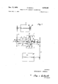
- FIG. 2 is an axial partial cross-sectional view taken through the transmission of the present invention employing a pair of gears as the driving connection;
- FIG. 3 is an axial end view of the planetary transmission according to FIG. 2, viewed in the direction of arrow 3 in FIG. 2;
- FIG. 4 is a schematic end view, similar to the view of FIG. 3, of a different arrangement of the motors, which are shown side by side;
- FIG. 5 is a schematic end view of the housing showing the driving motors in series or tandem;
- FIG. 6 is a schematic axial cross-sectional view through the transmission according to claim 5 showing the motors coaxially disposed in series or tandem;
- FIG. 7 is a schematic illustration of a tumbling gear planetary transmission according to the present invention wherein a magnetic clutch is drivingly connected between a single motor and the corresponding shaft member.
- the tumbling gear planetary transmission has a relatively stationary housing 1 fixedly mounted by means of the flanged base 2, which may be bolted to a suitable support.
- axially spaced roller bearings 3 and 4 rotatably mount the tubular input shaft 5.
- the axially spaced roller bearings 6 and 7 rotatably mount the coaxial input shaft 8 within the housing 1.
- the hollow input shaft 5 may be driven by means of a chain, toothed belt or the like 9, drivingly connected with the rapid traverse electric motor 11.
- the motor 11 is provided with a brake 10 that also serves as an overload friction clutch, which will slip if the transmission is overloaded with the fine or slow traverse gear engaged.
- the flanged base 12 of the rapid traverse motor 11 is suit ably bolted to the outside of the housing 1.
- the motor 11 is infinitely variable in speed and may be reversible with respect to its direction of rotation.
- the input shaft 8 may be driven similarly by a chain or toothed rubber belt 13 driving connected with a slow traverse or fine gear motor 14, which is also preferably infinitely variable in speed and reversible with respect to its direction of rotation.
- the slow traverse motor 14 is provided with a flanged base 15 suitably bolted to the side of the housing 1 so that, as seen in FIG. 3, planes 0A and OB passing respectively through the motor shafts and the common axis of the input shafts will form a right angle.
- the inside end of the input shaft 8 is provided with an annular surface 16 extending obliquely with respect to the axis of rotation of shaft 8, and a similarly inclined collar 17 for supportingly receiving a roller bearing 18 mounting a similarly inclined bevel gear 19.
- An axial thrust bearing 20 is additionally provided between the shaft 8 and the inclined gear 19 to absorb longitudinal thrusts therebetween.
- the inclined bevel gear 19 is freely rotatably mounted on and at an inclination with respect to the input shaft 8.
- the inclined bevel gear 19 is in meshing engagement with the bevel ring gear 21, which gear 21 is rigidly connected to the inside end of the hollow input shaft 5.
- the gears 19 and 21 have the same pitch but a different number of teeth; preferably a difference of one or two teeth between the gears 19 and 21.
- a small bevel gear 22 is rigidly secured, preferably by a threaded connection, to the inside of the inclined bevel gear 19 for meshing engagement with bevel gear 24 that is rigidly mounted on the inside end of the driven output shaft 23 by means of a force-fit.
- Gears 22 and 24 have the same pitch and the same number of teeth to provide a driving connection between the inclined ring gear and the driven output shaft 23.
- the bevel gears 22 and 24 may be replaced by a force driving ball and socket joint or a similarly acting universal joint, as shown in FIG. 1.
- Axially spaced roller bearings 25 and 26 are provided between the hollow input shaft and the output shaft 23 to concentrically rotatably mount the output shaft 23.
- Axial thrust bearings 27 are provided to absorb the longitudinal pressure between the input shaft 5 and the output shaft 23.
- FIG. 4 The modified spatial arrangement schematically illustrated in FIG. 4 is provided with a housing 1 receiving therein the side by side positioned motors 11' and 14.
- FIGS. 5 and 6 illustrate a further modified construction of the housing 1" wherein the motors 11" and 14" may be positioned in series or in tandem. Otherwise, the struc ture of FIGS. 4-6 is identical to the construction previously described in FIGS. 2 and 3.
- one of the motors may be omitted and replaced with a magnetic clutch.
- the magnetic clutch designated generally by numeral 28, is used with only motor 11 and is located on the same side as drive means 9.
- the magnetic clutch 28 is drivingly connected with the motor 11 and the input drive means 13.
- the clutch would be utilized to provide a driving connection between the slow traverse motor 14 and a suitable gear transmission, for driving the two input shafts.
- FIG. 1 Since the schematic construction of FIG. 1 is identical to the specifically illustrated construction of FIG. 2, except for the driving connection between the inclined gear and the output shaft, their operation is identical.
- the planetary transmission When the planetary transmission is used with a machine tool, which is the preferred combination, particularly a lathe, it will first be necessary to bring the tool carriage or work piece carrier rapidly to a processing station, for example.
- the rapid traverse motor 11 is actuated and the slow traverse motor 14 remains idle.
- the motor 11, driving chain, and hollow shaft 5 will thus rotate the bevel ring gear 21.
- the inclined bevel gear 19 will be rotatably driven about its inclined axis through meshing engagement with the gear 21, which rotation of the inclined gear 19 will be transmitted by means of the interengaged bevel gears 22, 24, or alternatively the universal type joint 28 of FIG. 1, to the driven output shaft 23. Therefore, the output shaft 23 will rotate at a high speed to quickly bring the work piece or tool initially to the processing point or station.
- An adjustment of the rapid traverse is obtained by additionally rotating the slow traverse motor 14 in the same direction to increase the speed of the output shaft 23 or rotating the slow traverse motor 14 in the reverse direction to correspondingly retard the speed of the output shaft 23. Also, with the infinite adjustability of each of the motors 11, 14, any desired speed may be obtained within a predetermined relatively wide range of speeds.
- the tool or work carriage may be quickly returned to its starting position by reversing the rapid traverse motor 11.
- a fine or precision advance may be obtained by actuating the slow traverse motor 14 and deactivating the rapid traverse motor 11.
- the motor 14 will drive the input shaft 8 rotatably about its longitudinal axis.
- the inclined bevel gear 19 With ring gear 21 now relatively stationary, the inclined bevel gear 19 will have a tumbling planetary type motion as it tracks about gear 21 during rotation of input shaft 8. Only because the number of teeth differ between the gears 19 and 21, a rotation will be imparted to the driven shaft 23 through the driving connection of the bevel gears 22, 24 or alternatively the universal joint 28 of FIG. 1.
- rotational output of the transmission may be obtained by varying the speed of the respective motors and the direction of rotation of the respective motors for simultaneous operation.
- gear ratio may be further modified with a corresponding modification in the number of teeth between the gears 19 and 21.
- a tumbling gear planetary transmission comprising: a relatively stationary support; first, second, and third shaft members rotatably mounted about the same axis of rotation and with respect to said support; said first shaft member freely carrying a gear with a fixed number of teeth for free relative rotation thereon with respect to an axis inclined with respect to the axis of said first shaft member; said second shaft member drivingly carrying a second gear having a fixed number of teeth different from the fixed number of teeth of said first gear and in meshing engagement with said first gear, wherein said first and second gears define a relatively small acute angle therebetween; said second shaft member and second gear carried thereon being mounted for rotation about an axis inclined with respect to said first gear axis of rotation; said second shaft member being mounted concentrically within said third shaft member; power means for selectively rotatably driving said first shaft member; power means for selectively rotatably driving said second shaft member; and said third shaft member constituting an output shaft for the transmission.
- a tumbling gear planetary transmission according to claim 1, wherein said relatively fixed support is a housing for the transmission and one of said power means includes a motor fixedly secured to the outside of said housing.
- a tumbling gear planetary transmission according to claim 1, wherein said relatively stationary support is a housing for the transmission members and one of said power means includes a motor mounted within said housmg.
- a tumbling gear planetary transmission according to claim 1, wherein said stationary support is a housing enclosing said members; each of said power means includes a motor mounted on opposite outside sides of said housing with respect to each other.
- a tumbling gear planetary transmission according to claim 1 said power means including two motors, respectively, mounted side by side.
- a tumbling gear planetary transmission according to claim 1 said power means being two motors, respectively, axially aligned in tandem.
- a tumbling gear planetary transmission according to claim 1, wherein said means drivingly connecting said first gear and said third shaft member is a pair of gears intermeshing with each other and drivingly carried by respective ones of said third shaft member and said first gear, with their axes of rotation correspondingly inclined.
- each of said power means includes a motor and a chain drive drivingly connected between the corresponding motor and member.
Landscapes
- Engineering & Computer Science (AREA)
- General Engineering & Computer Science (AREA)
- Mechanical Engineering (AREA)
- Physics & Mathematics (AREA)
- Thermal Sciences (AREA)
- Structure Of Transmissions (AREA)
- Retarders (AREA)
- Gear Transmission (AREA)
Applications Claiming Priority (1)
| Application Number | Priority Date | Filing Date | Title |
|---|---|---|---|
| DESCH40992A DE1300399B (de) | 1967-07-11 | 1967-07-11 | Taumelradumlaufgetriebe |
Publications (1)
| Publication Number | Publication Date |
|---|---|
| US3540307A true US3540307A (en) | 1970-11-17 |
Family
ID=7435979
Family Applications (1)
| Application Number | Title | Priority Date | Filing Date |
|---|---|---|---|
| US743994A Expired - Lifetime US3540307A (en) | 1967-07-11 | 1968-07-11 | Tumbling gear planetary transmission |
Country Status (4)
| Country | Link |
|---|---|
| US (1) | US3540307A (enExample) |
| DE (1) | DE1300399B (enExample) |
| FR (1) | FR1556141A (enExample) |
| GB (1) | GB1168381A (enExample) |
Cited By (7)
| Publication number | Priority date | Publication date | Assignee | Title |
|---|---|---|---|---|
| US3864982A (en) * | 1973-06-12 | 1975-02-11 | Kinespherics Inc | Kinematic mechanism for the reversible conversion of reciprocating motion to rotary motion |
| US4041808A (en) * | 1975-04-15 | 1977-08-16 | Balke-Durr Ag | Planetary gearing |
| US4281566A (en) * | 1978-02-02 | 1981-08-04 | Roltra S.P.A. | Speed reduction unit |
| US4304152A (en) * | 1978-09-21 | 1981-12-08 | Mannesmann Aktiengesellschaft | Power and torque branching in a planetary gear system |
| WO2001052615A3 (en) * | 2000-01-20 | 2002-02-07 | Milan Cizl | Gear drive with wobbling crown wheel |
| WO2008130063A1 (en) * | 2007-04-23 | 2008-10-30 | Nung Jun Tae | Bevel gear-type non-step controllable speed reducer |
| WO2014117941A1 (de) * | 2013-01-30 | 2014-08-07 | Gregor Puchhammer | Taumelgetriebe |
Families Citing this family (2)
| Publication number | Priority date | Publication date | Assignee | Title |
|---|---|---|---|---|
| DE2410114C2 (de) * | 1974-03-02 | 1983-01-13 | Friedrich 7146 Tamm Schell | Vorrichtung zur Drehmomentabschaltung eines Getriebes |
| JPS5192962A (enExample) * | 1975-02-12 | 1976-08-14 |
Citations (5)
| Publication number | Priority date | Publication date | Assignee | Title |
|---|---|---|---|---|
| US2144110A (en) * | 1936-12-18 | 1939-01-17 | Homer K Herrick | Transmission mechanism |
| US2953944A (en) * | 1955-11-16 | 1960-09-27 | Edward V Sundt | Multiple speed reducer |
| US3159056A (en) * | 1961-08-02 | 1964-12-01 | Blazo Walter | Transmission |
| US3161083A (en) * | 1960-01-14 | 1964-12-15 | Le Tourneau Westinghouse Compa | Plural motor variable speed gear drive |
| US3387688A (en) * | 1965-12-25 | 1968-06-11 | Yoshihara Haruo | Braking apparatus |
Family Cites Families (8)
| Publication number | Priority date | Publication date | Assignee | Title |
|---|---|---|---|---|
| FR483202A (fr) * | 1915-09-30 | 1917-06-13 | Arthur Leffler | Perfectionnements aux transmissions à vitesse variable |
| DE319981C (de) * | 1916-10-24 | 1920-04-08 | Gyro Ab | Vorgelege zur Kraftuebertragung |
| FR605215A (fr) * | 1924-12-06 | 1926-05-21 | Transmission | |
| DE714629C (de) * | 1935-05-21 | 1941-12-03 | Siemens App Und Maschinen G M | Getriebe, bei dem der anzutreibenden Welle durch eine Hilfswelle eine Drehwinkelvoreilung oder -nacheilung erteilt werden kann |
| US2244657A (en) * | 1939-08-29 | 1941-06-10 | Progress Inc | Power transmission mechanism |
| DE825936C (de) * | 1948-10-02 | 1951-12-27 | Wilhelm Ludowici Dr Ing | Getriebe zur Ableitung ungleichfoermiger Drehbewegungen |
| US3056387A (en) * | 1961-04-10 | 1962-10-02 | Budzich Tadeusz | Hydraulic apparatus |
| US3258994A (en) * | 1963-06-03 | 1966-07-05 | Alex M Gorfin | Speed changing device |
-
1967
- 1967-07-11 DE DESCH40992A patent/DE1300399B/de not_active Withdrawn
-
1968
- 1968-03-12 FR FR1556141D patent/FR1556141A/fr not_active Expired
- 1968-04-01 GB GB05637/68A patent/GB1168381A/en not_active Expired
- 1968-07-11 US US743994A patent/US3540307A/en not_active Expired - Lifetime
Patent Citations (5)
| Publication number | Priority date | Publication date | Assignee | Title |
|---|---|---|---|---|
| US2144110A (en) * | 1936-12-18 | 1939-01-17 | Homer K Herrick | Transmission mechanism |
| US2953944A (en) * | 1955-11-16 | 1960-09-27 | Edward V Sundt | Multiple speed reducer |
| US3161083A (en) * | 1960-01-14 | 1964-12-15 | Le Tourneau Westinghouse Compa | Plural motor variable speed gear drive |
| US3159056A (en) * | 1961-08-02 | 1964-12-01 | Blazo Walter | Transmission |
| US3387688A (en) * | 1965-12-25 | 1968-06-11 | Yoshihara Haruo | Braking apparatus |
Cited By (8)
| Publication number | Priority date | Publication date | Assignee | Title |
|---|---|---|---|---|
| US3864982A (en) * | 1973-06-12 | 1975-02-11 | Kinespherics Inc | Kinematic mechanism for the reversible conversion of reciprocating motion to rotary motion |
| US4041808A (en) * | 1975-04-15 | 1977-08-16 | Balke-Durr Ag | Planetary gearing |
| US4281566A (en) * | 1978-02-02 | 1981-08-04 | Roltra S.P.A. | Speed reduction unit |
| US4304152A (en) * | 1978-09-21 | 1981-12-08 | Mannesmann Aktiengesellschaft | Power and torque branching in a planetary gear system |
| WO2001052615A3 (en) * | 2000-01-20 | 2002-02-07 | Milan Cizl | Gear drive with wobbling crown wheel |
| WO2008130063A1 (en) * | 2007-04-23 | 2008-10-30 | Nung Jun Tae | Bevel gear-type non-step controllable speed reducer |
| WO2014117941A1 (de) * | 2013-01-30 | 2014-08-07 | Gregor Puchhammer | Taumelgetriebe |
| US9863480B2 (en) | 2013-01-30 | 2018-01-09 | Gregor Puchhammer | Wobble mechanism |
Also Published As
| Publication number | Publication date |
|---|---|
| FR1556141A (enExample) | 1969-01-31 |
| GB1168381A (en) | 1969-10-22 |
| DE1300399B (de) | 1969-07-31 |
Similar Documents
| Publication | Publication Date | Title |
|---|---|---|
| US3214991A (en) | Mechanism for transforming a movement of rotation into a movement of translation | |
| US4391163A (en) | Planetary gear assembly | |
| US4807494A (en) | Stepwise variable speed planetary drive | |
| US3420122A (en) | Infinitely variable friction drive | |
| US3540307A (en) | Tumbling gear planetary transmission | |
| US2941421A (en) | Variable speed transmission suitable for reversing the rotation sense | |
| US3677109A (en) | Continuously variable friction gear | |
| US2481627A (en) | Transmission unit | |
| US3302474A (en) | Variable speed power transmission | |
| CA1087421A (en) | Multiple speed gear reducer | |
| GB1329139A (en) | Multi-stage change speed gear for power-operated tools | |
| US2831358A (en) | Multiple belt, variable-speed transmission with differentially associated pulleys | |
| US1762199A (en) | Variable-speed transmission | |
| US3279270A (en) | Pulley apparatus | |
| US2927470A (en) | Variable speed drive mechanism | |
| GB1149061A (en) | Improvements in and relating to laundry power units | |
| US3503279A (en) | Variable speed power transmission mechanism | |
| US4409862A (en) | Variable speed rotary power transmission | |
| US3590649A (en) | Continuously variable v-belt drive | |
| US2218712A (en) | Variable speed control for the transmission of power | |
| US4733579A (en) | Orbiting ring-gear planetary drive | |
| US4691592A (en) | Continuously-variable ratio transmission | |
| US3181381A (en) | Steplessly variable power transmission devices | |
| US1619127A (en) | Transmission | |
| US3357277A (en) | Variable speed planetary friction gear transmission |