US3441261A - Constant level holding furnaces - Google Patents
Constant level holding furnaces Download PDFInfo
- Publication number
- US3441261A US3441261A US533610A US3441261DA US3441261A US 3441261 A US3441261 A US 3441261A US 533610 A US533610 A US 533610A US 3441261D A US3441261D A US 3441261DA US 3441261 A US3441261 A US 3441261A
- Authority
- US
- United States
- Prior art keywords
- furnace
- reservoir
- molten metal
- metal
- supply
- Prior art date
- Legal status (The legal status is an assumption and is not a legal conclusion. Google has not performed a legal analysis and makes no representation as to the accuracy of the status listed.)
- Expired - Lifetime
Links
- 239000002184 metal Substances 0.000 description 64
- 230000008018 melting Effects 0.000 description 6
- 238000002844 melting Methods 0.000 description 6
- 230000006698 induction Effects 0.000 description 5
- 238000005266 casting Methods 0.000 description 3
- 239000000523 sample Substances 0.000 description 3
- 238000010276 construction Methods 0.000 description 2
- 230000003247 decreasing effect Effects 0.000 description 2
- 238000010438 heat treatment Methods 0.000 description 2
- MXBCYQUALCBQIJ-RYVPXURESA-N (8s,9s,10r,13s,14s,17r)-13-ethyl-17-ethynyl-11-methylidene-1,2,3,6,7,8,9,10,12,14,15,16-dodecahydrocyclopenta[a]phenanthren-17-ol;(8r,9s,13s,14s,17r)-17-ethynyl-13-methyl-7,8,9,11,12,14,15,16-octahydro-6h-cyclopenta[a]phenanthrene-3,17-diol Chemical compound OC1=CC=C2[C@H]3CC[C@](C)([C@](CC4)(O)C#C)[C@@H]4[C@@H]3CCC2=C1.C1CC[C@@H]2[C@H]3C(=C)C[C@](CC)([C@](CC4)(O)C#C)[C@@H]4[C@@H]3CCC2=C1 MXBCYQUALCBQIJ-RYVPXURESA-N 0.000 description 1
- 208000036366 Sensation of pressure Diseases 0.000 description 1
- 238000005352 clarification Methods 0.000 description 1
- 230000000694 effects Effects 0.000 description 1
- 230000008014 freezing Effects 0.000 description 1
- 238000007710 freezing Methods 0.000 description 1
- 238000012986 modification Methods 0.000 description 1
- 230000004048 modification Effects 0.000 description 1
- 238000010079 rubber tapping Methods 0.000 description 1
- 230000011664 signaling Effects 0.000 description 1
Images

Classifications
-
- B—PERFORMING OPERATIONS; TRANSPORTING
- B22—CASTING; POWDER METALLURGY
- B22D—CASTING OF METALS; CASTING OF OTHER SUBSTANCES BY THE SAME PROCESSES OR DEVICES
- B22D39/00—Equipment for supplying molten metal in rations
- B22D39/06—Equipment for supplying molten metal in rations having means for controlling the amount of molten metal by controlling the pressure above the molten metal
-
- Y—GENERAL TAGGING OF NEW TECHNOLOGICAL DEVELOPMENTS; GENERAL TAGGING OF CROSS-SECTIONAL TECHNOLOGIES SPANNING OVER SEVERAL SECTIONS OF THE IPC; TECHNICAL SUBJECTS COVERED BY FORMER USPC CROSS-REFERENCE ART COLLECTIONS [XRACs] AND DIGESTS
- Y10—TECHNICAL SUBJECTS COVERED BY FORMER USPC
- Y10S—TECHNICAL SUBJECTS COVERED BY FORMER USPC CROSS-REFERENCE ART COLLECTIONS [XRACs] AND DIGESTS
- Y10S266/00—Metallurgical apparatus
- Y10S266/90—Metal melting furnaces, e.g. cupola type
Definitions
- This invention relates to an improved apparatus for supplying pouring molten metal to a pouring device or devices and relates more particularly to improved holding and discharge vessels for molten metal, whereby a constant supply of molten metal for pouring equipment is ensured at all times at a discharge point to supply demands alternatively or simultaneously presented by various pouring units, etc., drawing therefrom.
- the apparatus involves the employment of a holding furnace storing large variable amounts of molten metal, continuously supplying molten metal to said discharge vessel as demands are made upon it, and maintaining a substantially uniform working level of metal therein.
- a large holding furnace of the induction type which can store large variable amounts of molten metal, without tilting or tapping, is used in the apparatus of the invention and said furnace is connected to a reservoir or exit furnace, which reservoir preferably has induction heating means associated therewith, said reservoir stores a constant amount of heated molten metal and continuously supplies over long periods of time one or more pieces of pouring equipment drawing from the same variable or similar amounts of metal.
- the said reservoir is so designed that intermittent large demands from certain pouring equipment associated therewith does not effect the supply to other pouring equipment associated therewith.
- the discharge reservoir signals to the holding furnace its needs as the demands are made upon it according to the invention and pressure on the molten metal in the holding furnace is increased or decreased accordingly to supply the proper amount of molten metal to the reservoir to maintain a substantially uniform working level of metal therein.
- the reservoir is so designed as to constitute a supply source of metal for the casting equipment or pouring furnaces, etc., proportioned to the amount of molten melt required to supply demands placed 'On it by the pouring equipment.
- an entrance induction heated furnace can be utilized.
- the level of molten metal in said entrance and exit furnace will be approximately the same and the pressure exerted on the metal in the holding furnace will maintain a level therein lower than the metal in such entrance and exit furnaces.
- the preferred apparatus of my invention involves the provision of a constant metal level supply for a pouring device or devices which includes a large molten metal holding furnace, a reservoir adjacent a discharge point for metal supplied thereto by the holding furnace, controlled steady variable pressure means exerting pressure upon the molten metal in the holding furnace to maintain a constant supply level in the molten metal discharge vessel or reservoir.
- the discharge furnace or exit reservoir has a predetermined height of molten metal therein at all times, as demands are made upon the same, and this is sensed and communicated to control means wherefor pressure exerted on the molten metal in the holding furnace is varied to maintain a substantially constant supply level of metal in the discharge furnace, etc.
- a further object of this invention is to provide apparatus of the type referred to which is adapted for use with a holding furnace of great capacity, with less down time required for refill and with considerably longer operating time.
- a still further object of this invention is to provide apparatus for constantly supplying a plurality of pouring devices with molten metal from a common source and Without interruption because of differences in the supply demand of the separate pourers.
- Another object of this invention is to provide apparatus of the type referred to which will be efficient in opera.- tion, wherein demands are met, freezing of the metal in transit is prevented and continuous operation is assured.
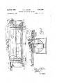
- FIGURE 1 is a front view of the improved apparatus of my invention, parts thereof being broken away and shown in section.
- FIGURE 2 is an end view of the apparatus of my invention with portions thereof being broken away and other portions in cross-section for clarification; said view illus trating the runners and pouring units supplied by the exit furnace of FIGURE 1;
- FIGURE 3 is a top plan view of the apparatus shown in FIGURES 1 and 2;
- FIGURE 4 is a diagrammatic view of the control means of the invention.
- the apparatus employed in the present invention comprises an entrance furnace, or reservoir 10, preferably supplied by a runner, as indicated at 11, from a melting furnace remotely located thereto (not shown).
- the said reservoir 10, through a conduit 12 located adjacent the bottom thereof, supplies molten metal supplied to it by the said melting furnace to a holding furnace 13 of relatively large size; said holding furnace supplies molten metal stored therein to an exit furnace or reservoir 15', through a conduit 14 located adjacent the bottom thereof.
- the furnace or reservoir 15 is adapted to provide molten metal to feed a pouring device or devices, such as designated at 16 and 17, as called upon, which device or devices communicate with the exit furnace or reservoir 15 as by runners 18 or the like.
- the holding furnace 13 is disclosed as a sealed drum with aligned inlet and outlet apertures 13a, 13b respectively, said apertures opening into the conduit 12, 14, of reservoirs and 15 respectively.
- the pressure within the holding hearth 13 is varied to maintain the metal level in the exit hearth or furnace 15 at a substantially constant heighth so that flow into the casting equipment, or pouring equipment, associated therewith is maintained at the desired rate.
- the exit hearth or furnace 15 is designed so that intermittent large demands from casting equipment will not, save in a slight degree, affect the level and, hence, the supply to other equipment associated therewith.
- the inlet hearth 10 is shown having a vertical heighth higher than the exit hearth 15 so that a metal head can be established therein to force metal into the holding chamber.
- the level of metal in the inlet hearth, or furnace 10, and the outlet hearth, or furnace 15, is approximately and substantially the same.
- Sensing means 22 for sensing the level of metal in the exit hearth 15 are shown in the preferred embodiment of my invention illustrated herein and said means are employed to sense and signal through control means 20, 21 pressure means shown at 25 provided for the control of pressure within the holding furnace on the molten metal.
- the probes or sensing devices 22, as shown in FIGURE 2, are disposed at such a level melt determined within the reservoir or exit discharge furnace 15 so that the holding furnace pressure means is signalled at any time the level in the reservoir 15 exceeds a normal predetermined level or falls below such level.
- Three probes or sensing devices are preferably utilized as shown and the tips of said sensors or probes are within close limits so that at all operative times a substantially constant supply of molten metal is available at the discharge reservoir 15.
- the sensing devices activate the pressure means located adjacent the holding furnace 13 through the control means 20, 21 and 22.
- the pressure means employed in the form herein comprises a centrifugal air blower 25 attached to the holding furnace 13 and has a conduit 26 connected to the hearth of the furnace at a point above the level 27 of the molten metal.
- Two solenoid operated valves 28 and 29, respectively, are used to regulate the pressure of the air delivered by the blower 25.
- the valves 28 and 29 are switched in such a way that one of them is opened when the other is closed.
- the valve 28 is connected to the open air by a tube 30.
- intake air is supplied to the blower by conduit means indicated at 31.
- the furnace units 10, 13 and 15 are all preferably heated, as by induction heaters 10', 13', and 15' and it is preferred that the covered runners shown at 18 in FIGURES 2 and 3 be heated as well. It is also to be noted that atmospheric pressure exists in both the exit an inlet hearths or furnaces, thus, equalizing the levels of both hearths so that the same are approximately equal. Only the relatively large melting or holding furnace 13 with a relatively small but sufficiently sized reservoir 15 and associated equipment are essential to the practice of this invention. As stated, the so-called holding furnace 13, as illustrated, could be a melting as Well as a holding furnace and, hence, the reservoir 10 dispensed with. The reservoir 10, if provided with induction heating of sufficient power could be utilized to melt the metal supply for the holding furnace.
- a constant metal level supply device for pouring means which comprises a furnace adapted to contain a large supply of molten metal, a discharge reservoir, one or more feeding troughs or runners connecting said discharge reservoir to said pouring means of various or similar demands, interconnecting means between said furnace and said reservoir through which said furnace supplies molten metal to said discharge reservoir, variable pressure means associated with said furnace adapted to exert pressure on molten metal in said furnace whereby molten metal may be supplied to the reservoir and the molten metal in said reservoir maintained at a constant supply level above the lower limit of the said troughs or runners to supply molten metal on demand to said pouring means, control means associated with said pressure means and said reservoir adapted to control the said pres sure means to maintain molten metal in the reservoir at the said constant supply level.
- a constant level metal supply for pouring means including a molten metal entrance reservoir, intercommunicating means between said entrance reservoir and said furnace whereby metal may be introduced into said furnace during operation thereof.
- a constant level metal supply for pouring means as claimed in claim 1, wherein the said furnace is a melting chamber.
Landscapes
- Engineering & Computer Science (AREA)
- Mechanical Engineering (AREA)
- Vertical, Hearth, Or Arc Furnaces (AREA)
- Casting Support Devices, Ladles, And Melt Control Thereby (AREA)
Description
April 29, 1969 R. A. SOMMER CONSTANT LEVEL HOLDING FURNACES Sheet INVENTOR. 42 2254 fi. SW BY iled March ll.
ATTORNEY.
Sheet of 2 Apri 29, 1969 R. A. SOMMER CONSTANT LEVEL HOLDING FURNACES Filed March 11. 1966 ATTORNEY.
INVENTOR. @4 4 4.
United States Patent Office 3,441,261 CONSTANT LEVEL HOLDING FURNACES Richard A. Sommer, Warren, Ohio, assignor to Ajax Magnethermic Corporation, Warren, Ohio, a corporation of Ohio Filed Mar. 11, 1966, Ser. No. 533,610 Int. Cl. CZlb 11/.00; B22c 19/04 US. Cl. 266-33 5 Claims ABSTRACT OF THE DISCLOSURE This invention relates to an improved apparatus for supplying pouring molten metal to a pouring device or devices and relates more particularly to improved holding and discharge vessels for molten metal, whereby a constant supply of molten metal for pouring equipment is ensured at all times at a discharge point to supply demands alternatively or simultaneously presented by various pouring units, etc., drawing therefrom. The apparatus involves the employment of a holding furnace storing large variable amounts of molten metal, continuously supplying molten metal to said discharge vessel as demands are made upon it, and maintaining a substantially uniform working level of metal therein.
A large holding furnace of the induction type which can store large variable amounts of molten metal, without tilting or tapping, is used in the apparatus of the invention and said furnace is connected to a reservoir or exit furnace, which reservoir preferably has induction heating means associated therewith, said reservoir stores a constant amount of heated molten metal and continuously supplies over long periods of time one or more pieces of pouring equipment drawing from the same variable or similar amounts of metal. The said reservoir is so designed that intermittent large demands from certain pouring equipment associated therewith does not effect the supply to other pouring equipment associated therewith.
The discharge reservoir signals to the holding furnace its needs as the demands are made upon it according to the invention and pressure on the molten metal in the holding furnace is increased or decreased accordingly to supply the proper amount of molten metal to the reservoir to maintain a substantially uniform working level of metal therein. The reservoir is so designed as to constitute a supply source of metal for the casting equipment or pouring furnaces, etc., proportioned to the amount of molten melt required to supply demands placed 'On it by the pouring equipment.
If molten metal is to be supplied to the equipment without interrupting the operation of the pouring equipment, an entrance induction heated furnace can be utilized. The level of molten metal in said entrance and exit furnace will be approximately the same and the pressure exerted on the metal in the holding furnace will maintain a level therein lower than the metal in such entrance and exit furnaces.
The preferred apparatus of my invention, although I do not wish to be restricted to a limited construction as to particular details thereof, involves the provision of a constant metal level supply for a pouring device or devices which includes a large molten metal holding furnace, a reservoir adjacent a discharge point for metal supplied thereto by the holding furnace, controlled steady variable pressure means exerting pressure upon the molten metal in the holding furnace to maintain a constant supply level in the molten metal discharge vessel or reservoir.
With a vast amount of metal in a large holding furnace and a plurality of demand pourers, it would be difficult to operate the prior art holding furnace having an inclined discharge conduit dispensing therefrom, such as that shown in US. Patent No. 2,936,326, dated May 10, 1960, or similar structures.
In the present construction, the discharge furnace or exit reservoir has a predetermined height of molten metal therein at all times, as demands are made upon the same, and this is sensed and communicated to control means wherefor pressure exerted on the molten metal in the holding furnace is varied to maintain a substantially constant supply level of metal in the discharge furnace, etc.
It is thus a principal object of my invention to provide improved storage for quantities of molten metal and to provide in conjunction therewith an auxiliary relatively smaller molten metal storage unit having discharge or delivery means adapted to supply, as required, demands of metal by pouring units associated therewith and to ensure a constant supply of molten metal for such needs.
A further object of this invention is to provide apparatus of the type referred to which is adapted for use with a holding furnace of great capacity, with less down time required for refill and with considerably longer operating time.
A still further object of this invention is to provide apparatus for constantly supplying a plurality of pouring devices with molten metal from a common source and Without interruption because of differences in the supply demand of the separate pourers.
Another object of this invention is to provide apparatus of the type referred to which will be efficient in opera.- tion, wherein demands are met, freezing of the metal in transit is prevented and continuous operation is assured.
Other objects of this invention and the invention itself will become more readily apparent by reference to the accompanying description, claims, and appended drawings, in which drawings:
FIGURE 1 is a front view of the improved apparatus of my invention, parts thereof being broken away and shown in section.
FIGURE 2. is an end view of the apparatus of my invention with portions thereof being broken away and other portions in cross-section for clarification; said view illus trating the runners and pouring units supplied by the exit furnace of FIGURE 1;
FIGURE 3 is a top plan view of the apparatus shown in FIGURES 1 and 2;
FIGURE 4 is a diagrammatic view of the control means of the invention.
Referring now to the drawings, in all of which like parts are designated by like reference characters, it will be seen that the apparatus employed in the present invention comprises an entrance furnace, or reservoir 10, preferably supplied by a runner, as indicated at 11, from a melting furnace remotely located thereto (not shown). The said reservoir 10, through a conduit 12 located adjacent the bottom thereof, supplies molten metal supplied to it by the said melting furnace to a holding furnace 13 of relatively large size; said holding furnace supplies molten metal stored therein to an exit furnace or reservoir 15', through a conduit 14 located adjacent the bottom thereof. The furnace or reservoir 15 is adapted to provide molten metal to feed a pouring device or devices, such as designated at 16 and 17, as called upon, which device or devices communicate with the exit furnace or reservoir 15 as by runners 18 or the like.
Patented Apr. 29, 1969 While the drawings indicate that the pouring devices 16, 17 associated with the apparatus of this invention are such as to be able to supply either large individual molds, as shown at 16, or to supply pouring furnaces having a plurality of discharge orifices as shown at 17, it will be obvious that other type pourers etc. could be used in lieu thereof.
It will be noted that the holding furnace 13 is disclosed as a sealed drum with aligned inlet and outlet apertures 13a, 13b respectively, said apertures opening into the conduit 12, 14, of reservoirs and 15 respectively.
By means of suitable controls 20, 21 the pressure within the holding hearth 13 is varied to maintain the metal level in the exit hearth or furnace 15 at a substantially constant heighth so that flow into the casting equipment, or pouring equipment, associated therewith is maintained at the desired rate.
The exit hearth or furnace 15 is designed so that intermittent large demands from casting equipment will not, save in a slight degree, affect the level and, hence, the supply to other equipment associated therewith. The inlet hearth 10 is shown having a vertical heighth higher than the exit hearth 15 so that a metal head can be established therein to force metal into the holding chamber. Generally, however, the level of metal in the inlet hearth, or furnace 10, and the outlet hearth, or furnace 15, is approximately and substantially the same. Sensing means 22 for sensing the level of metal in the exit hearth 15 are shown in the preferred embodiment of my invention illustrated herein and said means are employed to sense and signal through control means 20, 21 pressure means shown at 25 provided for the control of pressure within the holding furnace on the molten metal. The probes or sensing devices 22, as shown in FIGURE 2, are disposed at such a level melt determined within the reservoir or exit discharge furnace 15 so that the holding furnace pressure means is signalled at any time the level in the reservoir 15 exceeds a normal predetermined level or falls below such level. Three probes or sensing devices are preferably utilized as shown and the tips of said sensors or probes are within close limits so that at all operative times a substantially constant supply of molten metal is available at the discharge reservoir 15. The sensing devices, as hereinafter more fully described, activate the pressure means located adjacent the holding furnace 13 through the control means 20, 21 and 22. The pressure means employed in the form herein comprises a centrifugal air blower 25 attached to the holding furnace 13 and has a conduit 26 connected to the hearth of the furnace at a point above the level 27 of the molten metal. Two solenoid operated valves 28 and 29, respectively, are used to regulate the pressure of the air delivered by the blower 25. The valves 28 and 29 are switched in such a way that one of them is opened when the other is closed. The valve 28 is connected to the open air by a tube 30. As shown in FIGURE 2 of the drawings, intake air is supplied to the blower by conduit means indicated at 31. Although, in the foregoing it has been mentioned that air is used, there may be used any suitable gas.
Hence, as metal is drawn from the exit reservoir 15, by means of the automatic increase of pressure on the metal in the holding furnace as dictated by the draws or demands, additional metal is constantly supplied to the reservoir 15 thus constantly replenishing the supply of molten metal therein and holding a determined desired level for filling draw demands upon it. The pressure is automatically decreased by the signalling of sensors to the controls and to the pressure means when the volume in the holding furnace is increased sufficiently by a supply from the inlet furnace or reservoir 10, wherefore a substantially constant level of molten metal is maintained in the exit reservoir at all times,
It is contemplated that the furnace units 10, 13 and 15 are all preferably heated, as by induction heaters 10', 13', and 15' and it is preferred that the covered runners shown at 18 in FIGURES 2 and 3 be heated as well. It is also to be noted that atmospheric pressure exists in both the exit an inlet hearths or furnaces, thus, equalizing the levels of both hearths so that the same are approximately equal. Only the relatively large melting or holding furnace 13 with a relatively small but sufficiently sized reservoir 15 and associated equipment are essential to the practice of this invention. As stated, the so-called holding furnace 13, as illustrated, could be a melting as Well as a holding furnace and, hence, the reservoir 10 dispensed with. The reservoir 10, if provided with induction heating of sufficient power could be utilized to melt the metal supply for the holding furnace.
It will be apparent to those skilled in the art that the novel principles of the invention disclosed herein in connection with specific embodiments will suggest various other modifications and applications of the same, and it is to be understood that the various changes may be made without, however, departing from the spirit of the invention and the scope of the appended claims.
Having thus described the invention, What I claim as new and desire to be secured by Letters Patent is as follows:
1. A constant metal level supply device for pouring means which comprises a furnace adapted to contain a large supply of molten metal, a discharge reservoir, one or more feeding troughs or runners connecting said discharge reservoir to said pouring means of various or similar demands, interconnecting means between said furnace and said reservoir through which said furnace supplies molten metal to said discharge reservoir, variable pressure means associated with said furnace adapted to exert pressure on molten metal in said furnace whereby molten metal may be supplied to the reservoir and the molten metal in said reservoir maintained at a constant supply level above the lower limit of the said troughs or runners to supply molten metal on demand to said pouring means, control means associated with said pressure means and said reservoir adapted to control the said pres sure means to maintain molten metal in the reservoir at the said constant supply level.
2. A constant level metal supply for pouring means, as claimed in claim 1, including a molten metal entrance reservoir, intercommunicating means between said entrance reservoir and said furnace whereby metal may be introduced into said furnace during operation thereof.
3. A constant level metal supply for pouring means as claimed in claim 3, wherein the entrance reservoir is a melting furnace.
4. A constant level metal supply for pouring means, as claimed in claim 1, wherein the said furnace is a melting chamber.
5. A constant level molten metal supply for one or more molten metal pouring means as claimed in claim 1 wherein said discharge reservoir is open to the atmosphere.
References Cited UNITED STATES PATENTS 1,817,340 8/1931 Barr 2498l X 2,660,769 12/1953 Bennett l64-337 X 3,384,150 5/1968 Newsome 164-155 3,058,180 lO/l962 Port et al. l64l56 J. SPENCER OVERHOLSER, Primary Examiner. R. D. BALDWIN, Assistant Examiner.
U.S. Cl. X.R. l64l55, 337
Applications Claiming Priority (1)
| Application Number | Priority Date | Filing Date | Title |
|---|---|---|---|
| US53361066A | 1966-03-11 | 1966-03-11 |
Publications (1)
| Publication Number | Publication Date |
|---|---|
| US3441261A true US3441261A (en) | 1969-04-29 |
Family
ID=24126716
Family Applications (1)
| Application Number | Title | Priority Date | Filing Date |
|---|---|---|---|
| US533610A Expired - Lifetime US3441261A (en) | 1966-03-11 | 1966-03-11 | Constant level holding furnaces |
Country Status (3)
| Country | Link |
|---|---|
| US (1) | US3441261A (en) |
| DE (1) | DE1558161A1 (en) |
| GB (1) | GB1174963A (en) |
Cited By (7)
| Publication number | Priority date | Publication date | Assignee | Title |
|---|---|---|---|---|
| US3790145A (en) * | 1970-06-10 | 1974-02-05 | Graenges Essem Ab | Device in a melting or holding furnace for facilitating the charging thereof |
| US3791437A (en) * | 1969-12-13 | 1974-02-12 | Yaskawa Denki Seisakusho Kk | Method of controlling an electro-magnetic molten metal pouring device |
| US4200266A (en) * | 1977-09-02 | 1980-04-29 | Voest-Alpine Aktiengesellschaft | Mixing arrangement |
| US4220319A (en) * | 1978-05-31 | 1980-09-02 | Westofen Gmbh | Ovens |
| US4460163A (en) * | 1980-01-24 | 1984-07-17 | Stopinc Aktiengesellschaft | Device and furnace for discharging measured quantities of molten metal |
| US20060048913A1 (en) * | 2002-02-14 | 2006-03-09 | Hitoshi Mizuno | Container for supplying molten metal and safety device |
| RU2339886C2 (en) * | 2006-12-12 | 2008-11-27 | Открытое акционерное общество "Сибирский научно-исследовательский, конструкторский и проектный институт алюминиевой и электродной промышленности" (ОАО "СибВАМИ") | Melting and casting complex for teeming of aluminium and its alloys |
Families Citing this family (1)
| Publication number | Priority date | Publication date | Assignee | Title |
|---|---|---|---|---|
| RU2285879C1 (en) * | 2005-04-22 | 2006-10-20 | Открытое акционерное общество "Сибирский научно-исследовательский, конструкторский и проектный институт алюминиевой и электродной промышленности" (ОАО "СибВАМИ") | Melting-casting complex for aluminum and its alloys |
Citations (4)
| Publication number | Priority date | Publication date | Assignee | Title |
|---|---|---|---|---|
| US1817340A (en) * | 1929-08-03 | 1931-08-04 | Thomas B Barr | Casting apparatus |
| US2660769A (en) * | 1950-12-18 | 1953-12-01 | Dow Chemical Co | Die casting |
| US3058180A (en) * | 1961-10-11 | 1962-10-16 | Modern Equipment Co | Apparatus for pouring molten metal |
| US3384150A (en) * | 1964-10-26 | 1968-05-21 | Davy & United Eng Co Ltd | Continuous casting with controlled feeding from predetermined supply |
-
1966
- 1966-03-11 US US533610A patent/US3441261A/en not_active Expired - Lifetime
-
1967
- 1967-02-24 GB GB9038/67A patent/GB1174963A/en not_active Expired
- 1967-02-28 DE DE19671558161 patent/DE1558161A1/en active Pending
Patent Citations (4)
| Publication number | Priority date | Publication date | Assignee | Title |
|---|---|---|---|---|
| US1817340A (en) * | 1929-08-03 | 1931-08-04 | Thomas B Barr | Casting apparatus |
| US2660769A (en) * | 1950-12-18 | 1953-12-01 | Dow Chemical Co | Die casting |
| US3058180A (en) * | 1961-10-11 | 1962-10-16 | Modern Equipment Co | Apparatus for pouring molten metal |
| US3384150A (en) * | 1964-10-26 | 1968-05-21 | Davy & United Eng Co Ltd | Continuous casting with controlled feeding from predetermined supply |
Cited By (8)
| Publication number | Priority date | Publication date | Assignee | Title |
|---|---|---|---|---|
| US3791437A (en) * | 1969-12-13 | 1974-02-12 | Yaskawa Denki Seisakusho Kk | Method of controlling an electro-magnetic molten metal pouring device |
| US3790145A (en) * | 1970-06-10 | 1974-02-05 | Graenges Essem Ab | Device in a melting or holding furnace for facilitating the charging thereof |
| US4200266A (en) * | 1977-09-02 | 1980-04-29 | Voest-Alpine Aktiengesellschaft | Mixing arrangement |
| US4220319A (en) * | 1978-05-31 | 1980-09-02 | Westofen Gmbh | Ovens |
| US4460163A (en) * | 1980-01-24 | 1984-07-17 | Stopinc Aktiengesellschaft | Device and furnace for discharging measured quantities of molten metal |
| US20060048913A1 (en) * | 2002-02-14 | 2006-03-09 | Hitoshi Mizuno | Container for supplying molten metal and safety device |
| US7611664B2 (en) * | 2002-02-14 | 2009-11-03 | Hoei Shokai Co., Ltd. | Container for supplying molten metal and safety device |
| RU2339886C2 (en) * | 2006-12-12 | 2008-11-27 | Открытое акционерное общество "Сибирский научно-исследовательский, конструкторский и проектный институт алюминиевой и электродной промышленности" (ОАО "СибВАМИ") | Melting and casting complex for teeming of aluminium and its alloys |
Also Published As
| Publication number | Publication date |
|---|---|
| GB1174963A (en) | 1969-12-17 |
| DE1558161A1 (en) | 1970-03-19 |
Similar Documents
| Publication | Publication Date | Title |
|---|---|---|
| US3365242A (en) | Apparatus for discharging a gas from a container at a constant rate through several conduits | |
| US3441261A (en) | Constant level holding furnaces | |
| US3200457A (en) | Method of regulating the discharge of molten metal from ladles | |
| ES488262A1 (en) | PROCEDURE FOR CONTROLLING THE LIQUID FLOW TO A DESIRED LOW CAU-DAL, WITH ITS MAKING DEVICE | |
| EP0215514A3 (en) | Bathtub with improved hydromassage system | |
| US2674640A (en) | Apparatus for dispensing molten metal | |
| US2243425A (en) | Casting of metals and/or metal alloys and more particularly to a method of maintaining a uniform rate of flow of the molten mass into the mold or chill | |
| US3384150A (en) | Continuous casting with controlled feeding from predetermined supply | |
| KR900006046A (en) | Distributing device for molten metal | |
| US3050794A (en) | Furnace ladling apparatus | |
| US3807602A (en) | Method and apparatus for dispensing a fluidizable solid from a pressure vessel | |
| US3844453A (en) | Apparatus and method for melting and pouring metal | |
| US2936326A (en) | Method and apparatus for pressure metal dispensing | |
| US3592363A (en) | Device for adding fine particle-sized solids to a liquid stream | |
| US3221379A (en) | Furnaces | |
| US3504899A (en) | Melting or holding furnace structure utilizing pressurized gas for discharge of molten material | |
| US4328787A (en) | Method and arrangement for melting of pitch etc. | |
| NO783225L (en) | PROCEDURE FOR EXHAUSTING ADDITIONAL MATERIAL | |
| US3272225A (en) | Apparatus for watering plants | |
| US3471057A (en) | Apparatus for ladling liquid metal | |
| US3347427A (en) | Pressure pour apparatus | |
| US3187394A (en) | Apparatus for pouring molten metal into molds | |
| GB1463831A (en) | Furnace ladling apparatus and crucible | |
| US3497196A (en) | Device for introducing material into a degassing vessel for steel | |
| NO121511B (en) |