US3271908A - Dresser control for abrasive wheels - Google Patents
Dresser control for abrasive wheels Download PDFInfo
- Publication number
- US3271908A US3271908A US324609A US32460963A US3271908A US 3271908 A US3271908 A US 3271908A US 324609 A US324609 A US 324609A US 32460963 A US32460963 A US 32460963A US 3271908 A US3271908 A US 3271908A
- Authority
- US
- United States
- Prior art keywords
- grinding
- grinding wheel
- dressing
- relay
- dresser
- Prior art date
- Legal status (The legal status is an assumption and is not a legal conclusion. Google has not performed a legal analysis and makes no representation as to the accuracy of the status listed.)
- Expired - Lifetime
Links
Images


Classifications
-
- B—PERFORMING OPERATIONS; TRANSPORTING
- B24—GRINDING; POLISHING
- B24B—MACHINES, DEVICES, OR PROCESSES FOR GRINDING OR POLISHING; DRESSING OR CONDITIONING OF ABRADING SURFACES; FEEDING OF GRINDING, POLISHING, OR LAPPING AGENTS
- B24B53/00—Devices or means for dressing or conditioning abrasive surfaces
- B24B53/06—Devices or means for dressing or conditioning abrasive surfaces of profiled abrasive wheels
- B24B53/08—Devices or means for dressing or conditioning abrasive surfaces of profiled abrasive wheels controlled by information means, e.g. patterns, templets, punched tapes or the like
- B24B53/081—Devices or means for dressing or conditioning abrasive surfaces of profiled abrasive wheels controlled by information means, e.g. patterns, templets, punched tapes or the like by means of a template
-
- B—PERFORMING OPERATIONS; TRANSPORTING
- B24—GRINDING; POLISHING
- B24B—MACHINES, DEVICES, OR PROCESSES FOR GRINDING OR POLISHING; DRESSING OR CONDITIONING OF ABRADING SURFACES; FEEDING OF GRINDING, POLISHING, OR LAPPING AGENTS
- B24B5/00—Machines or devices designed for grinding surfaces of revolution on work, including those which also grind adjacent plane surfaces; Accessories therefor
- B24B5/36—Single-purpose machines or devices
- B24B5/42—Single-purpose machines or devices for grinding crankshafts or crankpins
Definitions
- This invention relates to a grinding machine, particularly a grinding machine used for crank grinding and other plunge grinding operations where shoulders or side walls must be ground, and more particularly to means for initiating the dressing operation in accordance with the needs of the grinding operation.
- the dressing operation in a grinding machine is usually performed between grinding operations.
- the time required for performing this operation is frequently greater than the time between successive grinding cycles and the beginning of the cycle must await the end of the dressing operation. To this extent, it is non-productive time. This non-productive time can be eliminated if the period between grinding cycles is not extended to wait for the completion of the dressing operation. The later portion of the dressing operation would thus be performed during the preliminary portion of the grinding cycle.
- radius as used here relates to rounded or curved corners on the grinding wheel which may or may not have a fixed radius.
- Another object is to provide a dressing apparatus having a dressing tool of the diamond roller type.
- Another object is to rotate said dressing tool in a plane approximately at right angles to the plane of the grinding wheel.
- Another object is to provide means for traversing said dressing tool across the face of said grinding wheel.
- Another object is to provide means for initiating operation of said dressing traverse means at any of a plurality of selected points in the grinding cycle.
- Another object is to provide means whereby a dwell period may be prolonged to permit the completion of a dressing or other operation.
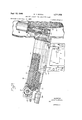
- FIG. 1 is an end elevation of a grinding machine to which the invention is applied.
- FIG. 2 is a sectional left hand elevation of the dressing apparatus.
- FIG. 3 is a plan view of the dressing mechanism showing the arrangement of ball guides and also the profile bar and follower for advancing and retracting the dressing roller.
- FIG. 4 is a plan view of the dressing mechanism showing different positions of the dressing roller to the grindig Wheel and the different positions of the follower and profile bar.
- FIG. 5 is an electric and hydraulic diagram.
- the bed of the machine is identified by numeral 10.
- Wheelbase 11 is slidably mounted on bed 10.
- Grinding wheel 12 is rotatably mounted on wheelbase 11.
- carriage 15 is slidably mounted for longitudinal movement relative to grinding wheel 12.
- Swivel table 16 on carriage 15 supports a headstock 17 and a footstock (not shown) which serve to rotatably support workpiece W.
- Steady rest frame 20 is pivotally mounted at 21 on bracket 22 on swivel table 16.
- Frame 20 is moved by said pivot 21 by means of piston 30 in cylinder 31.
- Piston 30 is connected to frame 20 by piston rod 32.
- Frame 20 carries a gage member 40 as well as work rest shoes (not shown).
- Grinding wheel 12 may be advanced and retracted relative to workpiece W either by hand wheel 45 or piston 50 in cylinder 51.
- piston 50 is attached to a portion 53 of wheelbase 11 by means of piston rod 52.
- piston rod 52 is part of or attached to a feed screw in the manner disclosed in Patent 2,486,244, granted October 25, 1949.
- the dressing device D is mounted on wheelbase 11 at the rear of grinding wheel 12.
- Dressing device D consists of a supporting bracket 60.
- the upper surface of bracket 60 is inclined in the direction of grinding wheel 12.
- Dressing device D also consists of housing 70 on which is slidably mounted a dressing bar 71.
- Dressing bar 71 may be advanced and retracted in housing 70 by means of hand wheel 75 and suitable gearing (not shown).
- Dressing bar 71 may be actuated automatically by any of several known devices for advancing dressing tools to compensate for reduction in wheel diameter.
- a diamond impregnated roller is rotatably mounted in housing 81 which is attached to bracket 82 on the right hand end of dressing bar 71.
- the support for roller 80 consists of shaft to which roller 80 is attached.
- Shaft 90 is rotatably supported on anti-friction bearings 91 in housing 81.
- Motor 92 is mounted on housing 81 in axial alignment with shaft 90.
- a coupling 93 connects motor 92 and shaft 90
- a supply of coolant for roller 80 is conducted through conduit and bore 101 in dresser bar 71 and a passage 102 in bracket 82.
- Housing 70 is slidably mounted on dresser carriage by means of ball guide 111.
- Dresser carriage 110 is, in turn, slidably mounted by means of ball guide 112 on stationary slide member 113 on bracket 60.
- Profile bar is attached to slide member 113.
- Follower member 121 is mounted on the underside of dresser bar 71 in operative relation with profile bar 120.
- the contacting surface of follower member 121 is curved to substantially the same radius as roller 80.
- the means for effecting the traverse movement of roller 80 relative to grinding wheel 12 is a hydraulic motor in the form of a cylinder 130. Piston 131 in cylinder is connected through piston rod 132 to dresser carriage 110.
- the means for insuring contact between follower memher 121 and profile bar 120 is a fluid pressure cylinder 140 connected to follower member 121 by means of piston rod 141.
- Relay contact 50CR2 closes to complete a circuit through normally closed rel-ay contact 51CR4 to energize solenoid A, shifting valve 150 to the left, to direct fluid to the head end of traverse cylinder 130 for the first pass of the dresser.
- limit switch 14LS closes to energize relay 51CR.
- Relay contact 51CR2 opens to deenergize relay 57CR.
- Relay contact 51CR5 closes to complete a circuit through relay contact 50CR3 to hold relay 50CR when relay contact 57CR2 opens. This also keeps the motor 92 in operation.
- Energizing relay SICR opens relay contact 51CR4 to deenergize valve solenoid A and closes relay contact 51CR3 to energize valve solenoid B, to shift valve 150 'to the right, to reverse the direction of movement of dresser traverse piston 131.
- Relay contact 51CR5 opens to deenergize relay SOCR and to stop motor 92.
- Relay contact 50CR3 opens to deenergize valve solenoid A and to prevent a repetition of the dressing operation.
- selector switch 155 is set to the #1 position.
- Gage member 40 acts when workpiece W is ground to the desired size to complete a circuit to energize relay 290R.
- Relay contact 29CR2 completes a circuit through contact l of selector switch 155 and through normally closed relay contact 51CR2 to energize relay 57CR. Energizing relay 57CR starts the dressing operation as described above.
- the ordinary time for initiating the dressing operation is when grinding wheel 12 is retracted to in-operative position.
- selector switch 155 is turned to the #2 position.
- limit switch contact 1LS2 When grinding wheel 12 is retracted, limit switch contact 1LS2 is closed and completes a circuit to energize relay 2CR.
- Relay contact 2CR1 energizes relay 17CR.
- Relay contact 17CR1 completes a circuit through con- :tact 2 of selector switch 155 to energize relay 57CR.
- grinding wheel 12 is advanced at a rapid rate by piston 50 to the point where it engages the side walls or cheeks of a crankpin.
- the advance movement of piston 50 is effected when relay 16CR (not shown), which is operable in conjunction with the work drive motor (not shown), is
- Relay contact 20CR1 completes a circuit to energize valve solenoid 8 to shift rapid feed pilot valve 170 to the left against spring 171 to direct fluid under pressure feed'cylinder 51.
- Piston 50 advances Wheelbase 11 rapidly to a point where grinding wheel 12 engages the shoulders or side walls of the part to be ground. At this point, the rate of advance is reduced by a dash pot or other suitable means (not shown).
- the corners and sides of grind-ing wheel 12 advance at a rate determined by the setting of the dash pot or other suitable means (not shown) to grind the shoulders or cheeks of a crankpin to the proper spacing.
- the corners of grinding wheel 12 perform the equivalent of a plunger grinding operation to a depth of A2" more or less, with a corresponding breakdown of the radius formed on said corners.
- the corners of grinding wheel 12 must form the radius between the body of the crankpin and the shoulders after the cheek grinding operation. It is, therefore, desirable in some instances to initiate the dressing operation at the end of the shoulder grinding operation in order to renew the radius on the corners of grinding wheel 12 to correct any breakdown in the corners of grinding wheel 12 which might have occurred during the check or shoulder grind-ing operation. In order to initiate a dressing operation at this time, selector switch should be set to the #3 position.
- rapid feed piston rod 52 engages positive stop 54 from which fluid under pressure is being discharged.
- the flow of fluid is stopped or restricted and the resulting increase in pressure in the conduit supplying said fluid may be used to operate pressure switch ZPS.
- Switch 2P8 completes a circuit through normally closed relay contact 22CR2 and normally closed relay contact 23CR2 to energize fast feed relay 21CR.
- Relay contact 21CR1 completes a circuit to energize valve solenoid 9.
- Valve solenoid 9 shifts the fast and slow feed valve to the right to direct fluid from pump 260 through fast feed throttle 181 to the right hand end of fast and and slow feed cylinder 190.
- Piston 191 consists of two heads connected by screw .192 which serves as a rack to rotate pinion or worm wheel 193 on hand wheel shaft 194.
- Relay contact 2'1-CR2 completes a circuit from relay contact 20CR3 through contact 3 on switch 155 to energize relay 57CR and to initiate the dressing operation at the end of the cheek or shoulder feed.
- Piston 191 continues the feed movement at a grinding rate during the dressing operation.
- the dressing operation may end before or during the round out operation when piston 191 stops for a predetermined interval as will be described later.
- switch contact 7PS1 completes a circuit to energize relay 22CR and round-out timer ITR.
- Relay 22CR is held by relay contact 22CR1.
- relay contact 22CR2 in the circuit to relay 21CR opens to deenergize relay 210R.
- relay 21CR When relay 21CR is deenergized, it opens the circuit through relay contact 21CR1 to deenergize valve solenoid 9.
- valve 180 moves to central position, stopping the fast feed piston 191 while the workpiece is still oversize.
- Timer contact 1TR2 closes a circuit through contact 4 of switch 155 and normally closed relay contact 51CR2 to energize relay 57CR to start the dressing operation when the wheel feed stops at said oversize position.
- Timer contact 1TR1 times closed at the end of the round-out period. However, feed relay 520R remains energized and relay contact 52CR1 remains open until the dresser returns to starting position when limit switch 14LS opens, deenergizing relay 51CR and opening relay contact 51CR1 to deenergize relay SZCR.
- Normally closed relay contact 52CR1 closes to complete a circuit through normally closed relay contact 21CR3 to energize relay 23CR.
- Relay contact 23CR1 closes to energize valve solenoid 10, shifting valve 180 to the left and connecting slow feed throttle 182 with fast feed cylinder 190 to continue the feed movement of piston 191 at a slower rate. Thus, resumption of the grinding feed is prevented until the dressing operation is completed. This is a conventional method of dressing. It is now considered more efficient to start the grinding cycle regardless of whether the dressing operation has been completed.
- the circuit shown in dotted line may be provided from timer contact 1TR1 through relay contact 21CR3 to relay 23CR. Simultaneous grinding and dressing will take place until the end of the dressing operation.
- conduit 196 directs fluid to pressure switch 8P8 which closes to complete a circuit through relay contact CR3 to energize timer ZTR.
- Timer contact 2TR1 times closed to complete a circuit through normally closed timer contact 3TR1 to energize relay 4TR.
- Timer 4TR times closed to energize timer 3TR and also to complete a circuit through relay contact 29CR1 to energize relay 26CR.
- Relay contact 26CR1 completes a circuit to energize incremental feed valve solenoid 13.
- Valve solenoid 13 moves valve 205 upwardly to connect the right hand end of cylinder 206 through reversing valve 207 with exhaust line 208.
- the left end of cylinder 206 is directly connected to a supply of air so that when the right hand end of cylinder 206 is connected to exhaust, the constant pressure at the left end of cylinder 206 will act on the smaller area of piston 209 to shift said piston and valve 207 to the right.
- the 'air supply will be connected through 'line 210 to the left end of cylinder 160, shifting piston 161 and feed pawl 166 to the right to rotate ratchet 168 to provide an incremental feed to feed screw 167.
- This feed movement is effected at a controlled rate by throttle valve 162 which controls the flow of exhaust fluid from the right hand end of cylinder 160.
- Timer relay 3TR opens after an interval sufficient to permit the operation of ratchet 168 and deenergizing timer relay 4TR.
- Timer relay contact 4TR1 opens to open the circuit through relay contact 29CR1 and deenergizes relay 26CR.
- Relay contact 26CR1 opens to deenergize valve solenoid 13, permitting valve 205 to move downwardly to connect pressure conduit 220 with the right hand end of cylinder 206, shifting piston 209 against the constant pressure in the left end of cylinder 206 to shift valve 207 to the left.
- Valve 207 then directs fluid under pressure through check valve 221 to the right hand end of cylinder 160 to move piston 161 to the left and reset paw-l 166.
- a grinding machine for grinding cylindrical workpieces, a bed, a grinding wheel support slidably mounted on said bed for movement transversely toward and from a workpiece, a grinding wheel rotatably mounted on said grinding wheel support, feeding means for effecting said transverse movement of said grinding wheel support toward and from said workpiece to perform a grinding operation, a dressing tool comprising a roller having embedded therein abrasive particles capable of dressing abrasive wheels, means for traversing said roller across the grinding wheel, a plurality of control means, means operable by said feeding means for successively actuating each of said control means at different points in said transverse movement for actuating said dresser traversing means while continuing said grinding operation, and selector means for determining at which point said dresser will be actuated.
- a grinding machine for grinding cylindrical workpieces, a bed, a grinding wheel support slidably mounted on said bed for movement transversely toward and from a workpiece, a grinding wheel rotatably mounted on said grinding wheel support, feeding means for effecting said transverse movement of said grinding wheel support to perform a grinding operation, a dressing tool, means for traversing said dressing tool across the grinding wheel, a plurality of control means actuated by said feeding means at different points in the transverse movement of said wheel support for actuating said dresser traversing means, and selector means operable in advance for connecting one of said control means with said dresser traversing means.
- a bed for grinding cylindrical workpieces, particularly workpieces having axially spaced shoulder portions and a radius between the cylindrical portions of the work and said shoulder portions, a bed, a work support mounted thereon having means for rotatably supporting a workpiece, a grinding wheel support slidably mounted on said bed for movement transversely toward and from said work support, a grinding Wheel rotatably mounted on said grinding wheel support, feeding means for advancing said grinding wheel support at a fast grinding rate, means to stop said fast grinding rate for a predetermined interval and thereafter to resume said feed at the same or at a different rate, a dressing mechanism comprising means for passing a dressing tool across the operative surface of said grinding wheel, means for periodically advancing said dressing tool toward said grinding wheel and said grinding wheel toward said workpiece to compensate for the dressing operation, a sizing device and means actuated by said sizing device at the end of the grinding cycle for initiating operation of dressing mechanism, and means operable before the beginning of a grinding cycle for selectively connecting said sizing device and said
- a grinding machine for grinding cylindrical workpieces, a bed, a work support, means for rotatably supporting a workpiece on said work support, a grinding wheel support slidably mounted on said bed for movement transversely toward and from said work support, a grinding wheel rotatably mounted on said grinding wheel support, means for effecting said transverse movement of said grinding wheel support toward and from said work support to effect a grinding operation, a sizing device for determining the end of said grinding operation, a dressing tool, and means for traversing said dressing tool across said grinding wheel, and a connection between said sizing device and said dresser traversing means for transmitting a signal from said sizing device to start said dresser traversing means.
- a grinding machine for grinding cylindrical workpieces, a bed, a work support, means for rotatably supporting a workpiece on said work support, a grinding wheel support slidably mounted on said bed for movement transversely toward and from said work support, a grinding wheel rotatably mounted on said grinding wheel support, means for effecting said transverse movement of said grinding wheel support toward and from said work support to effect a grinding operation, means operable at the end of a grinding operation to cause said transverse movement of said grinding wheel support away 'from said work support to back position, a dressing tool,
- control means actuated by said grinding wheel support in said back position, and selector means operable in advance of a grinding cycle for selectively and operably connecting said control means and said dresser traversing means.
- a bed for grinding cylindrical workpieces, particularly workpieces having axially spaced shoulder portions, and a radius between said cylindrical portion of the work and said shoulder portions, a bed, a work support mounted thereon having means for rotatably supporting a workpiece, a grinding wheel support slidably mounted on said bed for movement transversely toward and from said work support, a grinding wheel rotatably mounted on said grinding wheel support, feeding means for advancing said grinding wheel for grinding said shoulder portions, a dressing tool, means for traversing said dressing tool across said grinding Wheel, control means actuated by said feeding means after the grinding of said shoulder portions, and selector means connecting said dresser traversing means with said control means.
- a grinding machine for grinding cylindrical workpieces, a bed, a work support, means for rotatably supporting a workpiece on said Work support, a grinding wheel support slidably mounted on said bed for movement transversely toward and from said work support, a grinding wheel rotatably mounted on said grinding wheel support, means for effecting said transverse movement of said grinding wheel support toward and from said work support to eifect a grinding operation, means for stopping said transverse movement after a preliminary rough grinding operation, a dressing tool, means for traversing said dressing tool across said grinding wheel, and means including an electrical circuit actuated by said means for stopping said transverse movement, for starting said 'dresser traversing means.
- a grinding machine for grinding cylindrical workpieces, particularly workpieces having axially spaced shoulder portions, a bed, a work support mounted on said bed and having means for rotatably supporting a workpiece, a grinding wheel support slidably mounted on said bed for movement transversely toward and from said work support, a grinding wheel rotatably mounted on said grinding wheel support, feeding means for advancing said grinding wheel for grinding said shoulder portions, control means operable at the end of said shoulder grinding operation for causing a further advance of said wheel support to grind the cylindrical portion of the workpiece, a second control means to stop said feeding movement after a preliminary rough grinding operation,
- timing means to resume the feed after a predetermined interval
- size control means for stopping the advance of said wheel support and returning said wheel support to retracted or back position
- fourth control means actuated by said wheel support in said back position
- dressing tool means for traversing said dressing tool across said grinding wheel
- selector means connecting said dresser traversing means with one or another of said control means.
- a grinding machine for grinding cylindrical workpieces, particularly workpieces having axially spaced shoulder portions, a bed, a work support mounted on said bed and having means for rotatably supporting a workpiece,
- a grinding wheel support slidably mounted on said bed for movement transversely toward and from said work support, a grinding wheel rotatably mounted on said grinding wheel support, feeding means for advancing said grinding wheel for grinding said shoulder portions, control means operable at the end of said shoulder grinding operation for causing a further advance of said grinding Wheel support to grind the cylindrical portion of the workpiece, a dressing tool, and means actuated by said control means for starting said dresser traversing means.
- a grinding machine for grinding cylindrical workpieces, a bed, a work support, means for rotatably supporting a workpiece on said work support, a grinding wheel support slidably mounted on said bed for movement transversely toward and from said work support, a grinding wheel rotatably mounted on said grinding wheel support, means for effecting said transverse movement of said wheel support toward and from said work support to eifect a grinding operation, a sizing device for determining the end of said grinding operation, a dressing tool, means for traversing said dressing tool across said grinding wheel, and means for actuating said dresser traversing means comprising a motor and an electrical circuit connecting said sizing device and said motor.
Landscapes
- Engineering & Computer Science (AREA)
- Mechanical Engineering (AREA)
- Grinding Of Cylindrical And Plane Surfaces (AREA)
- Grinding-Machine Dressing And Accessory Apparatuses (AREA)
Priority Applications (4)
| Application Number | Priority Date | Filing Date | Title |
|---|---|---|---|
| US324609A US3271908A (en) | 1963-11-15 | 1963-11-15 | Dresser control for abrasive wheels |
| SE13516/64A SE321161B (de) | 1963-11-15 | 1964-11-10 | |
| DE1502490A DE1502490C3 (de) | 1963-11-15 | 1964-11-16 | Steuereinrichtung für den Schleifschlitten und das Abrichtwerkzeug einer Schleifmaschine |
| JP6471664A JPS5318756B1 (de) | 1963-11-15 | 1964-11-16 |
Applications Claiming Priority (1)
| Application Number | Priority Date | Filing Date | Title |
|---|---|---|---|
| US324609A US3271908A (en) | 1963-11-15 | 1963-11-15 | Dresser control for abrasive wheels |
Publications (1)
| Publication Number | Publication Date |
|---|---|
| US3271908A true US3271908A (en) | 1966-09-13 |
Family
ID=23264336
Family Applications (1)
| Application Number | Title | Priority Date | Filing Date |
|---|---|---|---|
| US324609A Expired - Lifetime US3271908A (en) | 1963-11-15 | 1963-11-15 | Dresser control for abrasive wheels |
Country Status (4)
| Country | Link |
|---|---|
| US (1) | US3271908A (de) |
| JP (1) | JPS5318756B1 (de) |
| DE (1) | DE1502490C3 (de) |
| SE (1) | SE321161B (de) |
Cited By (2)
| Publication number | Priority date | Publication date | Assignee | Title |
|---|---|---|---|---|
| US3603044A (en) * | 1969-06-10 | 1971-09-07 | Litton Industries Inc | Gauge mechanism for grinding machines |
| US4274388A (en) * | 1979-10-15 | 1981-06-23 | The Warner & Swasey Company | Method and apparatus for dressing grinding wheels |
Families Citing this family (1)
| Publication number | Priority date | Publication date | Assignee | Title |
|---|---|---|---|---|
| DE3529427A1 (de) * | 1985-08-16 | 1987-02-26 | Fortuna Werke Maschf Ag | Verfahren und vorrichtung zum einleiten eines abrichtvorganges einer schleifscheibe in abhaengigkeit von deren stumpfungsgrad |
Citations (9)
| Publication number | Priority date | Publication date | Assignee | Title |
|---|---|---|---|---|
| US2556843A (en) * | 1944-07-07 | 1951-06-12 | Landis Tool Co | Grinding machine |
| US2720062A (en) * | 1948-05-14 | 1955-10-11 | Fouquet Eugene | Grinding machines |
| US2720063A (en) * | 1953-05-29 | 1955-10-11 | Norton Co | Multiple wheel grinding machine |
| US2813378A (en) * | 1955-07-27 | 1957-11-19 | Norton Co | Cam grinding machine |
| US2851827A (en) * | 1957-11-08 | 1958-09-16 | Norton Co | Multiple wheel grinding machine |
| US2882651A (en) * | 1957-10-18 | 1959-04-21 | Gardner Machine Co | Positioning abrasive discs for dressing |
| US2889665A (en) * | 1957-10-07 | 1959-06-09 | Wilbur F Jessup | Compensating device for grinding machines |
| US2926651A (en) * | 1957-09-20 | 1960-03-01 | Landis Tool Co | Abrasive wheel forming and dressing apparatus |
| US2930371A (en) * | 1957-10-02 | 1960-03-29 | Jones & Lamson Mach Co | Grinding wheel dressing device |
-
1963
- 1963-11-15 US US324609A patent/US3271908A/en not_active Expired - Lifetime
-
1964
- 1964-11-10 SE SE13516/64A patent/SE321161B/xx unknown
- 1964-11-16 DE DE1502490A patent/DE1502490C3/de not_active Expired
- 1964-11-16 JP JP6471664A patent/JPS5318756B1/ja active Pending
Patent Citations (9)
| Publication number | Priority date | Publication date | Assignee | Title |
|---|---|---|---|---|
| US2556843A (en) * | 1944-07-07 | 1951-06-12 | Landis Tool Co | Grinding machine |
| US2720062A (en) * | 1948-05-14 | 1955-10-11 | Fouquet Eugene | Grinding machines |
| US2720063A (en) * | 1953-05-29 | 1955-10-11 | Norton Co | Multiple wheel grinding machine |
| US2813378A (en) * | 1955-07-27 | 1957-11-19 | Norton Co | Cam grinding machine |
| US2926651A (en) * | 1957-09-20 | 1960-03-01 | Landis Tool Co | Abrasive wheel forming and dressing apparatus |
| US2930371A (en) * | 1957-10-02 | 1960-03-29 | Jones & Lamson Mach Co | Grinding wheel dressing device |
| US2889665A (en) * | 1957-10-07 | 1959-06-09 | Wilbur F Jessup | Compensating device for grinding machines |
| US2882651A (en) * | 1957-10-18 | 1959-04-21 | Gardner Machine Co | Positioning abrasive discs for dressing |
| US2851827A (en) * | 1957-11-08 | 1958-09-16 | Norton Co | Multiple wheel grinding machine |
Cited By (2)
| Publication number | Priority date | Publication date | Assignee | Title |
|---|---|---|---|---|
| US3603044A (en) * | 1969-06-10 | 1971-09-07 | Litton Industries Inc | Gauge mechanism for grinding machines |
| US4274388A (en) * | 1979-10-15 | 1981-06-23 | The Warner & Swasey Company | Method and apparatus for dressing grinding wheels |
Also Published As
| Publication number | Publication date |
|---|---|
| DE1502490C3 (de) | 1974-06-27 |
| SE321161B (de) | 1970-02-23 |
| DE1502490B2 (de) | 1973-11-29 |
| DE1502490A1 (de) | 1971-09-16 |
| JPS5318756B1 (de) | 1978-06-16 |
Similar Documents
| Publication | Publication Date | Title |
|---|---|---|
| US3197921A (en) | Grinding machine | |
| US2429830A (en) | Grinding machine | |
| US2639562A (en) | Precision locating device | |
| US3327432A (en) | Grinding machine | |
| US3812623A (en) | Internal grinding machine | |
| US3271908A (en) | Dresser control for abrasive wheels | |
| US3535828A (en) | Grinding machine | |
| GB1097404A (en) | Automatic or semi-automatic multi-spindle grinder for diesel engine fuel nozzles and method of employing said machine | |
| US2984952A (en) | Pressure operated feed control for grinding machines | |
| US3019562A (en) | Grinding machine with dual purpose grinding wheels | |
| GB1247870A (en) | Machine for simultaneously performing machining operations on the centre bore and at least one end face of a rotatable workpiece | |
| GB431288A (en) | Improvements in or relating to grinding machines | |
| GB952065A (en) | Method and apparatus for grinding | |
| US3524283A (en) | Grinding machinery | |
| US3247620A (en) | Multiple position feed mechanism | |
| US3033187A (en) | Wheel wear sensing device and compensator | |
| US2708816A (en) | Tapered cam grinder | |
| US3271905A (en) | Master cam actuator | |
| US3153884A (en) | Apparatus for grinding flexible workpieces | |
| US2127856A (en) | Grinding machine | |
| US2248172A (en) | Race grinder | |
| US2899778A (en) | Automatic grinding cycle | |
| JPS6119910Y2 (de) | ||
| US2782565A (en) | Valve grinder | |
| US1731719A (en) | Grinding machine |