US3208564A - Window - Google Patents
Window Download PDFInfo
- Publication number
- US3208564A US3208564A US205646A US20564662A US3208564A US 3208564 A US3208564 A US 3208564A US 205646 A US205646 A US 205646A US 20564662 A US20564662 A US 20564662A US 3208564 A US3208564 A US 3208564A
- Authority
- US
- United States
- Prior art keywords
- window
- members
- glass
- flange
- frame
- Prior art date
- Legal status (The legal status is an assumption and is not a legal conclusion. Google has not performed a legal analysis and makes no representation as to the accuracy of the status listed.)
- Expired - Lifetime
Links
- 229910052751 metal Inorganic materials 0.000 claims description 29
- 239000002184 metal Substances 0.000 claims description 29
- 229920003023 plastic Polymers 0.000 claims description 22
- 239000004033 plastic Substances 0.000 claims description 22
- 239000011521 glass Substances 0.000 description 30
- 238000010276 construction Methods 0.000 description 14
- 238000007789 sealing Methods 0.000 description 6
- 229910052782 aluminium Inorganic materials 0.000 description 5
- XAGFODPZIPBFFR-UHFFFAOYSA-N aluminium Chemical compound [Al] XAGFODPZIPBFFR-UHFFFAOYSA-N 0.000 description 5
- 238000009432 framing Methods 0.000 description 4
- 239000007787 solid Substances 0.000 description 3
- 230000015572 biosynthetic process Effects 0.000 description 2
- 230000000694 effects Effects 0.000 description 2
- 239000005357 flat glass Substances 0.000 description 2
- 239000000463 material Substances 0.000 description 2
- 229920000915 polyvinyl chloride Polymers 0.000 description 2
- 239000004800 polyvinyl chloride Substances 0.000 description 2
- 230000005855 radiation Effects 0.000 description 2
- 230000000717 retained effect Effects 0.000 description 2
- 241001664469 Tibicina haematodes Species 0.000 description 1
- AZDRQVAHHNSJOQ-UHFFFAOYSA-N alumane Chemical group [AlH3] AZDRQVAHHNSJOQ-UHFFFAOYSA-N 0.000 description 1
- 230000005494 condensation Effects 0.000 description 1
- 238000009833 condensation Methods 0.000 description 1
- 238000001816 cooling Methods 0.000 description 1
- 229920002457 flexible plastic Polymers 0.000 description 1
- 238000007710 freezing Methods 0.000 description 1
- 230000008014 freezing Effects 0.000 description 1
- 230000000266 injurious effect Effects 0.000 description 1
- 230000035515 penetration Effects 0.000 description 1
Images
Classifications
-
- E—FIXED CONSTRUCTIONS
- E06—DOORS, WINDOWS, SHUTTERS, OR ROLLER BLINDS IN GENERAL; LADDERS
- E06B—FIXED OR MOVABLE CLOSURES FOR OPENINGS IN BUILDINGS, VEHICLES, FENCES OR LIKE ENCLOSURES IN GENERAL, e.g. DOORS, WINDOWS, BLINDS, GATES
- E06B3/00—Window sashes, door leaves, or like elements for closing wall or like openings; Layout of fixed or moving closures, e.g. windows in wall or like openings; Features of rigidly-mounted outer frames relating to the mounting of wing frames
- E06B3/30—Coverings, e.g. protecting against weather, for decorative purposes
- E06B3/301—Coverings, e.g. protecting against weather, for decorative purposes consisting of prefabricated profiled members or glass
- E06B3/305—Covering metal frames with plastic or metal profiled members
-
- E—FIXED CONSTRUCTIONS
- E06—DOORS, WINDOWS, SHUTTERS, OR ROLLER BLINDS IN GENERAL; LADDERS
- E06B—FIXED OR MOVABLE CLOSURES FOR OPENINGS IN BUILDINGS, VEHICLES, FENCES OR LIKE ENCLOSURES IN GENERAL, e.g. DOORS, WINDOWS, BLINDS, GATES
- E06B1/00—Border constructions of openings in walls, floors, or ceilings; Frames to be rigidly mounted in such openings
- E06B1/04—Frames for doors, windows, or the like to be fixed in openings
- E06B1/34—Coverings, e.g. protecting against weather, for decorative purposes
- E06B1/342—Reveal covering members disposed alongside of a window frame
-
- E—FIXED CONSTRUCTIONS
- E06—DOORS, WINDOWS, SHUTTERS, OR ROLLER BLINDS IN GENERAL; LADDERS
- E06B—FIXED OR MOVABLE CLOSURES FOR OPENINGS IN BUILDINGS, VEHICLES, FENCES OR LIKE ENCLOSURES IN GENERAL, e.g. DOORS, WINDOWS, BLINDS, GATES
- E06B3/00—Window sashes, door leaves, or like elements for closing wall or like openings; Layout of fixed or moving closures, e.g. windows in wall or like openings; Features of rigidly-mounted outer frames relating to the mounting of wing frames
- E06B3/32—Arrangements of wings characterised by the manner of movement; Arrangements of movable wings in openings; Features of wings or frames relating solely to the manner of movement of the wing
- E06B3/34—Arrangements of wings characterised by the manner of movement; Arrangements of movable wings in openings; Features of wings or frames relating solely to the manner of movement of the wing with only one kind of movement
- E06B3/42—Sliding wings; Details of frames with respect to guiding
- E06B3/44—Vertically-sliding wings
- E06B2003/4438—Vertically-sliding wings characterised by the material used for the frames
- E06B2003/4453—Metal
-
- E—FIXED CONSTRUCTIONS
- E06—DOORS, WINDOWS, SHUTTERS, OR ROLLER BLINDS IN GENERAL; LADDERS
- E06B—FIXED OR MOVABLE CLOSURES FOR OPENINGS IN BUILDINGS, VEHICLES, FENCES OR LIKE ENCLOSURES IN GENERAL, e.g. DOORS, WINDOWS, BLINDS, GATES
- E06B3/00—Window sashes, door leaves, or like elements for closing wall or like openings; Layout of fixed or moving closures, e.g. windows in wall or like openings; Features of rigidly-mounted outer frames relating to the mounting of wing frames
- E06B3/32—Arrangements of wings characterised by the manner of movement; Arrangements of movable wings in openings; Features of wings or frames relating solely to the manner of movement of the wing
- E06B3/34—Arrangements of wings characterised by the manner of movement; Arrangements of movable wings in openings; Features of wings or frames relating solely to the manner of movement of the wing with only one kind of movement
- E06B3/42—Sliding wings; Details of frames with respect to guiding
- E06B3/44—Vertically-sliding wings
- E06B2003/4476—Coverings, e.g. for protecting against weather or for decorative purposes
-
- E—FIXED CONSTRUCTIONS
- E06—DOORS, WINDOWS, SHUTTERS, OR ROLLER BLINDS IN GENERAL; LADDERS
- E06B—FIXED OR MOVABLE CLOSURES FOR OPENINGS IN BUILDINGS, VEHICLES, FENCES OR LIKE ENCLOSURES IN GENERAL, e.g. DOORS, WINDOWS, BLINDS, GATES
- E06B3/00—Window sashes, door leaves, or like elements for closing wall or like openings; Layout of fixed or moving closures, e.g. windows in wall or like openings; Features of rigidly-mounted outer frames relating to the mounting of wing frames
- E06B3/32—Arrangements of wings characterised by the manner of movement; Arrangements of movable wings in openings; Features of wings or frames relating solely to the manner of movement of the wing
- E06B3/34—Arrangements of wings characterised by the manner of movement; Arrangements of movable wings in openings; Features of wings or frames relating solely to the manner of movement of the wing with only one kind of movement
- E06B3/42—Sliding wings; Details of frames with respect to guiding
- E06B3/44—Vertically-sliding wings
- E06B3/4407—Single-hung, i.e. having a single vertical sliding panel
Definitions
- This invention relates to a window, particularly a metal Window of the type adapted to be located in buildlngs.
- metal windows have a certain stark appearance because of the metal.
- the window of this invention avoids these difliculties, as means are provided not only to substantially inhibit condensate formation on the inner surfaces but also to provide a better appearance in the window.
- One of the features of this invention therefore is to provide an improved window construction having a better appearance and in which condensation of moisture during the cold winter months is either completely prevented or at least materially reduced.
- FIGURE 1 is an elevational view of the exterior side of a window embodying the invention.
- FIGURE 2 is an elevational view of the interior side of the window.
- FIGURE 3 is a fragmentary sectional elevational view of the window and associated structure taken substan tially along line 3-3 of FIGURE 1.
- FIGURE 4 is a horizontal sectional elevational view through the window and associated structure with the sash partially raised in order that the section illustrates both the side construction of the sash and the side construction of the fixed glass.
- FIGURE 5 is a vertical sectional view of the window and associated structure taken substantially along line 5-5 of FIGURE 1.
- FIGURE 6 is a vertical sectional view taken substantially along line 66 of FIGURE 1.
- FIGURE 7 is a vertical sectional view through another embodiment of the invention showing means for stacking two windows vertically.
- FIGURE 8 is a horizontal sectional view through a third embodiment of the invention showing means for connecting two windows side-by-side.
- the window frame is made up of aluminum parts joined together to form a head rail 10, a sill rail 11 a pair of side jamb rails 12.
- Each of these rails is preferably of extruded aluminum construction and is provided with attaching means for attaching the frame to adjoining portions of the wall.
- the head rail has a vertical wind break 13 adapted to be located inwardly of an outside wall member 14 and an outwardly extending web 15 on the exterior of the wall 16.
- the head rail is also provided with an inwardly exice tending web 17 substantially coplanar with the outer web 15 provided on its inner end with a pair of parallel flanges 18 and 19 between which is positioned one edge of a wall surface member 28.
- Each jamb rail 12, as shown in FIGURE 4, is constructed to have an outside box section 20 of generally rectangular horizontal cross section with this box section including an outwardly extending web 21 and a removable wind break.
- This removable wind break 22 has a foot flange 23 normally held between spaced brackets 24 and 25 having inturned edges adapted to retain the flange 23.
- the brackets 24 and 25 extend toward each other so that the foot flange 23 may be slid between them longitudinally to attach the wind break 22 in position.
- the brackets 24 and 25 are integral with an inwardly extending web 26 having on its inner end a pair of parallel flanges 27 adapted to receive one edge of a member 29 similar to the member 28.
- the sill rail 11 is also provided with a wind break 30 similar to the wind breaks 13 and 22.
- the wind break 30 extends downwardly from the main portion 31 of the sill which is of outwardly and downwardly sloped stepped construction.
- the outer end of this sill is provided with a downward extending flange 32 while the inner end is provided with a pair of depending feet 33 and 34 adapted to rest on the subconstruction 35.
- the foot 34 is provided with a flange 36 spaced from the inner edge 37 of the rail in order to support one edge of a construction member 38 similar to the members 28 and 29.
- the window is provided with a transverse transom 39 also of aluminum with the transom including an inwardly, upwardly extending portion 40 provided with a forked construction 41 at the top to retain a sealing gasket 42.
- the transom 39 also has a horizontally outwardly extending portion 43 provided at its outer edge with an upwardly and inwardly extending hook 44.
- the transom 39, side jamb webs 21 and head rail web 15 have a fixed window glass 45 located within the frame tormed by these parts.
- a plastics glazing strip 46 In order to retain the fixed glass 45 in position, there is provided a plastics glazing strip 46.
- the glazing strip 46 is, of course, on the exterior side of the glass 45 and has a first portion 47 engaging the glass 45 and a second portion 48 engaging the above-described frame formed by the members 15, 21 and 39.
- This second portion 48 is provided with a hooked end 49 for engaging the hook 44 and similar hooks 50 and 51 on the members 15 and 21, respectively.
- the first portion 47 of the glazing strip 46 comprises two spaced parts 52 and 53, one of which 53 bears against an edge of the glass 45 and the other of which 52 bears against the side of the glass adjacent the edge.
- the parts 52 and 53 are distorted away from each other by the glass in order that firm holding pressure is applied to the glass.
- the two portions 47 and 48 of the strip are distorted toward each other when the glazing strip is in position in order that the resiliency of the plastics strip will apply holding pressure to the glass 45.
- the various plastics parts of the window of this invention may of course be made from any weather resistant, solid, resilient plastics described and in a particular embodiment solid polyvinyl chloride is used.
- cover members of low heat conductivity substantially entirely covering the interior side of the window. These cover members are joined to the metal members of the window at spaced areas of minor extent with the cover members being otherwise spaced from the metal members to provide heat insulating spaces therebetween. Such spaces maintain the cover members at a relatively warm temperature so that injurious condensate does not form even in the most severe winter weather.
- the head rail is provided with a plastics cover member 54 attached to the head rail at only the side edges of the cover member.
- the inner edge of the cover member 54 is provided with a pair of spaced parallel inwardly directed hooked flanges 55 with the hooks extending toward each other and adapted to engage the opposite sides of a headed metal flange 56.
- the outer edge of the cover member 54 is provided with an inwardly directed hooked flange 57 adapted to be located between a pair of spaced parallel metal flanges 58.
- the flange construction is such that the cover member 54 itself hides all of the flanges from view and the flanges not only fasten the cover member in place but also space the cover member to provide internal insulating space 59 between the head rail and the cover member.
- This cover member 61 is of channel construction and fits over a ribbed flange 62 on the inner end of the sill rail 11.
- the side jamb rails 12 are similarly provided with plastics cover members which not only insulate the inner portions of the metal window frame but also provide guideways for the vertically movable sash 60.
- the cover member 63 is of right angle construction and arranged substantially parallel to the right angle construction of the web 26 and of the web 64 that forms the inner side of the box section 20.
- the cover member 63 has one side 65 substantially parallel to the window frame web 26 and is provided with inwardly spaced substantially parallel brackets 66 with inwardly extending spurs engaging the opposite sides of a spurred flange 67 that is formed integrally with the web 26.
- the opposite side of the cover member 63 is held by means of a web 68 provided with an inwardly directed spur cooperating with a spurred flange 69 that is integral with the side jamb 12.
- the inner end of the jamb is provided with its cover member 70 that is attached to the inner end of the jamb web 26 by means of a pair of parallel inwardly spurred cover member flanges 71 engaging similar flanges integral with the web 26 and located between the flanges 71.
- the cover member 70 and cover member 63 cooperate to provide side guides for the sash 60.
- Cover member 63 is provided with gaskets '72 and 73 preferably of felt to bear against the side and edge respectively of the sash to seal the sash and frame against penetration by outside weather elements.
- the sash 60 includes window glass 74 which like the glass 45 is preferably of the thermal insulating type in which two spaced sheets of glass are joined together at the edges to form an insulating air space therebetween.
- the glass 74 is provided with a framing 75 enclosing the edges of the glass.
- This framing is also a plastics material as described above and is constructed of interlocking inner 76 and outer 77 parts that grip the edges of the glass therebetween.
- the outer stile part 77 is provided with an inner end 82 that presses against the side of the glass 74.
- This part 77 is also provided with an outwardly extending flange 78 that makes sealing contact with the gasket 42 on the transom 39 when the window 60 is closed.
- a hook member 79 Extending inwardly of the flange 78 is a hook member 79 having a lower end adapted to make locking engagement with a hook 80 on the outer edge of a flange 81 that extends outwardly from the inner stile part 76.
- This inner stile part also has an inner end or flange 83 whose edge bears against the inner surface of the glass 74.
- the hook member 79 on the outer stile part 77 is received between the flange 81 and an outer flange 84 also formed integrally with the outer stile part 77.
- the outer end of this flange 84- bears against a step 85 on the inner stile part 76 so as to lock the two parts together.
- the flange ends 82 and 83 are distorted outwardly by their pressure against the sides of the glass 74 from their normal unstressed conditions so as to apply sealing pressure to the sides of the glass.
- the sides of the framing 75 is substantially the same as the top, as shown in FIG- URE 6, but with the omission of the flange 78.
- the bottom of the framing 75 is substantially the same as the top except for the extension of the inner and outer stile parts into parallel members 86 and 87 with the inner member 87 provided with an integral handle portion 88 and the outer member 86 provided with a pair of spaced inwardly directed arcuate flanges 89 adapted to receive the barbed inner end of a flange member 90 to lock the lower ends of the members 86 and 87 together.
- This flange member 90 also holds a gasket 91 for sealing against the top surface of the sill rail 11 when the sash 60 is closed.
- the cover member 61 on the sill rail 11 carries on its outer surface a gasket 120 also preferably of felt similar to the gaskets 72 and 73 and attached in a similar manner.
- the inside of the wall 16 surrounding the window is framed by a plastics part 92 for both construction and decorative purposes.
- cover members that not only provide a decorative appearance but are also spaced from the metal parts to provide an insulating space therebetween.
- the insulating effect of the cover members is not exactly understood but it is believed to be more than the mere provision of a dead air space. Observations have indicated that it may be that the cover members absorb heat from the room by radiation and convection and then project this heat by radiation into the air space between the metal and the plastics. This appears to set up a slightly warmer air bubble zone which has a positive internal pressure to prevent the passage or circulation of moisture laden room air.
- cover members are preferably solid polyvinyl chloride. These members cover all metal parts of the frame which is preferably of aluminum that are exposed to the room. In addition, it is preferred that plastics glazing strips be used as described in order to present a pleasing appearance to the exterior.
- FIGURE 7 illustrates how this window construction can be used to provide stacked units one on top of the other.
- a sill rail 11 is located above a head rail 10 and the two are connected together by means of a metal connecting member 93 preferably of extruded aluminum.
- This connecting member is provided with a horizontal base piece 94 having an outer vertical web 95 and an inner vertical web 96.
- the upper end of the outer web 95 is provided with a locking groove section 97 receiving the lower end of the outer flange 32 to retain the outer end of the sill rail 11.
- the upper end of the inner vertical web 96 is provided with inwardly spurred upper and lower parallel flanges 98 for receiving the spurred flange 36. This serves to retain securely the inner end of the sill 11.
- the center of the sill is supported by providing upwardly extending parallel flanges 99 at an intermediate area with the connecting member 93 embracing the opposite sides of the bottom of the Wind break 30.
- the bottom end of the outer vertical web 95 is provided with parallel inwardly extending flanges 100 the lowermost of which is inwardly spurred to retain in position the downwardly extending flange 101 on the outer end of the head rail 10.
- the bottom of the inner vertical web 96 is provided with inwardly spurred flanges 102 similar to the opposite flanges 98 in order to receive the spurred flange 18 and thereby lock securely the inner end of the head rail 10.
- This assembly is provided with its plastics cover member 103 that is locked in position at the top by means of an inwardly spurred outwardly extending flange 104 that is received between the upper spurred flange 98 and the inner end 37 of the sill.
- the lower end of the cover member 103 is provided with a similar outwardly extending spurred flange 105 that is held between the lower spurred flange 102 and the inner end 106 of the head rail 10.
- FIGURE 8 discloses an embodiment in which the adjacent side jambs of two adjacent windows may be attached together to form a side-by-side construction.
- the wind breaks 22 are removed to leave inwardly directed flanges 107.
- the two flanges are in contact with each other as shown in FIGURE 8. They are then locked together by means of an inwardly flanged channel member 108 of metal, preferably extruded aluminum.
- flanges 27 on the opposite sides of the jambs are similarly in contact with each other and locked together by a channel member 109 like the channel member 108.
- cover member 110 of plastics material having inwardly directed spurred flanges 111 receiving and locked around the channel member 109.
- the cover member 110 also has sloped side parts ;12 extending toward and contacting the cover members
- a window having an exterior side and an interior side comprising: metal members joined together to form a frame having a head, side jambs, and a sill; a movable sash comprising a glass pane and a rigid plastics stile enclosing the edge of the pane and having side rails, a bottom rail and a top rail; and cover members of low heat conductivity covering the interior side of said frame, said sash moving within and in contact with said cover members to be guided thereby.
- a window having an exterior side and an interior side comprising: metal members joined together to form a frame having a head, side jambs and a sill; a movable sash comprising a glass pane and a rigid plastics stile enclosing the edge of the pane and having side rails, a bottom rail and a top rail; and cover members of low heat conductivity covering the interior side of said frame said sash moving within and in contact with said cover members to be guided thereby, certain of said cover members carrying gasket members against which said sash bears.
- a window having an exterior side and an interior side comprising: metal members joined together to form a frame having a head, side jambs, a sill, and a transom; a movable sash comprising a glass pane and a plastics stile enclosing the edge of the pane and having side rails, a bottom rail and a top check rail carrying an outwardly extending ledge for making sealing engagement with said transom on closing of said sash, said stile including an outer part and an inner part each having a glass bearing portion and an interlocked portion for holding said parts in interlocked relationship; and cover members of low heat conductivity covering the interior side of said frame within which said sash moves, certain of said cover members carrying gasket members against which said sash bears.
- a window having an exterior side for exposure to outside air and an interior side for exposure to inside air comprising: metal members joined together to form a frame having a head, side jambs, and a sill; a connecting member joining the head of one frame to the sill of another frame to form a pair of stacked windows, said connecting member having interlocking connections to said head and sill; and a plastics cover strip covering substantially completely the interior sides of said head, sill and connecting member, said cover strip having interlocking connections to said head and said sill.
- a window having an exterior side and an interior side comprising: metal members joined together to form a frame having a head, side jambs, and a sill, said side jambs each having removable wind breaks on said exterior sides forming a part thereof; a first connecting member on said interior side joining the jamb of one frame to the jamb of another frame; a second connecting member joining the portions of the exterior sides of said jambs remaining after removal of the wind break on each of said jambs; and plastics cover strips covering the interior side of said jambs and said first connecting member.
- a window having an exterior side and an interior side comprising: metal members joined together to form a frame having a head, side jambs, a sill and a transom, said side jambs, head and transom having coplanar glass receiving surfaces on said exterior side; a glass pane having an edge and an outer side and retained against said head, side jamb and transom surfaces to cover the space therebetween; a flexible plastics glazing strip on the exterior side of said glass having a first portion engaging the glass and a second portion engaging said frame with the strip being stressed between said portions to hold the glass in said retained position, said first portion comprising two spaced parts one of which bears against said edge and the other of which bears against said outer side and both of which are thusly stressed to apply pressure against said pane and said second portion being provided with a catch engaging a cooperating catch on said frame to hold said glazing strip and thus said glass in position in the frame; a movable sash comprising a glass pane and a plastics stile enclosing the edge of
Landscapes
- Engineering & Computer Science (AREA)
- Civil Engineering (AREA)
- Structural Engineering (AREA)
- Wing Frames And Configurations (AREA)
Description
Sept. 28, 1965 c. K. SITTERLY 3,208,564
wnmow Filed June 27, 1962 3 Sheets-Sheet 1 IN VENTOR.
Charlesff5zlfier Sept. 28, 1965 c. K. SITTERLY WINDOW 3 Sheets-Sheet 2 Filed June 27, 1962 United States Patent 3,208,564 WINDOW Charles K. Sitterly, Dubuque, Iowa, assignor to Caradco Incorporated, a corporation of Iowa Filed June 27, 1962, Ser. No. 205,646 7 Claims. (Cl. 189-72) This invention relates to a window, particularly a metal Window of the type adapted to be located in buildlngs.
One of the principal disadvantages of metal windows is that during the winter the metal, of course, gets cold and condensate from room air moisture tends to form on the inside cold surfaces and damage wall covering, draperies, floor covering and the like. Furthermore, metal windows have a certain stark appearance because of the metal.
The window of this invention avoids these difliculties, as means are provided not only to substantially inhibit condensate formation on the inner surfaces but also to provide a better appearance in the window.
One of the features of this invention therefore is to provide an improved window construction having a better appearance and in which condensation of moisture during the cold winter months is either completely prevented or at least materially reduced.
Other features and advantages of the invention will be apparent from the following description of certain embodiments of the invention as shown in the accompanying drawings. Of the drawings:
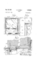
FIGURE 1 is an elevational view of the exterior side of a window embodying the invention.
FIGURE 2 is an elevational view of the interior side of the window.
FIGURE 3 is a fragmentary sectional elevational view of the window and associated structure taken substan tially along line 3-3 of FIGURE 1.
FIGURE 4 is a horizontal sectional elevational view through the window and associated structure with the sash partially raised in order that the section illustrates both the side construction of the sash and the side construction of the fixed glass.
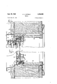
FIGURE 5 is a vertical sectional view of the window and associated structure taken substantially along line 5-5 of FIGURE 1.
FIGURE 6 is a vertical sectional view taken substantially along line 66 of FIGURE 1.
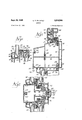
7 FIGURE 7 is a vertical sectional view through another embodiment of the invention showing means for stacking two windows vertically.
FIGURE 8 is a horizontal sectional view through a third embodiment of the invention showing means for connecting two windows side-by-side.
In the embodiment shown in FIGURES 1-6, the window frame is made up of aluminum parts joined together to form a head rail 10, a sill rail 11 a pair of side jamb rails 12. Each of these rails is preferably of extruded aluminum construction and is provided with attaching means for attaching the frame to adjoining portions of the wall. Thus, as shown in FIGURE 3, the head rail has a vertical wind break 13 adapted to be located inwardly of an outside wall member 14 and an outwardly extending web 15 on the exterior of the wall 16.
The head rail is also provided with an inwardly exice tending web 17 substantially coplanar with the outer web 15 provided on its inner end with a pair of parallel flanges 18 and 19 between which is positioned one edge of a wall surface member 28.
Each jamb rail 12, as shown in FIGURE 4, is constructed to have an outside box section 20 of generally rectangular horizontal cross section with this box section including an outwardly extending web 21 and a removable wind break. This removable wind break 22 has a foot flange 23 normally held between spaced brackets 24 and 25 having inturned edges adapted to retain the flange 23. As can be seen in FIGURE 4, the brackets 24 and 25 extend toward each other so that the foot flange 23 may be slid between them longitudinally to attach the wind break 22 in position. The brackets 24 and 25 are integral with an inwardly extending web 26 having on its inner end a pair of parallel flanges 27 adapted to receive one edge of a member 29 similar to the member 28.
The sill rail 11 is also provided with a wind break 30 similar to the wind breaks 13 and 22. The wind break 30 extends downwardly from the main portion 31 of the sill which is of outwardly and downwardly sloped stepped construction. The outer end of this sill is provided with a downward extending flange 32 while the inner end is provided with a pair of depending feet 33 and 34 adapted to rest on the subconstruction 35. The foot 34 is provided with a flange 36 spaced from the inner edge 37 of the rail in order to support one edge of a construction member 38 similar to the members 28 and 29.
As is shown in FIGURE 6, the window is provided with a transverse transom 39 also of aluminum with the transom including an inwardly, upwardly extending portion 40 provided with a forked construction 41 at the top to retain a sealing gasket 42. The transom 39 also has a horizontally outwardly extending portion 43 provided at its outer edge with an upwardly and inwardly extending hook 44.
The transom 39, side jamb webs 21 and head rail web 15 have a fixed window glass 45 located within the frame tormed by these parts. In order to retain the fixed glass 45 in position, there is provided a plastics glazing strip 46. The glazing strip 46 is, of course, on the exterior side of the glass 45 and has a first portion 47 engaging the glass 45 and a second portion 48 engaging the above-described frame formed by the members 15, 21 and 39. This second portion 48 is provided with a hooked end 49 for engaging the hook 44 and similar hooks 50 and 51 on the members 15 and 21, respectively. The first portion 47 of the glazing strip 46 comprises two spaced parts 52 and 53, one of which 53 bears against an edge of the glass 45 and the other of which 52 bears against the side of the glass adjacent the edge. The parts 52 and 53 are distorted away from each other by the glass in order that firm holding pressure is applied to the glass. The two portions 47 and 48 of the strip are distorted toward each other when the glazing strip is in position in order that the resiliency of the plastics strip will apply holding pressure to the glass 45.
The various plastics parts of the window of this invention may of course be made from any weather resistant, solid, resilient plastics described and in a particular embodiment solid polyvinyl chloride is used.
In order to prevent or at least materially inhibit formation of condensate on the interior metal parts of the window in the winter from room air moisture, there are provided various cover members of low heat conductivity substantially entirely covering the interior side of the window. These cover members are joined to the metal members of the window at spaced areas of minor extent with the cover members being otherwise spaced from the metal members to provide heat insulating spaces therebetween. Such spaces maintain the cover members at a relatively warm temperature so that injurious condensate does not form even in the most severe winter weather.
As shown in FIGURE 3 the head rail is provided with a plastics cover member 54 attached to the head rail at only the side edges of the cover member. In the embodiment shown the inner edge of the cover member 54 is provided with a pair of spaced parallel inwardly directed hooked flanges 55 with the hooks extending toward each other and adapted to engage the opposite sides of a headed metal flange 56. The outer edge of the cover member 54 is provided with an inwardly directed hooked flange 57 adapted to be located between a pair of spaced parallel metal flanges 58. The flange construction is such that the cover member 54 itself hides all of the flanges from view and the flanges not only fasten the cover member in place but also space the cover member to provide internal insulating space 59 between the head rail and the cover member.
Because of the insulating effect of the lower sash 60 it is only necessary to provide a relatively simple cover member 61. This cover member is of channel construction and fits over a ribbed flange 62 on the inner end of the sill rail 11.
The side jamb rails 12 are similarly provided with plastics cover members which not only insulate the inner portions of the metal window frame but also provide guideways for the vertically movable sash 60. Thus, as shown in FIGURE 4, the cover member 63 is of right angle construction and arranged substantially parallel to the right angle construction of the web 26 and of the web 64 that forms the inner side of the box section 20. The cover member 63 has one side 65 substantially parallel to the window frame web 26 and is provided with inwardly spaced substantially parallel brackets 66 with inwardly extending spurs engaging the opposite sides of a spurred flange 67 that is formed integrally with the web 26. The opposite side of the cover member 63 is held by means of a web 68 provided with an inwardly directed spur cooperating with a spurred flange 69 that is integral with the side jamb 12.
The inner end of the jamb is provided with its cover member 70 that is attached to the inner end of the jamb web 26 by means of a pair of parallel inwardly spurred cover member flanges 71 engaging similar flanges integral with the web 26 and located between the flanges 71. The cover member 70 and cover member 63 cooperate to provide side guides for the sash 60. Cover member 63 is provided with gaskets '72 and 73 preferably of felt to bear against the side and edge respectively of the sash to seal the sash and frame against penetration by outside weather elements.
The sash 60 includes window glass 74 which like the glass 45 is preferably of the thermal insulating type in which two spaced sheets of glass are joined together at the edges to form an insulating air space therebetween. The glass 74 is provided with a framing 75 enclosing the edges of the glass. This framing is also a plastics material as described above and is constructed of interlocking inner 76 and outer 77 parts that grip the edges of the glass therebetween. As is shown in FIGURE 6 the outer stile part 77 is provided with an inner end 82 that presses against the side of the glass 74. This part 77 is also provided with an outwardly extending flange 78 that makes sealing contact with the gasket 42 on the transom 39 when the window 60 is closed. Extending inwardly of the flange 78 is a hook member 79 having a lower end adapted to make locking engagement with a hook 80 on the outer edge of a flange 81 that extends outwardly from the inner stile part 76. This inner stile part also has an inner end or flange 83 whose edge bears against the inner surface of the glass 74. The hook member 79 on the outer stile part 77 is received between the flange 81 and an outer flange 84 also formed integrally with the outer stile part 77. The outer end of this flange 84- bears against a step 85 on the inner stile part 76 so as to lock the two parts together. The flange ends 82 and 83 are distorted outwardly by their pressure against the sides of the glass 74 from their normal unstressed conditions so as to apply sealing pressure to the sides of the glass.
As can be seen in FIGURE 4, the sides of the framing 75 is substantially the same as the top, as shown in FIG- URE 6, but with the omission of the flange 78. Similarly, as shown in FIGURE 5, the bottom of the framing 75 is substantially the same as the top except for the extension of the inner and outer stile parts into parallel members 86 and 87 with the inner member 87 provided with an integral handle portion 88 and the outer member 86 provided with a pair of spaced inwardly directed arcuate flanges 89 adapted to receive the barbed inner end of a flange member 90 to lock the lower ends of the members 86 and 87 together. This flange member 90 also holds a gasket 91 for sealing against the top surface of the sill rail 11 when the sash 60 is closed. The cover member 61 on the sill rail 11 carries on its outer surface a gasket 120 also preferably of felt similar to the gaskets 72 and 73 and attached in a similar manner.
The inside of the wall 16 surrounding the window is framed by a plastics part 92 for both construction and decorative purposes.
As can be seen from the above description all interior metal parts on the room side of the window are covered by plastics cover members that not only provide a decorative appearance but are also spaced from the metal parts to provide an insulating space therebetween. The insulating effect of the cover members is not exactly understood but it is believed to be more than the mere provision of a dead air space. Observations have indicated that it may be that the cover members absorb heat from the room by radiation and convection and then project this heat by radiation into the air space between the metal and the plastics. This appears to set up a slightly warmer air bubble zone which has a positive internal pressure to prevent the passage or circulation of moisture laden room air. This explanation appears logical because it is noted that with the plastics cover member ice does not form in extremely cold weather on the metal parts that are covered by the cover members even when outside temperatures are many degrees below freezing. Similarly, ice and moisture do not form on the cover members themselves as the cover members are prevented from cooling below the dew point of the atmosphere.
As mentioned above, the cover members are preferably solid polyvinyl chloride. These members cover all metal parts of the frame which is preferably of aluminum that are exposed to the room. In addition, it is preferred that plastics glazing strips be used as described in order to present a pleasing appearance to the exterior.
FIGURE 7 illustrates how this window construction can be used to provide stacked units one on top of the other. In this embodiment a sill rail 11 is located above a head rail 10 and the two are connected together by means of a metal connecting member 93 preferably of extruded aluminum. This connecting member is provided with a horizontal base piece 94 having an outer vertical web 95 and an inner vertical web 96. The upper end of the outer web 95 is provided with a locking groove section 97 receiving the lower end of the outer flange 32 to retain the outer end of the sill rail 11. The upper end of the inner vertical web 96 is provided with inwardly spurred upper and lower parallel flanges 98 for receiving the spurred flange 36. This serves to retain securely the inner end of the sill 11. The center of the sill is supported by providing upwardly extending parallel flanges 99 at an intermediate area with the connecting member 93 embracing the opposite sides of the bottom of the Wind break 30.
The bottom end of the outer vertical web 95 is provided with parallel inwardly extending flanges 100 the lowermost of which is inwardly spurred to retain in position the downwardly extending flange 101 on the outer end of the head rail 10. The bottom of the inner vertical web 96 is provided with inwardly spurred flanges 102 similar to the opposite flanges 98 in order to receive the spurred flange 18 and thereby lock securely the inner end of the head rail 10. This assembly is provided with its plastics cover member 103 that is locked in position at the top by means of an inwardly spurred outwardly extending flange 104 that is received between the upper spurred flange 98 and the inner end 37 of the sill. The lower end of the cover member 103 is provided with a similar outwardly extending spurred flange 105 that is held between the lower spurred flange 102 and the inner end 106 of the head rail 10.
FIGURE 8 discloses an embodiment in which the adjacent side jambs of two adjacent windows may be attached together to form a side-by-side construction. In this embodiment the wind breaks 22 are removed to leave inwardly directed flanges 107. When the two jambs are assembled in side-by-side relationship the two flanges are in contact with each other as shown in FIGURE 8. They are then locked together by means of an inwardly flanged channel member 108 of metal, preferably extruded aluminum. In this side-by-side relationship flanges 27 on the opposite sides of the jambs are similarly in contact with each other and locked together by a channel member 109 like the channel member 108. Then to cover this inner side there is provided a cover member 110 of plastics material having inwardly directed spurred flanges 111 receiving and locked around the channel member 109. The cover member 110 also has sloped side parts ;12 extending toward and contacting the cover members In the various figures used to illustrate the invention it will be noted that for clarity of illustration spaces have been left between certain of the parts. It should be understood, however, that this arrangement is used only for clarity of illustration and in actual practice the spaced parts will actually be in contact with each other.
Having described my invention as related to the embodiment shown in the accompanying drawings, it is my intention that the invention be not limited by any of the details of description, unless otherwise specified, but rather be construed broadly within its spirit and scope as set out in the accompanying claims.
I claim:
1. A window having an exterior side and an interior side, comprising: metal members joined together to form a frame having a head, side jambs, and a sill; a movable sash comprising a glass pane and a rigid plastics stile enclosing the edge of the pane and having side rails, a bottom rail and a top rail; and cover members of low heat conductivity covering the interior side of said frame, said sash moving within and in contact with said cover members to be guided thereby.
2. A window having an exterior side and an interior side, comprising: metal members joined together to form a frame having a head, side jambs and a sill; a movable sash comprising a glass pane and a rigid plastics stile enclosing the edge of the pane and having side rails, a bottom rail and a top rail; and cover members of low heat conductivity covering the interior side of said frame said sash moving within and in contact with said cover members to be guided thereby, certain of said cover members carrying gasket members against which said sash bears.
3. The window of claim 2 wherein means are provided for joining said cover members to said metal members at spaced areas of minor extent with the cover members being otherwise spaced from said metal members to provide heat insulating spaces.
4. A window having an exterior side and an interior side, comprising: metal members joined together to form a frame having a head, side jambs, a sill, and a transom; a movable sash comprising a glass pane and a plastics stile enclosing the edge of the pane and having side rails, a bottom rail and a top check rail carrying an outwardly extending ledge for making sealing engagement with said transom on closing of said sash, said stile including an outer part and an inner part each having a glass bearing portion and an interlocked portion for holding said parts in interlocked relationship; and cover members of low heat conductivity covering the interior side of said frame within which said sash moves, certain of said cover members carrying gasket members against which said sash bears.
5. A window having an exterior side for exposure to outside air and an interior side for exposure to inside air, comprising: metal members joined together to form a frame having a head, side jambs, and a sill; a connecting member joining the head of one frame to the sill of another frame to form a pair of stacked windows, said connecting member having interlocking connections to said head and sill; and a plastics cover strip covering substantially completely the interior sides of said head, sill and connecting member, said cover strip having interlocking connections to said head and said sill.
6. A window having an exterior side and an interior side, comprising: metal members joined together to form a frame having a head, side jambs, and a sill, said side jambs each having removable wind breaks on said exterior sides forming a part thereof; a first connecting member on said interior side joining the jamb of one frame to the jamb of another frame; a second connecting member joining the portions of the exterior sides of said jambs remaining after removal of the wind break on each of said jambs; and plastics cover strips covering the interior side of said jambs and said first connecting member.
7. A window having an exterior side and an interior side, comprising: metal members joined together to form a frame having a head, side jambs, a sill and a transom, said side jambs, head and transom having coplanar glass receiving surfaces on said exterior side; a glass pane having an edge and an outer side and retained against said head, side jamb and transom surfaces to cover the space therebetween; a flexible plastics glazing strip on the exterior side of said glass having a first portion engaging the glass and a second portion engaging said frame with the strip being stressed between said portions to hold the glass in said retained position, said first portion comprising two spaced parts one of which bears against said edge and the other of which bears against said outer side and both of which are thusly stressed to apply pressure against said pane and said second portion being provided with a catch engaging a cooperating catch on said frame to hold said glazing strip and thus said glass in position in the frame; a movable sash comprising a glass pane and a plastics stile enclosing the edge of the pane and having side rails, a bottom rail and a top check rail carrying an outwardly extending ledge for making sealing engagement with said transom on closing of said sash, said stile including an outer part and an inner part each having a glass bearing portion and an interlocked portion for holding said parts in interlocked relationship; plastics cover members of low heat conductivity covering the interior side of said frame within which said sash moves, certain of said cover members carrying gasket members against which said sash bears; and means for joining said cover members to said metal members at spaced areas of minor extent with the cover members being otherwise spaced from said metal members to provide heat insulating spaces,
References Cited by the Examiner UNITED STATES PATENTS Berghoif 2055 Hehr 18975 Toth l8978 Toth 189-75 Fey et a1. 1s9 7s Rasmussen 18975 8 Cipriani et a1. 189-75 Lauer 2056 X Gall 18934 Armstrong 18964 FOREIGN PATENTS Great Britain. Great Britain. Italy.
I HARRISON R. MOSELEY, Primary Examiner.
Claims (1)
1. A WINDOW HAVING AN EXTERIOR SIDE AND AN INTERIOR SIDE, COMPRISING: METAL MEMBERS JOINED TOGETHER TO FORM A FRAME HAVING A HEAD, SIDE JAMBS, AND A SILL; A MOVABLE SASH COMPRISING A GLASS PANE AND A RIGID PLASTICS STILE ENCLOSING THE EDGE OF THE PANE AND HAVING SIDE RAILS, A BOTTOM RAIL AND A TOP RAIL; AND COVER MEMBERS OF LOW HEAT CONDUCTIVITY COVERING THE INTERIOR SIDE OF SAID FRAME, SAID SASH MOVING WITHIN AND IN CONTACT WITH SAID COVER MEMBERS TO BE GUIDED THEREBY.
Priority Applications (1)
| Application Number | Priority Date | Filing Date | Title |
|---|---|---|---|
| US205646A US3208564A (en) | 1962-06-27 | 1962-06-27 | Window |
Applications Claiming Priority (1)
| Application Number | Priority Date | Filing Date | Title |
|---|---|---|---|
| US205646A US3208564A (en) | 1962-06-27 | 1962-06-27 | Window |
Publications (1)
| Publication Number | Publication Date |
|---|---|
| US3208564A true US3208564A (en) | 1965-09-28 |
Family
ID=22763056
Family Applications (1)
| Application Number | Title | Priority Date | Filing Date |
|---|---|---|---|
| US205646A Expired - Lifetime US3208564A (en) | 1962-06-27 | 1962-06-27 | Window |
Country Status (1)
| Country | Link |
|---|---|
| US (1) | US3208564A (en) |
Cited By (26)
| Publication number | Priority date | Publication date | Assignee | Title |
|---|---|---|---|---|
| US3323262A (en) * | 1964-12-10 | 1967-06-06 | Nat Gypsum Co | Z-bar frame assembly |
| US3363390A (en) * | 1966-04-25 | 1968-01-16 | Crane Plastics Inc | Extruded plastic panel-framing strip having integral rigid body section and resiliently flexible panel-gripping flanges |
| US3364645A (en) * | 1965-02-18 | 1968-01-23 | Alliancewall Corp | Door construction |
| US3416271A (en) * | 1967-08-04 | 1968-12-17 | Robert F. Heeney | Metal window frame construction with liner board channel |
| US3705002A (en) * | 1969-08-06 | 1972-12-05 | Giovanni Varlonga | Bearing sections for the covering with marble plates, panels and the like of walls both uninterrupted and interrupted by doors, windows and the like |
| US3771582A (en) * | 1972-02-18 | 1973-11-13 | R Hairston | Self-flashing louver |
| US4411111A (en) * | 1979-11-13 | 1983-10-25 | Yoshida Kogyo K. K. | Window sash assembly |
| US4437266A (en) | 1980-03-21 | 1984-03-20 | Keller Wilbur L | Weatherstripping kit for sliding windows |
| US4569154A (en) * | 1983-11-28 | 1986-02-11 | Thermal-Barrier Products, Inc. | Thermally insulating window assembly |
| US4756135A (en) * | 1987-05-11 | 1988-07-12 | Joseph Citrullo | Window frame assembly |
| US5007219A (en) * | 1988-02-11 | 1991-04-16 | 501 Thermal Profiles, Inc. | Round top window |
| USD333357S (en) | 1992-07-09 | 1993-02-16 | Apco Graphics, Inc. | Door extrusion |
| US5456054A (en) * | 1993-04-29 | 1995-10-10 | Coupet; Jean-Marie | Section bar having an elastically deformable branch for covering the edge of a panel or of a first section bar, a frame element and a door implementing said section bars |
| US5619828A (en) * | 1994-12-19 | 1997-04-15 | Pella Corporation | Installation fin for windows and doors |
| US5924255A (en) * | 1998-01-16 | 1999-07-20 | Richwood Building Products, Inc. | Shutter assembly |
| US5987826A (en) * | 1997-10-08 | 1999-11-23 | Alpa Lumber Inc. | Window assembly |
| US6125599A (en) * | 1998-08-19 | 2000-10-03 | Durable Products Company, Inc. | Door sill with flanges for attachment to jambs |
| US6173541B1 (en) * | 1997-10-09 | 2001-01-16 | Alpa Lumber Inc. | Window assembly |
| CH691616A5 (en) * | 1996-12-23 | 2001-08-31 | Dfs Technology & Service Ag | Plastic window and method for its production. |
| CH691615A5 (en) * | 1996-12-23 | 2001-08-31 | Dfs Technology & Service Ag | Plastic window and method for its production. |
| US20050115174A1 (en) * | 2002-10-25 | 2005-06-02 | Hubert Elmer | Separating wall |
| US20050144861A1 (en) * | 2003-03-27 | 2005-07-07 | Gabriel Petta | Frame assembly for windows or doors |
| US20060059780A1 (en) * | 2004-09-20 | 2006-03-23 | Gabriel Petta | Frame assembly for window with vertically sliding sash |
| US20060086052A1 (en) * | 2004-10-22 | 2006-04-27 | Gabriel Petta | Slider window with continuous seals |
| US20080104892A1 (en) * | 2006-11-04 | 2008-05-08 | Deceuninck North America, Llc | Window assembly with sash frame interlocking system to resist wind load and impact |
| US20190169918A1 (en) * | 2010-06-03 | 2019-06-06 | Perfect Window Reveal, Llc | Window reveal systems and methods |
Citations (12)
| Publication number | Priority date | Publication date | Assignee | Title |
|---|---|---|---|---|
| US2456486A (en) * | 1946-01-02 | 1948-12-14 | B J Company Inc | Inside storm window |
| US2701041A (en) * | 1945-11-08 | 1955-02-01 | Toth Louis | Windowpane retainer |
| US2711232A (en) * | 1947-05-15 | 1955-06-21 | Toth Louis | Weather tight window construction |
| GB771181A (en) * | 1955-08-30 | 1957-03-27 | Myrtha Gotthard | Improvements relating to frames for display or other windows |
| US2795306A (en) * | 1953-10-07 | 1957-06-11 | Hehr Mfg Company | Window structure |
| US2840202A (en) * | 1956-09-05 | 1958-06-24 | Elmer T Hehr | Window fastener construction |
| GB818142A (en) * | 1954-10-20 | 1959-08-12 | Michael F Robertshaw Ltd | Improvements in or relating to casement windows |
| US2927355A (en) * | 1955-09-22 | 1960-03-08 | Rasmussen & Co V K | Glass face consisting of framed units comprising one or more layers of glass |
| US2996845A (en) * | 1958-09-11 | 1961-08-22 | Kimble Glass Co | Structural panel and building wall construction utilizing same |
| US2999279A (en) * | 1957-07-22 | 1961-09-12 | Falako Corp | Window structure |
| US3071215A (en) * | 1957-04-17 | 1963-01-01 | George R Gall | Curtain wall |
| US3080023A (en) * | 1960-02-15 | 1963-03-05 | Armstrong Henry Paul | Windows |
-
1962
- 1962-06-27 US US205646A patent/US3208564A/en not_active Expired - Lifetime
Patent Citations (12)
| Publication number | Priority date | Publication date | Assignee | Title |
|---|---|---|---|---|
| US2701041A (en) * | 1945-11-08 | 1955-02-01 | Toth Louis | Windowpane retainer |
| US2456486A (en) * | 1946-01-02 | 1948-12-14 | B J Company Inc | Inside storm window |
| US2711232A (en) * | 1947-05-15 | 1955-06-21 | Toth Louis | Weather tight window construction |
| US2795306A (en) * | 1953-10-07 | 1957-06-11 | Hehr Mfg Company | Window structure |
| GB818142A (en) * | 1954-10-20 | 1959-08-12 | Michael F Robertshaw Ltd | Improvements in or relating to casement windows |
| GB771181A (en) * | 1955-08-30 | 1957-03-27 | Myrtha Gotthard | Improvements relating to frames for display or other windows |
| US2927355A (en) * | 1955-09-22 | 1960-03-08 | Rasmussen & Co V K | Glass face consisting of framed units comprising one or more layers of glass |
| US2840202A (en) * | 1956-09-05 | 1958-06-24 | Elmer T Hehr | Window fastener construction |
| US3071215A (en) * | 1957-04-17 | 1963-01-01 | George R Gall | Curtain wall |
| US2999279A (en) * | 1957-07-22 | 1961-09-12 | Falako Corp | Window structure |
| US2996845A (en) * | 1958-09-11 | 1961-08-22 | Kimble Glass Co | Structural panel and building wall construction utilizing same |
| US3080023A (en) * | 1960-02-15 | 1963-03-05 | Armstrong Henry Paul | Windows |
Cited By (29)
| Publication number | Priority date | Publication date | Assignee | Title |
|---|---|---|---|---|
| US3323262A (en) * | 1964-12-10 | 1967-06-06 | Nat Gypsum Co | Z-bar frame assembly |
| US3364645A (en) * | 1965-02-18 | 1968-01-23 | Alliancewall Corp | Door construction |
| US3363390A (en) * | 1966-04-25 | 1968-01-16 | Crane Plastics Inc | Extruded plastic panel-framing strip having integral rigid body section and resiliently flexible panel-gripping flanges |
| US3416271A (en) * | 1967-08-04 | 1968-12-17 | Robert F. Heeney | Metal window frame construction with liner board channel |
| US3705002A (en) * | 1969-08-06 | 1972-12-05 | Giovanni Varlonga | Bearing sections for the covering with marble plates, panels and the like of walls both uninterrupted and interrupted by doors, windows and the like |
| US3771582A (en) * | 1972-02-18 | 1973-11-13 | R Hairston | Self-flashing louver |
| US4411111A (en) * | 1979-11-13 | 1983-10-25 | Yoshida Kogyo K. K. | Window sash assembly |
| US4437266A (en) | 1980-03-21 | 1984-03-20 | Keller Wilbur L | Weatherstripping kit for sliding windows |
| US4569154A (en) * | 1983-11-28 | 1986-02-11 | Thermal-Barrier Products, Inc. | Thermally insulating window assembly |
| US4756135A (en) * | 1987-05-11 | 1988-07-12 | Joseph Citrullo | Window frame assembly |
| US5007219A (en) * | 1988-02-11 | 1991-04-16 | 501 Thermal Profiles, Inc. | Round top window |
| USD333357S (en) | 1992-07-09 | 1993-02-16 | Apco Graphics, Inc. | Door extrusion |
| US5456054A (en) * | 1993-04-29 | 1995-10-10 | Coupet; Jean-Marie | Section bar having an elastically deformable branch for covering the edge of a panel or of a first section bar, a frame element and a door implementing said section bars |
| US5619828A (en) * | 1994-12-19 | 1997-04-15 | Pella Corporation | Installation fin for windows and doors |
| CH691616A5 (en) * | 1996-12-23 | 2001-08-31 | Dfs Technology & Service Ag | Plastic window and method for its production. |
| CH691615A5 (en) * | 1996-12-23 | 2001-08-31 | Dfs Technology & Service Ag | Plastic window and method for its production. |
| US5987826A (en) * | 1997-10-08 | 1999-11-23 | Alpa Lumber Inc. | Window assembly |
| US6173541B1 (en) * | 1997-10-09 | 2001-01-16 | Alpa Lumber Inc. | Window assembly |
| US5924255A (en) * | 1998-01-16 | 1999-07-20 | Richwood Building Products, Inc. | Shutter assembly |
| US6125599A (en) * | 1998-08-19 | 2000-10-03 | Durable Products Company, Inc. | Door sill with flanges for attachment to jambs |
| US20050115174A1 (en) * | 2002-10-25 | 2005-06-02 | Hubert Elmer | Separating wall |
| US20050144861A1 (en) * | 2003-03-27 | 2005-07-07 | Gabriel Petta | Frame assembly for windows or doors |
| US7707778B2 (en) | 2003-03-27 | 2010-05-04 | Alpa Lumber Inc. | Frame assembly for windows or doors with removable sash |
| US20060059780A1 (en) * | 2004-09-20 | 2006-03-23 | Gabriel Petta | Frame assembly for window with vertically sliding sash |
| US7707779B2 (en) | 2004-09-20 | 2010-05-04 | Alpa Lumber Inc. | Frame assembly for window with vertically sliding sash |
| US20060086052A1 (en) * | 2004-10-22 | 2006-04-27 | Gabriel Petta | Slider window with continuous seals |
| US20080104892A1 (en) * | 2006-11-04 | 2008-05-08 | Deceuninck North America, Llc | Window assembly with sash frame interlocking system to resist wind load and impact |
| US7827734B2 (en) * | 2006-11-04 | 2010-11-09 | Deceuninck North America, Llc | Window assembly with sash frame interlocking system to resist wind load and impact |
| US20190169918A1 (en) * | 2010-06-03 | 2019-06-06 | Perfect Window Reveal, Llc | Window reveal systems and methods |
Similar Documents
| Publication | Publication Date | Title |
|---|---|---|
| US3208564A (en) | Window | |
| US3383801A (en) | Window | |
| US4207717A (en) | System for improving heat insulating characteristics of existing curtain walls and the like | |
| US4399636A (en) | Thermal insulated doorsill apparatus with insulating spacer fastener | |
| US4299060A (en) | Insulated door and window construction | |
| US3918231A (en) | Frost resistant window sash | |
| US4554770A (en) | Horizontal sliding window with removable fixed sash | |
| US4488387A (en) | Sliding door weather-sealing device and assembly | |
| US3427775A (en) | Insulated structural barrier | |
| US3530618A (en) | Composite door and window construction | |
| US3896589A (en) | Thermally improved window frame and sash | |
| US4027431A (en) | Single hung window with removable fixed lite | |
| US4611447A (en) | Curtain wall and window frame construction | |
| KR101672855B1 (en) | Durable curtain wall windows and doors | |
| US2768410A (en) | Expansible storm sash | |
| US4309845A (en) | Thermally insulated hinged windows and doors | |
| US4199900A (en) | Storm window unit | |
| US3190411A (en) | Window and door structural element | |
| GB2055937A (en) | An insulating frame assembly for a window or glazed door | |
| US2654920A (en) | Insulated metal window closure | |
| US4120127A (en) | Double glazed wall structure | |
| US2151231A (en) | Window construction | |
| US2257123A (en) | Window construction | |
| US3332184A (en) | Thermal insulators for metal door and window frames | |
| KR101368355B1 (en) | High-efficiency energy-saving curtain wall |
Legal Events
| Date | Code | Title | Description |
|---|---|---|---|
| AS | Assignment |
Owner name: CARADCO CORPORATION, 201 EVANS RD. RANTOUL, ILL. 6 Free format text: ASSIGNMENT OF ASSIGNORS INTEREST.;ASSIGNOR:BENDIX INTERNATIONAL FINANCE CORPORATION;REEL/FRAME:003961/0585 Effective date: 19820401 Owner name: BENDIX INTERNATIONAL FINANCE CORPORATION A CORP. O Free format text: MERGER;ASSIGNOR:BENDIX FOREST PRODUCTS CORPORATION;REEL/FRAME:003961/0578 Effective date: 19810225 |