US2729381A - Process and devices for the submitting successively of bottles and other receptacles to exhaustion and pressure - Google Patents
Process and devices for the submitting successively of bottles and other receptacles to exhaustion and pressure Download PDFInfo
- Publication number
- US2729381A US2729381A US276214A US27621452A US2729381A US 2729381 A US2729381 A US 2729381A US 276214 A US276214 A US 276214A US 27621452 A US27621452 A US 27621452A US 2729381 A US2729381 A US 2729381A
- Authority
- US
- United States
- Prior art keywords
- receptacle
- cap
- pressure
- orifice
- closure
- Prior art date
- Legal status (The legal status is an assumption and is not a legal conclusion. Google has not performed a legal analysis and makes no representation as to the accuracy of the status listed.)
- Expired - Lifetime
Links
- 238000000034 method Methods 0.000 title description 19
- 239000012530 fluid Substances 0.000 description 12
- 208000016253 exhaustion Diseases 0.000 description 8
- 239000007788 liquid Substances 0.000 description 2
- 101100345589 Mus musculus Mical1 gene Proteins 0.000 description 1
- 206010038743 Restlessness Diseases 0.000 description 1
- BVKZGUZCCUSVTD-UHFFFAOYSA-N carbonic acid Chemical compound OC(O)=O BVKZGUZCCUSVTD-UHFFFAOYSA-N 0.000 description 1
- 230000000694 effects Effects 0.000 description 1
- 239000000463 material Substances 0.000 description 1
- 229920003052 natural elastomer Polymers 0.000 description 1
- 229920001194 natural rubber Polymers 0.000 description 1
- 239000000126 substance Substances 0.000 description 1
- 229920003051 synthetic elastomer Polymers 0.000 description 1
- 239000005061 synthetic rubber Substances 0.000 description 1
Images

Classifications
-
- B—PERFORMING OPERATIONS; TRANSPORTING
- B65—CONVEYING; PACKING; STORING; HANDLING THIN OR FILAMENTARY MATERIAL
- B65D—CONTAINERS FOR STORAGE OR TRANSPORT OF ARTICLES OR MATERIALS, e.g. BAGS, BARRELS, BOTTLES, BOXES, CANS, CARTONS, CRATES, DRUMS, JARS, TANKS, HOPPERS, FORWARDING CONTAINERS; ACCESSORIES, CLOSURES, OR FITTINGS THEREFOR; PACKAGING ELEMENTS; PACKAGES
- B65D51/00—Closures not otherwise provided for
- B65D51/16—Closures not otherwise provided for with means for venting air or gas
-
- B—PERFORMING OPERATIONS; TRANSPORTING
- B67—OPENING, CLOSING OR CLEANING BOTTLES, JARS OR SIMILAR CONTAINERS; LIQUID HANDLING
- B67B—APPLYING CLOSURE MEMBERS TO BOTTLES JARS, OR SIMILAR CONTAINERS; OPENING CLOSED CONTAINERS
- B67B3/00—Closing bottles, jars or similar containers by applying caps
Definitions
- the invention relates to a process for submitting, with the help of a known type of closure or obturator and by the use of a suitable device, a receptacle successively to exhaustion and to pressure.
- the type of closure permitting the application of such a said process principally consists of a cap of rigid material which has at least one orifice and a diaphragm in said cap having at least one.
- the cap is preferably of the crown type and the diaphragm made of an element of natural or synthetic rubber.
- the object of the process is above all the ability to draw out of the receptacles into which e. g. carbonic acid is to be introduced, the air confined in the free space between the liquid and the closure. It may, in fact, be judged essential to protect completely the liquid from any contact with the air, especially with a view to im proving its conservation.
- closures permittingthe lowering or increasing of the pressure of the receptacle are such that only one of these two operations can be taken into account, the second being excluded by reason of the very structure of the closure.
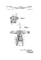
- Figures 5, 6 and 7 show, in a vertical section, the three characteristic positions of a device according to the invention.
- Figure 8 represents, in a vertical section, a variant of the device, object of the invention.
- Figure 9 is a section according to the line 1X'--IX of the Figure 8.
- Figures 10 and 11 show, in a vertical section, forms of execution of the pusher rod.
- the process consists in employing a closure formed by the combination of a cap 1 having, for example, a central hole 2 and a dia-' phragm 3 with, for example, an eccentric hole 4.
- the closure thus arranged is applied, for example, to a receptacle in the usual way.
- the first phase of the process consists, as shown in Figure 2, in mechanically urging the elastic diaphragm 3, for example by the action of a needle 6 passed through the central orifice 2 of the cap 1, and thus separating the said cap from the said diaphragm, which opens holes 2 and 4.
- the second phase of the process consists in bringing the receptacle in communication with an exhaust pump, the air confined in the receptacle being able to escape normally through the said holes 4 and 2.
- the third phase illustrated in Figure 3 consists in bringing the receptacle into relation with a source of fluid under pressure, while the mechanical urging of the diaphragm 3 is or is not maintained.
- the last phase consists in completely releasing the receptacle so that, owing to the interior pressure in the receptacle, the diaphragm 3 is ice firmly pressed against the cap 1 properly so called, and r cylindrical chamber 9 in which the upper part of the receptacle and closure therefor are received.
- a thin rod 10 is placed, the length of which is, such that, when the device is in position, the free end of the said rod pushes back the elastic diaphragm of the closure.
- the bottom of the cylindrical chamber 9 shows orifices 11 which terminate in a chamber 12, which itself is extended by a channel 13 in a threeways-valve 14.
- In the body of this valve end are two conduits, one of which, 15 is connected with an exhaustpump (not shown) and the other 16 communicates with a source of fluid under pressure (not shown).
- the device In normal position, the device is as is represented in Figure 5, that is to say, the valve properly so called shuts the two conduits 15 16.
- the pusher rod 10 automatically and gently pushes back the elastic diaphragm 3. It is therefore enough to work the valve 14 in order to bring it to v the position represented in Figure 6, which putsthe receptacle into direct communication with the exhaust pump. Then, without displacing the device, but by worka of the fluid under pressure, the valve being then in the position shown in Figure 7.
- the pusher rod 10 is fixed. It may be deemed useful, in certain applications, to shield the thin rod 10, and to have it ready to be placed into the active position during the phases of the submission of the receptacle to a decrease and increase of the pressure.
- Figures 8 and 9 show such an arrangement, the active position of the rod 10 being determined by the placing into the active position of the valve 14.
- the rod '10 is positively guided in the axis of the bottom 17 and of a second bottom 18 and terminates in the body of the valve 14.
- This rod 10 is provided with a transversal stop 19 andis'urged into the inactive position by a return spring 20.
- the chest 21 of the valve has a groove 22 of suitable profile, into which the corresponding end of the said thin rod '10 may penetrate. This groove 22 is arranged in such a way that when the said valve is in the closed position, the said rod 10 is normally shielded.
- the withdrawal of the rod might also be allowed immediately after the closing of the passagefto'wards the exhaust-pump, since the mechanical urging of theela'stic diaphragm 3 is superfluous 'durin'gthe' phase "of 'sub'r'riission to pressure.
- the invention extends to all the devices generally of any sort, capable of urging mechanically and temporaril the elastic diaphragm of a closure with a view tofreeirig the orifices, respectively of the 'cap' and of the'said elastic diaphragm and to putting the receptacle into'coni'r'riunication, successively, with an exhaustump and a generator or a source of fluid under pressure.
- the pusher rod may have the form (if a"simple spindle of a hard substance or, as shown in Fi'g'ure'lO, the end Needless'to say that the difierent phases of the process of the invention might be applied by independent devices used in "succession, the diaphragm being, for exair'iple,
- a process for the submitting successively t'o exhaus tion and pressure of receptacles closed by a closure oft'h'e type that comprises a cap the bott'oihof which has at least one orifice and against this bottom an elastic diaphragm having at least one orifice not juxtaposed to the orifice of the said cap, said process'comprising' thesteps' of: applying a 'force by which the elastic diaphragm is mechanically urged so that the orifice of the'cap 'isteri'iporarily freed and the orifice of the diaphragm is ternporarily opened, connecting the interior of the receptacle with a source of vacuum while 'said rnecha'nical urging of the diaphragm is maintained, then connecting the iiiterior 'of said receptacle to a source of a fluid under'pre'ssure.
- a process for the submitting successively to exhaustion and pressure of receptacles closed by a closure-of the type that comprises a cap the bottom of which has at least one orifice and against this bottom an elastic diaphragm having at least one orifice not juxtaposed to the orifice of the said cap, said process comprising the steps of: applying a force by which the elastic diaphragm is me'-' chanically urged by a pushing effect in such a way that'the said diaphragm is slightly removed from the cap so that the orifice of the cap is temporarily freed and the orifice of the diaphragm is temporarily opened, connecting the interior of the receptacle with a source of vacuum while the said mechanical urging of the diaphragm is maintained, and then connecting the interior of said receptacle to a source of a fluid under pressure.
- a device for successively exhausting and filling under pressure within a receptacle, in combination with an apertured closure having an elastic diaphragm therein for said receptacle said device comprising a hood capable of being placed on the apertured closure of the receptacle; at least one pusher in said hood capable of going through the cap and of pushing back the elastic diaphragm when the said hood is placed on the said cap; means in said hood affording a controlled communication with an exhaust apparatus and means affording .a controlled communication with a source of fluid under pressure.
- a device for successively exhausting and filling under pressure within a receptacle in combination with a closure having an elastic diaphragm for said receptacle, said device comprising a hood having a conical mouth extended by a chamber fitting the form and the dimensions of the closure for said receptacle, a pusher in the axis of said chamber capable of going through the closure and of pushing back the elastic diaphragm therein, the said hood having controllable means for communication, on the one hand, with an exhaust apparatus and, on the other hand, with a source of fluid under pressure.
- Apparatus for the submitting successively to exhaustion and pressure filling of receptacles in combination with a closure for said receptacles of the type that comprises a cap, the bottom of which has at least one orifice and against this bottom an elastic diaphragm having a t least one orifice not juxtaposed to the orifice of said cap, said apparatus comprising a hood capable of being applied to the closure of the receptacle, a pusher in said hood fixed with regard to the hood but of such form and-of such dimensions that by the mere placing of the said hood on the closure, the said pusher goes through the said orifice of the closure and pushes the elastic diaphragm back to a predetermined extent, means in said hood providing a controlled connection With an exhaust apparatus and a controlled connection with a source of fluid under pressure.
Landscapes
- Engineering & Computer Science (AREA)
- Mechanical Engineering (AREA)
- Reciprocating Pumps (AREA)
Description
3, 1956 J. N. WISER 2,729,381
7 PROCESS AND DEVICES FOR THE SUBMITTING SUCCESSIVELY OF BOTTLES AND OTHER RECEPTACLES T0 EXHAUSTION AND PRESSURE 2 Sheets-Sheet 1 Filed March 12, 1952 Penw ATTORNE YJ' Jac ues N. h 'sec/m mrak 'Jan. 3, 1956 J. N. WISER 2,729,381
ES FOR THE PROCESS AND DE SUBMITTING SU SSIVELY OF BOT S AND OTHER RECEPTACLES EXHAUSTION AND PRESSURE Filed March 12, 1952 2 Sheets-Sheet 2' Jacques N, HL'sey vy rap United States Patent 2,729,381 I PROCESS AND DEVICES FOR THE SUBMITTING SUCCESSIVELY OF BO'ITLES AND OTHER RE- CEPTACLES TO EXHAUSTION AND PRESSURE Jacques Nicolas Wiser, Antwerp, Belgium Application March 12, 1952, Serial No. 276,214 6 Claims. (31. 226-116) The invention relates to a process for submitting, with the help of a known type of closure or obturator and by the use of a suitable device, a receptacle successively to exhaustion and to pressure. The type of closure permitting the application of such a said process principally consists of a cap of rigid material which has at least one orifice and a diaphragm in said cap having at least one.
orifice remote from said first named orifice. The cap is preferably of the crown type and the diaphragm made of an element of natural or synthetic rubber.
The object of the process is above all the ability to draw out of the receptacles into which e. g. carbonic acid is to be introduced, the air confined in the free space between the liquid and the closure. It may, in fact, be judged essential to protect completely the liquid from any contact with the air, especially with a view to im proving its conservation. J
In a general way, closures permittingthe lowering or increasing of the pressure of the receptacle are such that only one of these two operations can be taken into account, the second being excluded by reason of the very structure of the closure.
n the contrary, the process of this invention, admits of the successive application of the two operations.
The process and characteristic devices are described more particularly below, with references to the annexed drawings, in which 1 Figures 1 to 4 diagrammatize the successive phases of the process, object of the invention;
Figures 5, 6 and 7 show, in a vertical section, the three characteristic positions of a device according to the invention;
Figure 8 represents, in a vertical section, a variant of the device, object of the invention; s
Figure 9 is a section according to the line 1X'--IX of the Figure 8;
Figures 10 and 11 show, in a vertical section, forms of execution of the pusher rod.
As illustrated in Figures 1 to 4, the process consists in employing a closure formed by the combination of a cap 1 having, for example, a central hole 2 and a dia-' phragm 3 with, for example, an eccentric hole 4. The closure thus arranged is applied, for example, to a receptacle in the usual way. The first phase of the process consists, as shown in Figure 2, in mechanically urging the elastic diaphragm 3, for example by the action of a needle 6 passed through the central orifice 2 of the cap 1, and thus separating the said cap from the said diaphragm, which opens holes 2 and 4. The second phase of the process consists in bringing the receptacle in communication with an exhaust pump, the air confined in the receptacle being able to escape normally through the said holes 4 and 2. The third phase illustrated in Figure 3 consists in bringing the receptacle into relation with a source of fluid under pressure, while the mechanical urging of the diaphragm 3 is or is not maintained. Finally, the last phase consists in completely releasing the receptacle so that, owing to the interior pressure in the receptacle, the diaphragm 3 is ice firmly pressed against the cap 1 properly so called, and r cylindrical chamber 9 in which the upper part of the receptacle and closure therefor are received.
In the axis of the head 7 a thin rod 10 is placed, the length of which is, such that, when the device is in position, the free end of the said rod pushes back the elastic diaphragm of the closure. The bottom of the cylindrical chamber 9 shows orifices 11 which terminate in a chamber 12, which itself is extended by a channel 13 in a threeways-valve 14. In the body of this valve end are two conduits, one of which, 15 is connected with an exhaustpump (not shown) and the other 16 communicates with a source of fluid under pressure (not shown).
In normal position, the device is as is represented in Figure 5, that is to say, the valve properly so called shuts the two conduits 15 16. When this device is placed on the receptacle, the pusher rod 10 automatically and gently pushes back the elastic diaphragm 3. It is therefore enough to work the valve 14 in order to bring it to v the position represented in Figure 6, which putsthe receptacle into direct communication with the exhaust pump. Then, without displacing the device, but by worka of the fluid under pressure, the valve being then in the position shown in Figure 7. When the submission. to-
pressure is ended, it is enough either to remove the device or to take away the receptacle.
In this execution, the pusher rod 10 is fixed. It may be deemed useful, in certain applications, to shield the thin rod 10, and to have it ready to be placed into the active position during the phases of the submission of the receptacle to a decrease and increase of the pressure.
Figures 8 and 9 show such an arrangement, the active position of the rod 10 being determined by the placing into the active position of the valve 14. In this 'execution, the rod '10 is positively guided in the axis of the bottom 17 and of a second bottom 18 and terminates in the body of the valve 14. This rod 10 is provided with a transversal stop 19 andis'urged into the inactive position by a return spring 20. v The chest 21 of the valve has a groove 22 of suitable profile, into which the corresponding end of the said thin rod '10 may penetrate. This groove 22 is arranged in such a way that when the said valve is in the closed position, the said rod 10 is normally shielded. The result is that when the device is not in use, the rod 10 is completely shielded, as shown in Figure 8. In this position, the device may be normally applied to the-receptacle. Thus, on the valve being turned to bring it into the position that puts the receptacle intocommunication with the exhaust-pump by means of the conduit 15," the=chest 21 pushes the rod 10 back, by acting against the return-spring 20, and, during'this manoeuvre,'the said rod progressively penetrates the cap 1 while pushing back the elastic diaphragm 3. When the valve is quite open in this position, the rod 10 is exactly in place. In a way, the first and second phases have been realized at the same time. When the valve is manoeuvred to interrupt the exhaust-pump and to connect the receptacle with the feeder of the fluid under pressure, by means of the conduit 16, the rod 10 remains stationary. It will immediately be shielded when the valve is again in the closed position, the groove 22 then placing itself in front of the corresponding end of the rod 10, which, acted upon by Patented Jan. 3, 1956 unrest the-return-spring "20, will show a rapid backwardmovement.
The withdrawal of the rod might also be allowed immediately after the closing of the passagefto'wards the exhaust-pump, since the mechanical urging of theela'stic diaphragm 3 is superfluous 'durin'gthe' phase "of 'sub'r'riission to pressure.
Still other numerous variants may be adopted within the range of the present invention, and, in a generalway, the invention extends to all the devices generally of any sort, capable of urging mechanically and temporaril the elastic diaphragm of a closure with a view tofreeirig the orifices, respectively of the 'cap' and of the'said elastic diaphragm and to putting the receptacle into'coni'r'riunication, successively, with an exhaustump and a generator or a source of fluid under pressure.
The pusher rod may have the form (if a"simple spindle of a hard substance or, as shown in Fi'g'ure'lO, the end Needless'to say that the difierent phases of the process of the invention might be applied by independent devices used in "succession, the diaphragm being, for exair'iple,
temporarily removed by an individual means separate from the device for the connection of the receptacle with the exhaust-pump, or the source of the fluid under pressure.
What I- claim is:
l. A process for the submitting successively t'o exhaus tion and pressure of receptacles closed by a closure oft'h'e type that comprises a cap the bott'oihof which has at least one orifice and against this bottom an elastic diaphragm having at least one orifice not juxtaposed to the orifice of the said cap, said process'comprising' thesteps' of: applying a 'force by which the elastic diaphragm is mechanically urged so that the orifice of the'cap 'isteri'iporarily freed and the orifice of the diaphragm is ternporarily opened, connecting the interior of the receptacle with a source of vacuum while 'said rnecha'nical urging of the diaphragm is maintained, then connecting the iiiterior 'of said receptacle to a source of a fluid under'pre'ssure.
2. A process for the submitting successively to exhaustion and pressure of receptacles closed by a closure-of the type that comprises a cap the bottom of which has at least one orifice and against this bottom an elastic diaphragm having at least one orifice not juxtaposed to the orifice of the said cap, said process comprising the steps of: applying a force by which the elastic diaphragm is me'-' chanically urged by a pushing effect in such a way that'the said diaphragm is slightly removed from the cap so that the orifice of the cap is temporarily freed and the orifice of the diaphragm is temporarily opened, connecting the interior of the receptacle with a source of vacuum while the said mechanical urging of the diaphragm is maintained, and then connecting the interior of said receptacle to a source of a fluid under pressure.
3. A process-for thesubmittingsuccessively to exhaustion and pressure of receptacles closed by a closure of the type that comprises a cap the bottom of which has at least one orifice and against this bottom an elastic diaphragm having at least one orifice not juxtaposed to the orifice of the said cap, said process comprising the steps of: applying a force by which the elastic diaphragm is pushed back by a pusher that goes through the cap so that the orifice of the cap is temporarily freed and the orifice of the diaphragm is temporarily opened, connecting the interior of the receptacle with a source of vacuum while the said mechanical urging of the diaphragm is maintained, and then connecting the interior of said receptacle with a source of a fluid under pressure.
4. A device for successively exhausting and filling under pressure within a receptacle, in combination with an apertured closure having an elastic diaphragm therein for said receptacle, said device comprising a hood capable of being placed on the apertured closure of the receptacle; at least one pusher in said hood capable of going through the cap and of pushing back the elastic diaphragm when the said hood is placed on the said cap; means in said hood affording a controlled communication with an exhaust apparatus and means affording .a controlled communication with a source of fluid under pressure.
5. A device for successively exhausting and filling under pressure Within a receptacle, in combination with a closure having an elastic diaphragm for said receptacle, said device comprising a hood having a conical mouth extended by a chamber fitting the form and the dimensions of the closure for said receptacle, a pusher in the axis of said chamber capable of going through the closure and of pushing back the elastic diaphragm therein, the said hood having controllable means for communication, on the one hand, with an exhaust apparatus and, on the other hand, with a source of fluid under pressure.
6. Apparatus for the submitting successively to exhaustion and pressure filling of receptacles, in combination with a closure for said receptacles of the type that comprises a cap, the bottom of which has at least one orifice and against this bottom an elastic diaphragm having a t least one orifice not juxtaposed to the orifice of said cap, said apparatus comprising a hood capable of being applied to the closure of the receptacle, a pusher in said hood fixed with regard to the hood but of such form and-of such dimensions that by the mere placing of the said hood on the closure, the said pusher goes through the said orifice of the closure and pushes the elastic diaphragm back to a predetermined extent, means in said hood providing a controlled connection With an exhaust apparatus and a controlled connection with a source of fluid under pressure.
References Cited in the tile of this patent UNITED STATES PATENTS 1,392,189 McColl a; a1. Apr. 29, 1919 2,518,064 Rapisarda Aug. 8, 1950 2,564,163 Lep'erre Aug. 14, 1951 2,684,805 McBean Iuly 27, 1954
Priority Applications (1)
| Application Number | Priority Date | Filing Date | Title |
|---|---|---|---|
| US276214A US2729381A (en) | 1952-03-12 | 1952-03-12 | Process and devices for the submitting successively of bottles and other receptacles to exhaustion and pressure |
Applications Claiming Priority (1)
| Application Number | Priority Date | Filing Date | Title |
|---|---|---|---|
| US276214A US2729381A (en) | 1952-03-12 | 1952-03-12 | Process and devices for the submitting successively of bottles and other receptacles to exhaustion and pressure |
Publications (1)
| Publication Number | Publication Date |
|---|---|
| US2729381A true US2729381A (en) | 1956-01-03 |
Family
ID=23055675
Family Applications (1)
| Application Number | Title | Priority Date | Filing Date |
|---|---|---|---|
| US276214A Expired - Lifetime US2729381A (en) | 1952-03-12 | 1952-03-12 | Process and devices for the submitting successively of bottles and other receptacles to exhaustion and pressure |
Country Status (1)
| Country | Link |
|---|---|
| US (1) | US2729381A (en) |
Cited By (11)
| Publication number | Priority date | Publication date | Assignee | Title |
|---|---|---|---|---|
| US3688812A (en) * | 1971-02-17 | 1972-09-05 | Oceanography Intern Corp | Method for sealing ampoules |
| US4114866A (en) * | 1976-06-19 | 1978-09-19 | Tokico Ltd. | Gas filling arrangement for a telescopic suspension unit |
| US4763803A (en) * | 1986-01-20 | 1988-08-16 | Schneider Bernardus J J A | Stopper for a container such as a bottle, and a pump connectable thereto for extraction of gaseous medium from or pumping in thereof into the container |
| US4947650A (en) * | 1989-09-08 | 1990-08-14 | Vacuum Barrier Corporation | Method and apparatus for liquid cryogen pressurization of containers of particulates |
| DE3939783A1 (en) * | 1989-12-01 | 1991-06-06 | Henri Haist | DEEP-TURNED LOCKING CAP FROM ALUMINUM FOR GLASS BOTTLES UNDER PRESSURE AND THERMOFLOWING DEVICE FOR A LOCKING HEAD FOR THE PRODUCTION OF SUCH LATHE CAPS |
| US5031785A (en) * | 1990-02-14 | 1991-07-16 | Epicurean International Corp. | Combination vacuum/pressure pump and valve stopper for food or drink containers |
| US5215129A (en) * | 1990-09-28 | 1993-06-01 | Bermar International Limited | Preserving the contents of beverage containers |
| US20050061393A1 (en) * | 2003-08-21 | 2005-03-24 | Armando Luis | Wine preservation system using a central vaccum |
| US20060102659A1 (en) * | 2002-09-04 | 2006-05-18 | Marr David T | Method and apparatus for preserving the contents of beverage containers |
| US20120031927A1 (en) * | 2009-02-13 | 2012-02-09 | Eurocave Sa | Apparatus for pouring a liquid into a glass in particular wine |
| US20140216265A1 (en) * | 2009-06-17 | 2014-08-07 | Jose Luis Godoy Varo | Installation for Customizing Alcoholic Drinks and Fragrances |
Citations (4)
| Publication number | Priority date | Publication date | Assignee | Title |
|---|---|---|---|---|
| US1302189A (en) * | 1917-09-01 | 1919-04-29 | Thermokept Products Corp | Method of canning and can. |
| US2518064A (en) * | 1946-06-22 | 1950-08-08 | Gilbert & Barker Mfg Co | Can filling machine |
| US2564163A (en) * | 1943-01-12 | 1951-08-14 | Leperre Jean Emile Lucien | Receptacle with elastic bag insert and system for filling and emptying the same |
| US2684805A (en) * | 1950-08-09 | 1954-07-27 | Carter Prod Inc | Method for charging liquid products and volatile propellants into pressure-tight containers |
-
1952
- 1952-03-12 US US276214A patent/US2729381A/en not_active Expired - Lifetime
Patent Citations (4)
| Publication number | Priority date | Publication date | Assignee | Title |
|---|---|---|---|---|
| US1302189A (en) * | 1917-09-01 | 1919-04-29 | Thermokept Products Corp | Method of canning and can. |
| US2564163A (en) * | 1943-01-12 | 1951-08-14 | Leperre Jean Emile Lucien | Receptacle with elastic bag insert and system for filling and emptying the same |
| US2518064A (en) * | 1946-06-22 | 1950-08-08 | Gilbert & Barker Mfg Co | Can filling machine |
| US2684805A (en) * | 1950-08-09 | 1954-07-27 | Carter Prod Inc | Method for charging liquid products and volatile propellants into pressure-tight containers |
Cited By (17)
| Publication number | Priority date | Publication date | Assignee | Title |
|---|---|---|---|---|
| US3688812A (en) * | 1971-02-17 | 1972-09-05 | Oceanography Intern Corp | Method for sealing ampoules |
| US4114866A (en) * | 1976-06-19 | 1978-09-19 | Tokico Ltd. | Gas filling arrangement for a telescopic suspension unit |
| US4763803A (en) * | 1986-01-20 | 1988-08-16 | Schneider Bernardus J J A | Stopper for a container such as a bottle, and a pump connectable thereto for extraction of gaseous medium from or pumping in thereof into the container |
| US4911314A (en) * | 1986-01-20 | 1990-03-27 | Schneider Bernardus J J A | Stopper for a container such as a bottle, and a pump connectable thereto for extraction of gaseous medium from or pumping in thereof into the container |
| US4947650A (en) * | 1989-09-08 | 1990-08-14 | Vacuum Barrier Corporation | Method and apparatus for liquid cryogen pressurization of containers of particulates |
| DE3939783A1 (en) * | 1989-12-01 | 1991-06-06 | Henri Haist | DEEP-TURNED LOCKING CAP FROM ALUMINUM FOR GLASS BOTTLES UNDER PRESSURE AND THERMOFLOWING DEVICE FOR A LOCKING HEAD FOR THE PRODUCTION OF SUCH LATHE CAPS |
| US5031785A (en) * | 1990-02-14 | 1991-07-16 | Epicurean International Corp. | Combination vacuum/pressure pump and valve stopper for food or drink containers |
| US5215129A (en) * | 1990-09-28 | 1993-06-01 | Bermar International Limited | Preserving the contents of beverage containers |
| US20060102659A1 (en) * | 2002-09-04 | 2006-05-18 | Marr David T | Method and apparatus for preserving the contents of beverage containers |
| US6886605B2 (en) | 2003-08-21 | 2005-05-03 | Armando Luis | Wine preservation system using a central vacuum |
| US20050161108A1 (en) * | 2003-08-21 | 2005-07-28 | Armando Luis | Wine preservation system using a central vacuum |
| US20050161109A1 (en) * | 2003-08-21 | 2005-07-28 | Armando Luis | Wine preservation system using a central vacuum |
| US20050061393A1 (en) * | 2003-08-21 | 2005-03-24 | Armando Luis | Wine preservation system using a central vaccum |
| US7048016B2 (en) * | 2003-08-21 | 2006-05-23 | Armando Luis | Wine preservation system using a central vacuum |
| US7108023B2 (en) | 2003-08-21 | 2006-09-19 | Armando Luis | Wine preservation system using a central vacuum |
| US20120031927A1 (en) * | 2009-02-13 | 2012-02-09 | Eurocave Sa | Apparatus for pouring a liquid into a glass in particular wine |
| US20140216265A1 (en) * | 2009-06-17 | 2014-08-07 | Jose Luis Godoy Varo | Installation for Customizing Alcoholic Drinks and Fragrances |
Similar Documents
| Publication | Publication Date | Title |
|---|---|---|
| US2729381A (en) | Process and devices for the submitting successively of bottles and other receptacles to exhaustion and pressure | |
| US3032037A (en) | Means for the extraction and storage of blood | |
| US2393578A (en) | Closure | |
| GB1128323A (en) | Sterilising and filling bottles | |
| DE3372085D1 (en) | Apparatus and method for filling a container, especially aseptic filling | |
| DK150842B (en) | BLOOD SAMPLING DEVICE | |
| GB938617A (en) | Non-refillable infuser or container and method of using same | |
| GB1512685A (en) | Capillary vessel for collecting blood | |
| US2743047A (en) | Process of and apparatus for the filling of containers | |
| US4129130A (en) | Vial-syringe | |
| US2832344A (en) | Blood sample collector | |
| US1893716A (en) | Filling, vacuumizing, sterilizing, and sealing machine | |
| GB1504057A (en) | Infusion and transfusion apparatus | |
| AU474316B2 (en) | Process and device for opening a sealing element which cannot be actuated, ofthe bottom nozzle ofa casting vessel | |
| GB1206023A (en) | Package forming methods and apparatus | |
| GB1005947A (en) | Improvements in or relating to apparatus for closing containers | |
| GB1270277A (en) | Improvements in container filling apparatus and methods | |
| US1766918A (en) | Hypodermic syringe for injecting liquids into the body or for taking them therefrom | |
| IE41770L (en) | Dispensing device. | |
| GB959128A (en) | Improvements in or relating to inflation apparatus | |
| US2393491A (en) | Canning device | |
| GB1349154A (en) | Apparatus for filling containers with liquid | |
| GB477388A (en) | Means for removing foil seals or caps from the mouths of bottles and like containers | |
| US1980417A (en) | Art of canning | |
| GB673281A (en) | Device for facilitating the removal, by means of an injection syringe, of injection solution from a container |