US2677832A - Convertible bed - Google Patents
Convertible bed Download PDFInfo
- Publication number
- US2677832A US2677832A US246624A US24662451A US2677832A US 2677832 A US2677832 A US 2677832A US 246624 A US246624 A US 246624A US 24662451 A US24662451 A US 24662451A US 2677832 A US2677832 A US 2677832A
- Authority
- US
- United States
- Prior art keywords
- bed
- frames
- frame
- spring
- rail
- Prior art date
- Legal status (The legal status is an assumption and is not a legal conclusion. Google has not performed a legal analysis and makes no representation as to the accuracy of the status listed.)
- Expired - Lifetime
Links
- 238000006243 chemical reaction Methods 0.000 description 27
- 238000010276 construction Methods 0.000 description 18
- 210000002105 tongue Anatomy 0.000 description 9
- 230000015572 biosynthetic process Effects 0.000 description 2
- 230000000295 complement effect Effects 0.000 description 2
- 241000180579 Arca Species 0.000 description 1
- 101100102516 Clonostachys rogersoniana vern gene Proteins 0.000 description 1
- 238000003197 gene knockdown Methods 0.000 description 1
- 238000004519 manufacturing process Methods 0.000 description 1
Images


Classifications
-
- A—HUMAN NECESSITIES
- A47—FURNITURE; DOMESTIC ARTICLES OR APPLIANCES; COFFEE MILLS; SPICE MILLS; SUCTION CLEANERS IN GENERAL
- A47D—FURNITURE SPECIALLY ADAPTED FOR CHILDREN
- A47D7/00—Children's beds
- A47D7/01—Children's beds with adjustable parts, e.g. for adapting the length to the growth of the children
-
- A—HUMAN NECESSITIES
- A47—FURNITURE; DOMESTIC ARTICLES OR APPLIANCES; COFFEE MILLS; SPICE MILLS; SUCTION CLEANERS IN GENERAL
- A47D—FURNITURE SPECIALLY ADAPTED FOR CHILDREN
- A47D11/00—Children's furniture convertible into other kinds of furniture, e.g. children's chairs or benches convertible into beds or constructional play-furniture
- A47D11/005—Convertible children's beds
-
- A—HUMAN NECESSITIES
- A47—FURNITURE; DOMESTIC ARTICLES OR APPLIANCES; COFFEE MILLS; SPICE MILLS; SUCTION CLEANERS IN GENERAL
- A47D—FURNITURE SPECIALLY ADAPTED FOR CHILDREN
- A47D9/00—Cradles ; Bassinets
- A47D9/008—Cradles ; Bassinets dismountable
-
- A—HUMAN NECESSITIES
- A47—FURNITURE; DOMESTIC ARTICLES OR APPLIANCES; COFFEE MILLS; SPICE MILLS; SUCTION CLEANERS IN GENERAL
- A47D—FURNITURE SPECIALLY ADAPTED FOR CHILDREN
- A47D9/00—Cradles ; Bassinets
- A47D9/012—Cradles ; Bassinets with adjustable parts
Definitions
- This invention relates to bed construction. More particularly, the invention has reference to a bed convertible into a bassinette, a baby bed or crib, a junior bed, and a youth bed respectively.
- Beds of various types and sizes have been .devised for use by children. However, except perhaps to a limited extent, these have not been convertible. As a result, it is customary to purchase, at different stages during a childs growth, a bassinette, a baby bed or crib, a youth bed, a junior bed, and a conventional bed, in the order named. Oftentimes, due to the expense involved, one or more of these is dispensed with, with an attendant sacrifice in the comfort and safety of the child.
- a bed construction be devised that will be so designed at to permit use thereof initially as a bassinette, after which, at different stages during the childs growth, the bed can he convertible successively to a crib, youth bed, junior bed, and in many instances, a conventional bed having no side guards or the like.
- Another important object is to provide a convertible bed as described which can be sold at relatively low cost, considering the fact that the bed is usable for accommodating a child from infancy.
- Another important object is to provide a bed as stated, wherein the conversions can be effected with ease by the purchaser, whenever desired.
- Still another important object is to provide a hed of the type stated which, in each of the forms to which it is converted, will be attractive in appearance and eilicient in respect to the manner .in which it discharges its intended functions.
- Yet another object is to provide, in a bed of the character described, a spring construction wherein a pair of spring frames are separably but rigidly connectible to one another, to increase the overall length of the bed spring embodied in the bed, each of said spring frames being usable independently of one another, in different forms to which the bed is converted.
- Still another important object is to provide a spring construction wherein the mattress-supporting portion of the spring, that is mounted upon the spring frame, is novelly designed in a manner to provide a particularly effective support for the mattress, while yet affording full comfort to the user, said mattress-supporting Serial No. 246,624
- portion of the bed spring being novelly designed .to impart thereto the characteristic of rugged- ⁇ ness and eiiciency in object is to provide out the several views,
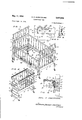
- Figure 1 is a perspective view of one form to which the structure constituting the present invention is convertible, said form comprising a baby bed or crib, the mattress-supporting portion of the spring being shown fragmentarily;
- Figure 2 is a perspective view of a bassinette conversion form
- Figure 3 is a perspective view of a junior bed
- Figure 4 is a perspective view of a youth bed
- Figure 5 is a detail sectional view taken substantially on line 5-5 of Figure 1, showing a means embodied in the invention for holding the slidable bed guard of the crib illustrated in Figure 1 in elevated position;
- Figure 6 is an enlarged detail sectional view, taken on line 6 6 of to one of the end frames;
- Figure 7 is a detail sectional view, taken on the line l-l of Figure 6;
- Figure 8 is an enlarged detail sectional view taken on line 8-8 of Figure 4, showing the means whereby the spring frames are rigidly connected to one another;
- Figure 9 is a detail sectional View, on an enlarged scale, taken on the line 9 9 of Figure 4 and illustrating the means for attaching one of the conversion frames to its associated end frame;
- Figure 10 is a perspective view of a large spring frame formed in accordance with the present invention.
- Figure 1l is a perspective view of a smaller spring frame, formed in accordance with the present invention.
- Figure 12 is an enlarged fragmentary plan View of the spring frame of Figure and Figure 13 is a fragmentary perspective view illustratingl the spring frames of Figures l0 and 1l as they appear when rigidly connected to one another to extend the overall length of the spring.
- Figures l, 2, 3, and 4 show different types of beds which can be constructed, using component parts of the invention. Considering these in the order in which they would be normally used during the growth of a child, reference should nrst be had to Figure 2.
- each end frame IEE includes a horizontally extended top rail l2, extending from side to side o1 the frame, and arranged in spaced, parallel relation to a bottom rail i4.
- the top rail l2 and the bottom rail I4 are integrally or otherwise rigidly connected to vertically extended side rails i8, that extend downwardly below the bottom rail ill, to provide a pair of vertical, parallel legs, which can be equipped with casters or the like if desired.
- a longitudinal tongue i6 Formed on the top surface of the top rail l2, and extending fully from end to end of said top rail, is a longitudinal tongue i6.
- the purpose of the tongue IS will be explained in detaii hereinafter, in the description of the baby bed or crib illustrated in Figure l.
- the end frames ld When assembled to provide the bassinette illustrated in Figure 2, the end frames ld are spaced apart rather closely, through tervening conversion frames, generally designated 2li, and formed in the present instance as open rectangular frame members slatted in the manner referred to above in the description of the end frames i2, through the provision of parallel slats 22.
- the conversion frames 2li are vertically disposed, extending between opposite ends of the respective end frames I9, and are set on end. Then, opposite sides of the conversion frames are fixedly connected to the end fra-mes associated therewith, through the provision of a connecting means shown in detail in Figure 9.
- This connecting means includes a female bolt 2li, interiorly threaded to receive the threaded male bolt 26, said bolts extending between registering openings formed in the conversion and end frames, so as to separably but rigidly connect the frames.
- bolts 24 and 26 each have flat ornamental heads, and are usable either verticallyT or horizontally to connect, for example, frame iii to 2li, or frame 25 to a spring frame 32 to be described hereinafter.
- the end and conversion frames are of equal thickness throughout, so far as the material of their component parts is concerned.
- a small spring frame generally designated 28, and illustrated in Figure 11, is used.
- the construction of the spring frame the provision of in- 228 will be covered in detail hereinafter, but it will suffice to state at this time that the spring frame is of rectangular outer connguration, and is proportioned to fit snugly in the rectangular space enclosed by the coacting end frames l0 and conversion frames 20.
- the end frames are connected directly to opposite sides of the spring frame 28, said end frames being provided with brackets to be described hereinafter, that have tongues to which the spring frame is bolted, so that the completed bassinette conversion form is possessed of a high degree of rigidity and strength, while yet being small and compact in size, so as to accommodate with comfort a newly born infant.
- FIG. l there is illustrated a baby bed or crib, and in assembling the baby bed, a larger spring frame generally designated 3Q is used, instead of the frame 28.
- the opposite ends of the spring frame 3G are bolted directly to the end frames l0, said opposite ends of the frame 3D being bolted to the aforementioned tongues, and the conversion frames 28 are positioned directly7 upon the top edges of the end frames.
- the conversion frames 2G are each formed, along one longitudinal edge thereof, with a groove complementary to the 'tongue it, so as to interengage the top rail l2 of each end frame it with one side of the conversion frame.
- the cooperating male and female bolts 2t, 24 are extended through registering openings formed in the conversion frames and end frames respectively, to secure the frames rigidly but separably to one another in superposed relation, while in a common vertical plane.
- guide rods 32 are secured at their upper ends to the conversion frames, at one side of the baby bed or crib.
- the guide rods S2 are of inverted L-shaped formation, having short laterally extended legs at their upper ends, which preferably have threaded male ends engaged by female bolts such as the bolts 24.
- the guide rods 32 are connected to laterally extended angle brackets 36, that are screwed to the lower end portions of the legs of the end frames ill.
- the guide rods Prior to connecting the guide rods to the conversion frames, the guide rods are passed through vertically aligned openings formed in opposite ends of a bed guard 3, of elongated, rectangular configuration.
- the bed guard 36 is oi vertically slatted construction, so as to be in harmony with the conversion and end frames.
- the bed guard 34 When slidably adjusted downwardly upon the guide rod 32, the bed guard 34 is engaged by the brackets 36, to limit downward movement thereof. Obviously, it is desirable that the bed guards be held in a raised position, when slid upwardly upon the guide rods, so as to be aligned horizontally with a fixed side frame 38 extending along the opposite side of the baby bed or crib, and bolted through the medium of the male and female bolts described above, to the end frames ill.
- I provide a construction particularly well shown in Figure 5.
- Spaced longitudinally of the lower longitudinal edge of the bed guard 34 are angle brackets 40, secured to the inner surface of the bed guard, and extending laterally in the general direction of the spring frame 30.
- a pair of hinges 42 is provided upon the adjacent side of the spring frame 30, each of said hinges having an upper hinge member bolted rigidly ybut separably to the spring frame, and a free swinging lower hinge member having a slot 44 proportioned to receive a laterally extended portion of the associated angle bracket 40.
- an elongated connecting bar 45 extending between the hinges e2, in parallelism with the adjacent side of the spring frame 36.
- the bar it is bolted or otherwise rigidly connected to the swinging portions of the hinges, and thus, when the bar l5 is swung inwardly, the hinges are positioned to receive the laterally projected portions of the brackets 40, thus to hold the bed guard 32 in raised position.
- the user again swing the bar 46 inwardly, so as to -disengage the brackets 4i) and permit the bed guard to gravitate to its lower position.
- FIG. 3 there is here illustrated a junior bed, such as is often used when the child has grown beyond the crib stage, but is still believed to be too young to use a conventional bed having no side guards.
- a junior bed such as is often used when the child has grown beyond the crib stage, but is still believed to be too young to use a conventional bed having no side guards.
- the conversion frames After the conversion frames have been so removed, they are secured in the positions illustrated in Figure 3. In these positions, the conversion frames abut at one end against one of the end frames I0, and are secured to said end frame by means of coacting male and female bolts 25, 2li. Similar bolts are used to connect the lower longitudinal edges of the conversion frames directly to the opposite side rails of the spring frame 30, said side rails of the spring frame being designated 48 and being integral or otherwise rigid at one end with a transversely extended head rail 50.
- FIG. 4 there is here illustrated a youth bed, which is similar in most respects to the junior bed illustrated in Figure 3, except for being substantially longer. It is advisable to convert from a junior bed to a youth bed as the child grows, so as to provide a bed suiciently long to accommodate the growing child, while still providing the desired protection against the childs falling out of the bed while sleeping.
- the spring frame 3U is provided at one end with a movable foot rail 52.
- the foot rail 52 is elevated until it is in the same plane as the fixed head rail 50, the foot rail being illustrated in this position in Figure 10.
- the overall length of the bed spring must be increased, and it is advisable to lower the foot rail 52 relative to the remaining parts of the spring frame 30, and connect it rigidly in its lower position to a cooperating foot rail formed to substantially the same length as the foot rail 52.
- the cooperating foot rail is mounted upon the bed frame 28.
- the bed frame 28, though smaller in size than the frame 30, is of the same general construction, having parallel side rails 5i rigid at one end with a transversely disposed end rail 55.
- the other end rail 58 of the frame 2t is, in one position thereof, secured to the adjacent ends of the side rails 54, in a plane common with the end rail 56. However, in another position of the rail 58, said rail is lowered as illustrated in Figure 8.
- the openings in said rails are brought into registry with the lower pair of openings 55 of the plates 5d, and bolts are extended through the registering openings to secure the rails 52 and 58 in their lowered positions.
- the securing bolts in this connection, pass not only through the plates 5i?, but through both of the rails 52 and 58, so as to not only rigidly connect the side rails of the spring frames to one another in end to end relation, but also to connect the dropped rails 52 and 55 with complete rigidity.
- the plate 65 receives the laterally extended tongue of an angle bracket 55, having a depending leg provided with four countersunk openings 61 through which screws 59 extend, said screws extending into the inner Surface of the bottom rail Ill of the end frame.
- Said laterally extended tongue of the angle bracket S3 extends through the slot 62 of the plate Eil, which slot registers with a longitudinal slot formed in the rail 52 or 58, as the case may be, when said rail 52 or 58 is elevated to its upper position.
- Bolts are used to connect the laterally extended tongue of the bracket 6B directly to the rails 50 or 52 (on spring frame Sil) or to rails 5S or 58 (on spring frame 2B) as the case may be, said rails 5G and 52, or 55 and 55 having bolt-receiving openings coinciding with the boltreceiving openings of the bracket tongues.
- Each rail of the spring frames 30 and 28 is provided with openings receiving the outer ends of elongated coil springs 15, the ends of said coil springs 10 being hooked through the openings and the springs being arranged in parallel relation, extending longitudinally of the spring frame in which they are mounted.
- Shorter transverse springs 12 are hooked at one end through openings formed in the side rails of the respective spring frames.
- V-shaped end links lil of stout wire material are engaged intermediate their ends with the inner ends oi the spring li).
- the ends oi said V-shapcd end links ar hooked into small, flat plates '16, each of which is orrned with a plurality of openings arranged in a marginal series upon said plates.
- intermediate links I8 extend longitudinally or the respective spring frames, and connect longitudinally spaced, adjacent plates 18.
- Each intermediate link 13 is formed from a single length of wire material, having hook-shaped ends, and a pair of intermediate line extends between each pair of longitudinally spaced plates 16.
- Transverse links 8E are each formed of a single length of material having hook-shaped ends, and are disposed transversely of the spring frame, so as to connect the plates 'i8 in transversely spaced relation.
- the conversion can, in each case, be effected by the purchaser with substantial ease and facility, and without the use of special tools.
- Male and female bolts previously used in holding in rigid relationship component parts of the bed when it is in one form, can be removed and used in assembling component parts oi the bed when another form is being constructed.
- many of the parts of the structure are capable oi use in different positions, reference being here made to the conversion frames 20 which in the bassinette form provide elongated, narrow sides, provide upper extensions of the end frames in the crib form, and provide side guards in the youth and junior bed forms.
- a bed spring a pair of elongated, parallel side rails; an end rail iixedly connected at opposite ends to one end of the side rails and disposed coplanar to said side rails; a second end rail extending between the other ends of the side rails; means for securing the second end rail to said side rails in selected positions of elevation in one of which it is coplanar with the first-named end rail, and in the other or" which it is at a level below the plane of said lfirst-named end rail; a plurality of plates arranged in intersecting transverse and longitudinal rows between the respective side rails and end rails; straight links connecting the plates of said transverse and parallel rows; coil springs extending inwardly toward the plates from the side and end rails, those springs extending inwardly from the side rails being connected directly to the plates of the outermost longitudinal rows; and V-shaped links extending from those coil springs extending from the end rails and con nected to the plates
- said first recnngular frame embodying a pair of parallel rails, an end rail iixedly connected at opposite ends to one end of said side rails and disposed coplanar to said side rails, and a second end rail extending between the other ends of said side rails and morably connected to the side rails in selected positions of elevation in one of which it is ,y nar with said Iirst named end rail and in the otl ci which it is at a level below the plane of said :first end rail; said extension frame embodying pair ci parallel side rails, a rst end rail fixedly connected at opposite ends to one end ci said last named side rails, a second end rail tending between the other ends of said last named side rails and movably connected to the side rails positions of elevation in one of which i coplanar with .s
- a bed spring comprising a rst rectangular frame and an extension frame also of rectangular configuration but smaller in size than the irst rectangular frame and projecting from said rst rectangular frame in end to end relation, said rst rectangular frame embodying a pair of parallel side rails, an end rail xedly connected at opposite ends to one end of said side rails and disposed coplanar to said side rails, and a second end rail extending between the other ends of said side rails and movably connected to the side rails in selected positions of elevation in one of which it is coplanar with said rst named end rail and in the other of which it is at a level below the plane of said first end rail; said extension frame embodying a pair of parallel side rails, a rst end rail xedly connected at opposite ends to one end of said last named side rails, a second end rail extending bepositions of elevation in one of which it is coplanar with said last named end rail and in the said last
Landscapes
- Invalid Beds And Related Equipment (AREA)
Description
May 11, 1954 E. c. cHRlsTl-:NSEN
CONVERTIBLE BED 3 Sheets-Sheet l Filed Sept. 14, 1951 m/ ZW mM il, MM
flmw/ f m F V 6 I. al Ill'- ATTORNEYS May 1l, 1954 E. c. cHRlsTENsEN CONVERTIBLE BED 3 Sheets-Sheet 2 Filed Sept. 14, 1951 ATTORNEYS Patented May 1l, 1954 CONVERTIBLE BED Emil C. Christensen, Burlington, Iowa Application September 14, 1951,
3 Claims.
This invention relates to bed construction. More particularly, the invention has reference to a bed convertible into a bassinette, a baby bed or crib, a junior bed, and a youth bed respectively.
Beds of various types and sizes have been .devised for use by children. However, except perhaps to a limited extent, these have not been convertible. As a result, it is customary to purchase, at different stages during a childs growth, a bassinette, a baby bed or crib, a youth bed, a junior bed, and a conventional bed, in the order named. Oftentimes, due to the expense involved, one or more of these is dispensed with, with an attendant sacrifice in the comfort and safety of the child.
In view of the above, it is believed to be clearly desirable that a bed construction be devised that will be so designed at to permit use thereof initially as a bassinette, after which, at different stages during the childs growth, the bed can he convertible successively to a crib, youth bed, junior bed, and in many instances, a conventional bed having no side guards or the like.
It is the main object of the present invention to provide a bed construction convertible in this manner.
Another important object is to provide a convertible bed as described which can be sold at relatively low cost, considering the fact that the bed is usable for accommodating a child from infancy.
Another important object is to provide a bed as stated, wherein the conversions can be effected with ease by the purchaser, whenever desired.
Still another important object is to provide a hed of the type stated which, in each of the forms to which it is converted, will be attractive in appearance and eilicient in respect to the manner .in which it discharges its intended functions.
Yet another object is to provide, in a bed of the character described, a spring construction wherein a pair of spring frames are separably but rigidly connectible to one another, to increase the overall length of the bed spring embodied in the bed, each of said spring frames being usable independently of one another, in different forms to which the bed is converted.
Still another important object is to provide a spring construction wherein the mattress-supporting portion of the spring, that is mounted upon the spring frame, is novelly designed in a manner to provide a particularly effective support for the mattress, while yet affording full comfort to the user, said mattress-supporting Serial No. 246,624
portion of the bed spring being novelly designed .to impart thereto the characteristic of rugged- `ness and eiiciency in object is to provide out the several views,
Figure 1 is a perspective view of one form to which the structure constituting the present invention is convertible, said form comprising a baby bed or crib, the mattress-supporting portion of the spring being shown fragmentarily;
Figure 2 is a perspective view of a bassinette conversion form;
Figure 3 is a perspective view of a junior bed;
Figure 4 is a perspective view of a youth bed;
Figure 5 is a detail sectional view taken substantially on line 5-5 of Figure 1, showing a means embodied in the invention for holding the slidable bed guard of the crib illustrated in Figure 1 in elevated position;
Figure 6 is an enlarged detail sectional view, taken on line 6 6 of to one of the end frames;
Figure 7 is a detail sectional view, taken on the line l-l of Figure 6;
Figure 8 is an enlarged detail sectional view taken on line 8-8 of Figure 4, showing the means whereby the spring frames are rigidly connected to one another;
Figure 9 is a detail sectional View, on an enlarged scale, taken on the line 9 9 of Figure 4 and illustrating the means for attaching one of the conversion frames to its associated end frame;
Figure 10 is a perspective view of a large spring frame formed in accordance with the present invention;
Figure 1l is a perspective view of a smaller spring frame, formed in accordance with the present invention;
Figure 12 is an enlarged fragmentary plan View of the spring frame of Figure and Figure 13 is a fragmentary perspective view illustratingl the spring frames of Figures l0 and 1l as they appear when rigidly connected to one another to extend the overall length of the spring.
Referring to the drawings in detail, Figures l, 2, 3, and 4 show different types of beds which can be constructed, using component parts of the invention. Considering these in the order in which they would be normally used during the growth of a child, reference should nrst be had to Figure 2.
in Figure 2, there is illustrated a bassinette which includes a pair of end frames generally designated ill. rThe end frames i are disposed in vertical planes, and are formed with rectangular upper portions formed as open frames. rEhe upper portion of each end frame IEE includes a horizontally extended top rail l2, extending from side to side o1 the frame, and arranged in spaced, parallel relation to a bottom rail i4. At their opposite ends, the top rail l2 and the bottom rail I4 are integrally or otherwise rigidly connected to vertically extended side rails i8, that extend downwardly below the bottom rail ill, to provide a pair of vertical, parallel legs, which can be equipped with casters or the like if desired.
Formed on the top surface of the top rail l2, and extending fully from end to end of said top rail, is a longitudinal tongue i6. The purpose of the tongue IS will be explained in detaii hereinafter, in the description of the baby bed or crib illustrated in Figure l.
Extending between the top and bottom rails, and spaced longitudinally of said rails, are vern tically extended, parallel slats le. Obviously, the particular configuration of the slats could be varied as desired, and in fact, if desired the open rectangular upper frame portions of the end frame lil can be solidly formed, rather than formed with the slats i9.
When assembled to provide the bassinette illustrated in Figure 2, the end frames ld are spaced apart rather closely, through tervening conversion frames, generally designated 2li, and formed in the present instance as open rectangular frame members slatted in the manner referred to above in the description of the end frames i2, through the provision of parallel slats 22.
In assembling the bassinette, the conversion frames 2li are vertically disposed, extending between opposite ends of the respective end frames I9, and are set on end. Then, opposite sides of the conversion frames are fixedly connected to the end fra-mes associated therewith, through the provision of a connecting means shown in detail in Figure 9. This connecting means includes a female bolt 2li, interiorly threaded to receive the threaded male bolt 26, said bolts extending between registering openings formed in the conversion and end frames, so as to separably but rigidly connect the frames. In this connection, bolts 24 and 26 each have flat ornamental heads, and are usable either verticallyT or horizontally to connect, for example, frame iii to 2li, or frame 25 to a spring frame 32 to be described hereinafter. The end and conversion frames, it should be noted, are of equal thickness throughout, so far as the material of their component parts is concerned.
In forming the bassinette, a small spring frame generally designated 28, and illustrated in Figure 11, is used. The construction of the spring frame the provision of in- 228 will be covered in detail hereinafter, but it will suffice to state at this time that the spring frame is of rectangular outer connguration, and is proportioned to fit snugly in the rectangular space denned by the coacting end frames l0 and conversion frames 20. The end frames are connected directly to opposite sides of the spring frame 28, said end frames being provided with brackets to be described hereinafter, that have tongues to which the spring frame is bolted, so that the completed bassinette conversion form is possessed of a high degree of rigidity and strength, while yet being small and compact in size, so as to accommodate with comfort a newly born infant.
In Figure l there is illustrated a baby bed or crib, and in assembling the baby bed, a larger spring frame generally designated 3Q is used, instead of the frame 28. The opposite ends of the spring frame 3G are bolted directly to the end frames l0, said opposite ends of the frame 3D being bolted to the aforementioned tongues, and the conversion frames 28 are positioned directly7 upon the top edges of the end frames. In this connection, the conversion frames 2G are each formed, along one longitudinal edge thereof, with a groove complementary to the 'tongue it, so as to interengage the top rail l2 of each end frame it with one side of the conversion frame. rlhereafter, the cooperating male and female bolts 2t, 24 are extended through registering openings formed in the conversion frames and end frames respectively, to secure the frames rigidly but separably to one another in superposed relation, while in a common vertical plane.
After the conversion frames have been attached to the top edges of the end frames in the manner illustrated in Figure l, guide rods 32 are secured at their upper ends to the conversion frames, at one side of the baby bed or crib. The guide rods S2 are of inverted L-shaped formation, having short laterally extended legs at their upper ends, which preferably have threaded male ends engaged by female bolts such as the bolts 24. At their lower ends, the guide rods 32 are connected to laterally extended angle brackets 36, that are screwed to the lower end portions of the legs of the end frames ill.
Prior to connecting the guide rods to the conversion frames, the guide rods are passed through vertically aligned openings formed in opposite ends of a bed guard 3, of elongated, rectangular configuration. Preferably, the bed guard 36 is oi vertically slatted construction, so as to be in harmony with the conversion and end frames.
When slidably adjusted downwardly upon the guide rod 32, the bed guard 34 is engaged by the brackets 36, to limit downward movement thereof. Obviously, it is desirable that the bed guards be held in a raised position, when slid upwardly upon the guide rods, so as to be aligned horizontally with a fixed side frame 38 extending along the opposite side of the baby bed or crib, and bolted through the medium of the male and female bolts described above, to the end frames ill.
As a means for holding the bed guard 34 in raised position, I provide a construction particularly well shown in Figure 5. Spaced longitudinally of the lower longitudinal edge of the bed guard 34 are angle brackets 40, secured to the inner surface of the bed guard, and extending laterally in the general direction of the spring frame 30. A pair of hinges 42 is provided upon the adjacent side of the spring frame 30, each of said hinges having an upper hinge member bolted rigidly ybut separably to the spring frame, and a free swinging lower hinge member having a slot 44 proportioned to receive a laterally extended portion of the associated angle bracket 40.
For joint operation of the swinging portions of the hinges 42, there is provided an elongated connecting bar 45 extending between the hinges e2, in parallelism with the adjacent side of the spring frame 36. At its opposite ends, the bar it is bolted or otherwise rigidly connected to the swinging portions of the hinges, and thus, when the bar l5 is swung inwardly, the hinges are positioned to receive the laterally projected portions of the brackets 40, thus to hold the bed guard 32 in raised position. Obviously, to lower the bed guard, it is necessary merely that the user again swing the bar 46 inwardly, so as to -disengage the brackets 4i) and permit the bed guard to gravitate to its lower position.
lt is believed suiciently obvious as not to require special illustration that coil springs, not shown, can be provided upon the lower ends of the guide rods 32, to cushion the fall of the bed guard.
Referring now to Figure 3. there is here illustrated a junior bed, such as is often used when the child has grown beyond the crib stage, but is still believed to be too young to use a conventional bed having no side guards. To form the junior bed from the baby bed or crib illustrated in Figure 1, it is necessary merely to remove the conversion frames :from their position above the end frames IFJ, and dispense with the side frame 38, the bed guard 34, the guide rods 32, and the means described immediately above attachable to the spring frame 30 for the purpose of holding the bed guard in elevated position.
After the conversion frames have been so removed, they are secured in the positions illustrated in Figure 3. In these positions, the conversion frames abut at one end against one of the end frames I0, and are secured to said end frame by means of coacting male and female bolts 25, 2li. Similar bolts are used to connect the lower longitudinal edges of the conversion frames directly to the opposite side rails of the spring frame 30, said side rails of the spring frame being designated 48 and being integral or otherwise rigid at one end with a transversely extended head rail 50.
1n this way, a junior bed is formed which provides ample protection against the childs falling from bed.
Referring to the conversion form illustrated in Figure 4, there is here illustrated a youth bed, which is similar in most respects to the junior bed illustrated in Figure 3, except for being substantially longer. It is advisable to convert from a junior bed to a youth bed as the child grows, so as to provide a bed suiciently long to accommodate the growing child, while still providing the desired protection against the childs falling out of the bed while sleeping.
To this end, the spring frame 3U is provided at one end with a movable foot rail 52. When the spring frame 30 is being used in a baby bed (Figure l) or in a junior bed (Figure 3), the foot rail 52 is elevated until it is in the same plane as the fixed head rail 50, the foot rail being illustrated in this position in Figure 10.
However, to form the longer youth bed, the overall length of the bed spring must be increased, and it is advisable to lower the foot rail 52 relative to the remaining parts of the spring frame 30, and connect it rigidly in its lower position to a cooperating foot rail formed to substantially the same length as the foot rail 52. The cooperating foot rail is mounted upon the bed frame 28. Sin this connection, the bed frame 28, though smaller in size than the frame 30, is of the same general construction, having parallel side rails 5i rigid at one end with a transversely disposed end rail 55. The other end rail 58 of the frame 2t is, in one position thereof, secured to the adjacent ends of the side rails 54, in a plane common with the end rail 56. However, in another position of the rail 58, said rail is lowered as illustrated in Figure 8.
Those ends of the spring frames 30 and 28 respectively having the shiftable end rails 52 and 53 are provided with depending connecting plates Se each ci which is formed adjacent its upper end with a transverse slot 62, each of said plates being also formed with vertically spaced pairs of openings 643 and 65 respectively. The plates @il are welded or otherwise rigidly connected to the contiguous ends of the rails 48 or 54 as the case may be, in confronting relationship with one another, as readily seen from Figure 8.
When the rails 52 and 58 are to be secured in their upper positions, bolts are passed through the upper series of openings 64, after said openings have been brought into registry with complementary openings formed in the rails 52 and 58.
If, however, the rails 52 and 58 are to be lowered, the openings in said rails are brought into registry with the lower pair of openings 55 of the plates 5d, and bolts are extended through the registering openings to secure the rails 52 and 58 in their lowered positions. The securing bolts, in this connection, pass not only through the plates 5i?, but through both of the rails 52 and 58, so as to not only rigidly connect the side rails of the spring frames to one another in end to end relation, but also to connect the dropped rails 52 and 55 with complete rigidity.
The means for securing either the spring frame 3@ or the smaller spring frame 23 to the end frames in forming the bassinettefbaby bed, the junior bed, or youth bed is illustrated in Figure 6, and from this gure, and also from Figure 7, it may be noted that the plate 65 receives the laterally extended tongue of an angle bracket 55, having a depending leg provided with four countersunk openings 61 through which screws 59 extend, said screws extending into the inner Surface of the bottom rail Ill of the end frame. Said laterally extended tongue of the angle bracket S3 extends through the slot 62 of the plate Eil, which slot registers with a longitudinal slot formed in the rail 52 or 58, as the case may be, when said rail 52 or 58 is elevated to its upper position. Bolts are used to connect the laterally extended tongue of the bracket 6B directly to the rails 50 or 52 (on spring frame Sil) or to rails 5S or 58 (on spring frame 2B) as the case may be, said rails 5G and 52, or 55 and 55 having bolt-receiving openings coinciding with the boltreceiving openings of the bracket tongues.
Considering now the formation of the respective spring frames 30 and 28, reference should be had to Figures 10 and l1. Each rail of the spring frames 30 and 28 is provided with openings receiving the outer ends of elongated coil springs 15, the ends of said coil springs 10 being hooked through the openings and the springs being arranged in parallel relation, extending longitudinally of the spring frame in which they are mounted.
Shorter transverse springs 12 are hooked at one end through openings formed in the side rails of the respective spring frames.
Referring to Figure 12, V-shaped end links lil of stout wire material are engaged intermediate their ends with the inner ends oi the spring li). The ends oi said V-shapcd end links ar hooked into small, flat plates '16, each of which is orrned with a plurality of openings arranged in a marginal series upon said plates.
intermediate links I8 extend longitudinally or the respective spring frames, and connect longitudinally spaced, adjacent plates 18. Each intermediate link 13 is formed from a single length of wire material, having hook-shaped ends, and a pair of intermediate line extends between each pair of longitudinally spaced plates 16.
Transverse links 8E are each formed of a single length of material having hook-shaped ends, and are disposed transversely of the spring frame, so as to connect the plates 'i8 in transversely spaced relation.
This construction is carried out throughout the spring frame arca, as may be noted from Figure lo, thus to provide a desirable resilient and strong mattress-supporting portion on each of the spring frames.
Whenever both spring frames are to be used in end to end relationship, for efample in forming the youth bed of Figure 4, the end rails 58 are dropped. However, so that there will be no depression intermediate the opposite ends of the bed spring defined by the coacting trames te and 2S, the springs 'l0 and 'l2 are disengaged from the rails 52 and 5t respectively, and are hooked directly to one another'.
From the above, believe that it will be obvious that a bed construction is illustrated and described, which permits the manufacture oi the bed as a knock-down assembly which in turn can be built into a bassinette, crib, junior bed, and youth bed. I believe that it will also be ob vious that if desired, the conversion frames 2% can be removed from the youth bed conversion form illustrated in Figure e, thus to impart to the bed a thoroughly conventional appearance and permit its use as a bed in the regular manner.
lt is believed to be an important charactern istic of the invention that the entire assembly can be manufactured at relatively low cost, considering the beneiits to be obtained thereby. Heretofore, to my knowledge there has not previously been devised a bed construction wherein the assembly is convertible into the large nurnber of bed types illustrated in the drawings, ranging from a bassinette oi small site to a youth bed of substantial size.
Further, it is considered to be an important characteristic of the invention that the conversion can, in each case, be effected by the purchaser with substantial ease and facility, and without the use of special tools. Male and female bolts previously used in holding in rigid relationship component parts of the bed when it is in one form, can be removed and used in assembling component parts oi the bed when another form is being constructed. Further, many of the parts of the structure are capable oi use in different positions, reference being here made to the conversion frames 20 which in the bassinette form provide elongated, narrow sides, provide upper extensions of the end frames in the crib form, and provide side guards in the youth and junior bed forms.
It is believed clear that the invention is not necessarily conned to the specific use or uses thereof described above, since it may be utilized for any purpose to which it may be suited. Nor is the invention to be necessarily limited to the specific construction illustrated and described, since such construction is only intended to be illustrative of the principles of operation and the means presently devised to carry out said principles, it being considered that the invention comprehends any minor changes in construction that may be permitted within the scope of the appended claims.
What is claimed is:
l. In an extensible bed construction; a bed spring, a pair of elongated, parallel side rails; an end rail iixedly connected at opposite ends to one end of the side rails and disposed coplanar to said side rails; a second end rail extending between the other ends of the side rails; means for securing the second end rail to said side rails in selected positions of elevation in one of which it is coplanar with the first-named end rail, and in the other or" which it is at a level below the plane of said lfirst-named end rail; a plurality of plates arranged in intersecting transverse and longitudinal rows between the respective side rails and end rails; straight links connecting the plates of said transverse and parallel rows; coil springs extending inwardly toward the plates from the side and end rails, those springs extending inwardly from the side rails being connected directly to the plates of the outermost longitudinal rows; and V-shaped links extending from those coil springs extending from the end rails and con nected to the plates of the outermost transverse rows.
in an extensible bed construction; a pair or" upstanding end frames arranged in parallel spaced relation; a bed spring of a size to coniit the space between said end frames positioned between said end frames; said bed spring including a ilrst rectangular frame and an extension frame also oi rectangular configuration. but smaller in size than the first named bed springA frame and projecting from said iirst recmrilar trarne in end to end relation; said first recnngular frame embodying a pair of parallel rails, an end rail iixedly connected at opposite ends to one end of said side rails and disposed coplanar to said side rails, and a second end rail extending between the other ends of said side rails and morably connected to the side rails in selected positions of elevation in one of which it is ,y nar with said Iirst named end rail and in the otl ci which it is at a level below the plane of said :first end rail; said extension frame embodying pair ci parallel side rails, a rst end rail fixedly connected at opposite ends to one end ci said last named side rails, a second end rail tending between the other ends of said last named side rails and movably connected to the side rails positions of elevation in one of which i coplanar with .said last named end rail and in the other of which it is at a level below the plane or said last named end rail; said second end rail oi said first rectangular frame and said .second end rail of said extension frame being adjacent each other; separable means rigidly inte connecting said two second end rails in their selected positions oi elevation; detachable interengaging means on said end frames and the ends of said bed spring frame for connecting said end fra-Ines and bed spring frame together; an upstanding frame extending along each of the sides of said bed spring frame; and separable interengaging means carried by the ends of said frames and of said end frames for connecting said frames and end frames together.
3. In an extensible bed construction; a bed spring comprising a rst rectangular frame and an extension frame also of rectangular configuration but smaller in size than the irst rectangular frame and projecting from said rst rectangular frame in end to end relation, said rst rectangular frame embodying a pair of parallel side rails, an end rail xedly connected at opposite ends to one end of said side rails and disposed coplanar to said side rails, and a second end rail extending between the other ends of said side rails and movably connected to the side rails in selected positions of elevation in one of which it is coplanar with said rst named end rail and in the other of which it is at a level below the plane of said first end rail; said extension frame embodying a pair of parallel side rails, a rst end rail xedly connected at opposite ends to one end of said last named side rails, a second end rail extending bepositions of elevation in one of which it is coplanar with said last named end rail and in the said last named end rail;
other of which it is at a level below the plane ol References Cited in the file of this patent Number UNITED STATES PATENTS Name Date Adriance Feb. 6, 1894 Laforest Aug. 1, 1916 Handel Nov. 26, 1918 Yeager Aug. 23, 1921 Odom Oct. 17, 1944 Travis Aug. 2, 1949 Royston Oct. 4, 1949 Davis Nov. 1, 1949 Hall May 29, 1951
Priority Applications (1)
| Application Number | Priority Date | Filing Date | Title |
|---|---|---|---|
| US246624A US2677832A (en) | 1951-09-14 | 1951-09-14 | Convertible bed |
Applications Claiming Priority (1)
| Application Number | Priority Date | Filing Date | Title |
|---|---|---|---|
| US246624A US2677832A (en) | 1951-09-14 | 1951-09-14 | Convertible bed |
Publications (1)
| Publication Number | Publication Date |
|---|---|
| US2677832A true US2677832A (en) | 1954-05-11 |
Family
ID=22931466
Family Applications (1)
| Application Number | Title | Priority Date | Filing Date |
|---|---|---|---|
| US246624A Expired - Lifetime US2677832A (en) | 1951-09-14 | 1951-09-14 | Convertible bed |
Country Status (1)
| Country | Link |
|---|---|
| US (1) | US2677832A (en) |
Cited By (26)
| Publication number | Priority date | Publication date | Assignee | Title |
|---|---|---|---|---|
| US2765479A (en) * | 1954-06-07 | 1956-10-09 | Burton Dixie Corp | Bed bench |
| US3299450A (en) * | 1964-11-12 | 1967-01-24 | Gottfried Louis | Crib-bed |
| US3316862A (en) * | 1964-09-15 | 1967-05-02 | Jelemma I Dismuke | Furniture assembly |
| US3345653A (en) * | 1966-07-19 | 1967-10-10 | Pedicraft Inc | Crib top |
| US3383718A (en) * | 1966-09-20 | 1968-05-21 | Aaron D. Spencer | Convertible bedstead |
| US3394413A (en) * | 1967-01-09 | 1968-07-30 | Berger Jacob | Crib bed |
| US3403412A (en) * | 1966-12-05 | 1968-10-01 | Gottfried Louis | Convertible crib bed |
| US4361919A (en) * | 1980-11-10 | 1982-12-07 | Hull James R | Convertible child's bed |
| EP0084386A1 (en) * | 1982-01-07 | 1983-07-27 | Mathieu Jacobus Gerardus Gielen | A furniture system |
| US4622705A (en) * | 1985-03-05 | 1986-11-18 | Joubert Roger D | Toddler bed construction utilizing crib converter kit |
| US5038427A (en) * | 1989-07-03 | 1991-08-13 | Golden Robert J | Convertible crib - youth bed |
| US5067183A (en) * | 1991-03-04 | 1991-11-26 | Omar Urquiola | Convertible infant bed assembly |
| US5077846A (en) * | 1984-01-06 | 1992-01-07 | Wheeler Iii Charles E | Crib structure |
| US5146631A (en) * | 1991-09-04 | 1992-09-15 | Simplicity Inc. | Convertible crib, toddler and twin bed |
| US5163190A (en) * | 1990-07-06 | 1992-11-17 | Hwang Tsong Ching | Multipurpose built-up crib |
| USD366778S (en) | 1994-11-04 | 1996-02-06 | Baby's Dream Furniture, Inc. | Crib |
| USD366970S (en) | 1994-11-04 | 1996-02-13 | Baby's Dream Furniture, Inc. | Bunk bed |
| USD377871S (en) * | 1996-05-09 | 1997-02-11 | Baby's Dream Furniture, Inc. | Crib |
| USD389332S (en) | 1997-03-07 | 1998-01-20 | Baby's Dream Furniture, Inc. | Convertible crib |
| US5754993A (en) * | 1996-10-25 | 1998-05-26 | Gerry Baby Products | Convertible crib and twin bed wherein the headboard and footboard are rotated by 90° |
| US5790994A (en) * | 1996-09-05 | 1998-08-11 | Leonard; Mary | Panel system accommodating various bed sizes |
| USD407913S (en) * | 1998-03-05 | 1999-04-13 | Baby's Dream Furniture, Inc. | Convertible crib |
| USD410345S (en) * | 1998-05-11 | 1999-06-01 | Baby's Dream Furniture, Inc. | Convertible crib |
| WO2004071245A1 (en) * | 2003-02-17 | 2004-08-26 | Nunez Diaz Jose Rodrigo | Convertible piece of furniture |
| US20080184485A1 (en) * | 2007-02-02 | 2008-08-07 | Delta Enterprise Corp. | Bed frame system convertible from a toddler frame to a full or twin size frame, and method for converting the same |
| US20140173823A1 (en) * | 2012-10-12 | 2014-06-26 | Boori Usa Llc | Convertible furniture kit |
Citations (9)
| Publication number | Priority date | Publication date | Assignee | Title |
|---|---|---|---|---|
| US514401A (en) * | 1894-02-06 | Extensible cradle or crib | ||
| US1193272A (en) * | 1916-08-01 | Combined bed and cbib | ||
| US1285689A (en) * | 1917-06-12 | 1918-11-26 | Frederick B Handel | Sectional bed-spring. |
| US1388783A (en) * | 1920-03-05 | 1921-08-23 | Yeager John | Bed |
| US2360575A (en) * | 1942-04-14 | 1944-10-17 | Frank L Odom | Combination crib and play pen |
| US2478028A (en) * | 1945-04-12 | 1949-08-02 | Simmons Co | Hospital bed side guard |
| US2483938A (en) * | 1947-10-23 | 1949-10-04 | Chet A Royston | Crib wardrobe |
| US2486466A (en) * | 1947-05-27 | 1949-11-01 | Robert E Edgington | Combination crib and cradle with variable height mattress supporting frame |
| US2555032A (en) * | 1949-05-31 | 1951-05-29 | Hall Dianne | Telescopic crib |
-
1951
- 1951-09-14 US US246624A patent/US2677832A/en not_active Expired - Lifetime
Patent Citations (9)
| Publication number | Priority date | Publication date | Assignee | Title |
|---|---|---|---|---|
| US514401A (en) * | 1894-02-06 | Extensible cradle or crib | ||
| US1193272A (en) * | 1916-08-01 | Combined bed and cbib | ||
| US1285689A (en) * | 1917-06-12 | 1918-11-26 | Frederick B Handel | Sectional bed-spring. |
| US1388783A (en) * | 1920-03-05 | 1921-08-23 | Yeager John | Bed |
| US2360575A (en) * | 1942-04-14 | 1944-10-17 | Frank L Odom | Combination crib and play pen |
| US2478028A (en) * | 1945-04-12 | 1949-08-02 | Simmons Co | Hospital bed side guard |
| US2486466A (en) * | 1947-05-27 | 1949-11-01 | Robert E Edgington | Combination crib and cradle with variable height mattress supporting frame |
| US2483938A (en) * | 1947-10-23 | 1949-10-04 | Chet A Royston | Crib wardrobe |
| US2555032A (en) * | 1949-05-31 | 1951-05-29 | Hall Dianne | Telescopic crib |
Cited By (28)
| Publication number | Priority date | Publication date | Assignee | Title |
|---|---|---|---|---|
| US2765479A (en) * | 1954-06-07 | 1956-10-09 | Burton Dixie Corp | Bed bench |
| US3316862A (en) * | 1964-09-15 | 1967-05-02 | Jelemma I Dismuke | Furniture assembly |
| US3299450A (en) * | 1964-11-12 | 1967-01-24 | Gottfried Louis | Crib-bed |
| US3345653A (en) * | 1966-07-19 | 1967-10-10 | Pedicraft Inc | Crib top |
| US3383718A (en) * | 1966-09-20 | 1968-05-21 | Aaron D. Spencer | Convertible bedstead |
| US3403412A (en) * | 1966-12-05 | 1968-10-01 | Gottfried Louis | Convertible crib bed |
| US3394413A (en) * | 1967-01-09 | 1968-07-30 | Berger Jacob | Crib bed |
| US4361919A (en) * | 1980-11-10 | 1982-12-07 | Hull James R | Convertible child's bed |
| EP0084386A1 (en) * | 1982-01-07 | 1983-07-27 | Mathieu Jacobus Gerardus Gielen | A furniture system |
| US5077846A (en) * | 1984-01-06 | 1992-01-07 | Wheeler Iii Charles E | Crib structure |
| US4622705A (en) * | 1985-03-05 | 1986-11-18 | Joubert Roger D | Toddler bed construction utilizing crib converter kit |
| US5038427A (en) * | 1989-07-03 | 1991-08-13 | Golden Robert J | Convertible crib - youth bed |
| US5163190A (en) * | 1990-07-06 | 1992-11-17 | Hwang Tsong Ching | Multipurpose built-up crib |
| US5067183A (en) * | 1991-03-04 | 1991-11-26 | Omar Urquiola | Convertible infant bed assembly |
| WO1993005686A1 (en) * | 1991-03-04 | 1993-04-01 | Urquiola Omar J | Convertible infant bed assembly |
| US5146631A (en) * | 1991-09-04 | 1992-09-15 | Simplicity Inc. | Convertible crib, toddler and twin bed |
| USD366778S (en) | 1994-11-04 | 1996-02-06 | Baby's Dream Furniture, Inc. | Crib |
| USD366970S (en) | 1994-11-04 | 1996-02-13 | Baby's Dream Furniture, Inc. | Bunk bed |
| USD377871S (en) * | 1996-05-09 | 1997-02-11 | Baby's Dream Furniture, Inc. | Crib |
| US5790994A (en) * | 1996-09-05 | 1998-08-11 | Leonard; Mary | Panel system accommodating various bed sizes |
| US5754993A (en) * | 1996-10-25 | 1998-05-26 | Gerry Baby Products | Convertible crib and twin bed wherein the headboard and footboard are rotated by 90° |
| USD389332S (en) | 1997-03-07 | 1998-01-20 | Baby's Dream Furniture, Inc. | Convertible crib |
| USD407913S (en) * | 1998-03-05 | 1999-04-13 | Baby's Dream Furniture, Inc. | Convertible crib |
| USD410345S (en) * | 1998-05-11 | 1999-06-01 | Baby's Dream Furniture, Inc. | Convertible crib |
| WO2004071245A1 (en) * | 2003-02-17 | 2004-08-26 | Nunez Diaz Jose Rodrigo | Convertible piece of furniture |
| US20080184485A1 (en) * | 2007-02-02 | 2008-08-07 | Delta Enterprise Corp. | Bed frame system convertible from a toddler frame to a full or twin size frame, and method for converting the same |
| US7712162B2 (en) * | 2007-02-02 | 2010-05-11 | Delta Enterprise Corp. | Bed frame system convertible from a toddler frame to a full or twin size frame, and method for converting the same |
| US20140173823A1 (en) * | 2012-10-12 | 2014-06-26 | Boori Usa Llc | Convertible furniture kit |
Similar Documents
| Publication | Publication Date | Title |
|---|---|---|
| US2677832A (en) | Convertible bed | |
| US2722693A (en) | Bed attachment | |
| US2223955A (en) | Convertible crib and bed | |
| US5077846A (en) | Crib structure | |
| US7376987B2 (en) | Multi-purpose convertible bed assembly | |
| US5790994A (en) | Panel system accommodating various bed sizes | |
| US9138068B2 (en) | Crib convertible to a bed, and kit and method for converting the same | |
| WO2017163330A1 (en) | Reassemblable crib | |
| US2231381A (en) | Crib attachment | |
| US20060225206A1 (en) | Crib having movable and stationary sides, multiple bases, and a base connector | |
| US3230555A (en) | Hollywood bed frame | |
| US4622705A (en) | Toddler bed construction utilizing crib converter kit | |
| US2043072A (en) | Folding crib | |
| US2570609A (en) | Convertible crib and table | |
| US2094553A (en) | Crib | |
| US3239270A (en) | Convertible furniture | |
| US3979783A (en) | Crib or youthbed | |
| US20050022302A1 (en) | Convertible bed system | |
| US2553862A (en) | Convertible crib and cradle | |
| US2854677A (en) | Convertible bedstead | |
| US1306614A (en) | Wax novick | |
| US3646622A (en) | Apparatus to facilitate the mounting, supporting and assembling of a crib-type bed | |
| US882316A (en) | Take-down chair. | |
| US3727246A (en) | Device for converting a crib to a bed | |
| US20080263764A1 (en) | Convertible crib bed |