US2450737A - Oil centrifuge with plural concentric separating zones - Google Patents
Oil centrifuge with plural concentric separating zones Download PDFInfo
- Publication number
- US2450737A US2450737A US475639A US47563943A US2450737A US 2450737 A US2450737 A US 2450737A US 475639 A US475639 A US 475639A US 47563943 A US47563943 A US 47563943A US 2450737 A US2450737 A US 2450737A
- Authority
- US
- United States
- Prior art keywords
- bowl
- motor
- centrifuge
- chambers
- casing
- Prior art date
- Legal status (The legal status is an assumption and is not a legal conclusion. Google has not performed a legal analysis and makes no representation as to the accuracy of the status listed.)
- Expired - Lifetime
Links
- 239000003921 oil Substances 0.000 description 33
- 239000012530 fluid Substances 0.000 description 23
- 238000004140 cleaning Methods 0.000 description 4
- 239000007788 liquid Substances 0.000 description 3
- 239000002245 particle Substances 0.000 description 3
- 230000005484 gravity Effects 0.000 description 2
- 238000005086 pumping Methods 0.000 description 2
- 239000010802 sludge Substances 0.000 description 2
- 230000000153 supplemental effect Effects 0.000 description 2
- OKTJSMMVPCPJKN-UHFFFAOYSA-N Carbon Chemical compound [C] OKTJSMMVPCPJKN-UHFFFAOYSA-N 0.000 description 1
- 101001005711 Homo sapiens MARVEL domain-containing protein 2 Proteins 0.000 description 1
- 230000005540 biological transmission Effects 0.000 description 1
- 229910052799 carbon Inorganic materials 0.000 description 1
- 238000005352 clarification Methods 0.000 description 1
- 238000010276 construction Methods 0.000 description 1
- 230000002939 deleterious effect Effects 0.000 description 1
- 239000000428 dust Substances 0.000 description 1
- 239000010687 lubricating oil Substances 0.000 description 1
- 230000003340 mental effect Effects 0.000 description 1
- 239000002923 metal particle Substances 0.000 description 1
- 230000002035 prolonged effect Effects 0.000 description 1
- 238000000926 separation method Methods 0.000 description 1
Images

Classifications
-
- B—PERFORMING OPERATIONS; TRANSPORTING
- B04—CENTRIFUGAL APPARATUS OR MACHINES FOR CARRYING-OUT PHYSICAL OR CHEMICAL PROCESSES
- B04B—CENTRIFUGES
- B04B1/00—Centrifuges with rotary bowls provided with solid jackets for separating predominantly liquid mixtures with or without solid particles
- B04B1/04—Centrifuges with rotary bowls provided with solid jackets for separating predominantly liquid mixtures with or without solid particles with inserted separating walls
- B04B1/06—Centrifuges with rotary bowls provided with solid jackets for separating predominantly liquid mixtures with or without solid particles with inserted separating walls of cylindrical shape
-
- Y—GENERAL TAGGING OF NEW TECHNOLOGICAL DEVELOPMENTS; GENERAL TAGGING OF CROSS-SECTIONAL TECHNOLOGIES SPANNING OVER SEVERAL SECTIONS OF THE IPC; TECHNICAL SUBJECTS COVERED BY FORMER USPC CROSS-REFERENCE ART COLLECTIONS [XRACs] AND DIGESTS
- Y10—TECHNICAL SUBJECTS COVERED BY FORMER USPC
- Y10S—TECHNICAL SUBJECTS COVERED BY FORMER USPC CROSS-REFERENCE ART COLLECTIONS [XRACs] AND DIGESTS
- Y10S494/00—Imperforate bowl: centrifugal separators
- Y10S494/901—Imperforate bowl: centrifugal separators involving mixture containing oil
Definitions
- this improved centrifuge is provided, it being so constructed that it can be readily connected or attached to the motor so that the oil, after it once passes through the motor, then. passes through the centrifuge before it passes back into the motor. Consequently, any deleterious particles are removed and the efficiency of the motor increased and the life thereof prolonged.
- centrifuges as usually constructed would not be possible in view of the limited space available in an aeroplane or tank and, therefore, it is the object. of this invention to provide a centrifuge that can be used in a practical way with aeroplanes and other motors in the limited space available for that purpose.
- one of the objects of the present improvement is the provision of a centrifuge in which oil that passes from the motor to the centrifuge and from the centrifuge back to the motor will be transmitted to that motor under substant ally the same pressure'under which it was used while'in the, motor.
- the present improvement therefore'has' to do with'rtheprovision of a simple, compact and effident-centrifuge particularly adapted. for clean- 2 ingthe oil used in the motor during its circulation cycle.
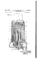
- Fig. 1 is a vertical sectional view ofthis improved centrifuge.
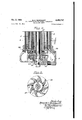
- Fig. 2 is a vertical sectional view of the lower half of the centrifuge showing one means for" pumping theoil back to the motor under pressure.
- Fig. 3 is a horizontal sectional view taken on line 3-3 of Fig. 2.
- Fig. 4 is a. vertical sectional view of the-lower half. of the centrifuge illustrating a somewhat different arrangement for the pumping of the oil back to the motor, and
- Fig. 5 is a bottom view of the centrifuge
- This improved centrifuge comprises a suitable supporting base or base housing 2, a casing 3' and its cover 4'.
- the bowl has its.
- top and bottom provided with tapered spindles I and 8, each having a set of these ball bearings,
- the drive to the bowl fromthe motor shaft I l is obtained by a tapered slip bushing ll' fitting,
- the spring operates not only to keep these parts in. contact but also acts as a safety for, with the bowl andv motor'runfning. at extremely highspeedbetween 7,000 and 10,000 R'. P. ML, this depending upon the amount of separation desired, it follows that in case of accident to the motor or bowl, the spring would prevent its transmission from one to the other.
- the inlet to the bowl is at the bottom instead of at the top as is the usual practice.
- a series of cylindrically formed ported chambers l5, l6 and I! Surrounding this tube is a series of cylindrically formed ported chambers l5, l6 and I! through which the oil passes from one to the other until it is finally discharged also at the bottom of the bowl back into the motor.
- the inlet tube I4 is located within a larger tube 7 l4 forming the inner wall of the chamber i! and has at the top thereof and just above the upper or outlet end of the tube 14, an impeller or propeller l8 of screw or worm form, the rotation of which with the bowl assists in forcing the liquid from the tube l4 through the laterally extending ports a formed in a top cover disk 19 of the bowl into the top of the outer annular chamber I5 from which it passes at the bottom of this chamber I5 through the ports 1) into the bottom of an intermediate annular chamber 16 from which it passes at the top thereof through ports e into an inner annular chamber I1 from which it passes through ports f at the bottom thereof through the outlet ports 9 of the base housing of the centrifuge back to the motor.
- the bowl spindle 8 is extended as by means of a shaft or supplemental spindle 8 suitably connected to or integral with the spindle 8 and which, likewise, is carried by ball bearings 20 and 2
- the inlet tube 14 is likewise extended to pass therethrough and this shaft is provided with vanes or spiral leaves 22 which act as a pump so that during the rotation of the bowl and its shaft, when the oil flows from the various chambers through the outlet of the bowl bottom into the housing 2 and before its passage therefrom, it is picked up by the vanes and forced through the outlet g of the housing at substantially the same pressure as when it was originally passed into the bowl and, therefore, a perfect cycle of the oil and clarification thereof is obtained with no loss of pressure since the'oil is forced back into the motor under substantially the same pressure as when it left the motor.
- the vanes of this pump are formed like the threads of a screw and the pitch may vary to determine the amount of pressure.
- Figs. 2 and 3 which is adapted especially for aeroplane motors where sufficient space is not available to take care of the extended shaft 8' of Fig. 4, the unit is provided with vanes 23 directly underneath the bottom of the bowl and rotate therewith.
- vanes may be formed as a part of the bottom disk of the bowl and pick the oil up immediately on its passage from the outlet f of the bowl and thus build up the pressure before it passes from the bowl and its housing back to the motor.
- the oil of the motor may be readily cleansed of its various foreign particles as it circulates from the motor to and through the centrifuge and not only this, but is fed back to the motor under substantially the same pressure at which it is maintained during its passage in the motor.
- a centrifuge comprising a housing-supported casing, a bowl supported in said casing for rotation and having ball-supported tapered spindles, a motor supported by the casing at the top of the bowl for rotating said bowl, said bowl comprising a plurality of cylinder-formed chambers therein,
- chambers-J having communicatmg: ports so located as to pass: the fiuidlfrom; the center of" the bowl: to the: outer chamber and from thencetoward the centerof rotation through. adjacent chambers and throughout: the length. of all. the chambers,. the. bowl having centrally thereof. an inlet at itsbottom. andalso. an. outlet at. its bottom communicating. with. the innermost. chamber.
- A. centrifuge comprising a housing-supported. casing, a bowl supported in: said. casing for rota.- tion, a. motorsupported. above said. bowl forr'o'tating it, said. bowl comprising a. plurality oi cylinder -formed. chambers therein; said chambers hav' ing communicating portsv so: located: as to pass. the. liquid. from the; center: of. the bowl to. the outer chamber. and. from thence toward; the. center' of. rotationthroughadjacent chambers andthrough out the length of all the chambers, the. bowlhaving centrally thereof. an inlet at its bottom and also an outlet at its. bottom communicating. with the innermost chamber,- said. inlet extending to near. the; top of the bowl, and an impeller located: at the top of said inlet.
- A. centrifuge comprising. a: housing-.-supp'orted casing, a. bowl supported in said casing forrotation and having ball-supported. tapered spindles, a motor supportedby the casing; at the top of the bowl for rotating said. bowl, said bowl: comprising a plurality of cylinder-formed. chambers therein, said chambers having communicating ports so located as to passthe fluid from. the center-f the bowl to the outer chamber. and. from. thence; toward the center of. rotation. through: adjacent chambers and. throughout. the length of all the chambers, the bowl having; centrally thereof an inlet. at its bottom and also an outlet atits bottom communicating with. the. innermost. chamber,, said inlet extending to-near' the top of. the: bowl, and an impeller located at the top of said. inlet;
- a centrifuge comprising.ahousing-supported casing, a bowlsupported in said casingv for rotation, a motor supported above said. bowl. for rotating; it, said bowl comprising a. plurality of cylin der-formed chambers therein, said chambers hav ing; communicating port's. so. located. as to pass the fluid fromthecenter ofz'thebowl to the-outer chamber and. from. thence. toward. the center" of rotation through adjacent: chambers. and throughout the length. oi all the chambers; the bowl havingv centrally" thereof. an inlet at. its: bottom and. also an outlet at its bottom communieating with the innermost. chamber; said inletv comprising.
- a centrifuge comprising. a. housin'g-F'supported casing, a rotatable bowl, spindle supperteidiatthe topand bottom. in: such. casing, a motor having a tapered cushionedslipjoint connection withthe bowl: and supported by a. casing'at the. top. of the bowl for rotatingv said bowl, said; bowl having a plurality of cylind-er formed nested: chambers therein, saidi chambers having communicating ports alternately located. at the top. and. bottom ofthe: chambers'soas to pass the fluid: lengthwise through the chambers'f'romthe center-of rotation to the outer: chamber" and. from.
- Acentrifuge comprising a housing-supported: casing, a rotatable bowl, spindle: supported. at its top and bottom. in such casing, a motor having a tapered cushioned slip joint connection. with the bowl. and. supported by the. casing at. the top of. the bowl for rotating said: bowl, said bowl having; a. plurality of. cylinder -formed nested chambers therein, said. chambers having com-- municating. ports alternately located at the: top? and bottom. of. the chambers so as. to. pass. the fluid lengthwise through the chambers. from the center of rotation to the outer chamber. andf-rom thence back toward the center of rotation through an adjacent chamber, theinlet to and outlet from the bowlbeing at the'b'ottom'thereof,
- the lower spindle of. the bowl having an supple-.
- said housing having an outlet, ancli means. carried by said supplemental spindle for: increasing the. pressure.- 01'; the fluid. as it leaves the-bowl and passes through the housing outlet of the centrifuge.
- Acentrifuge comprising ahousing-supported casing, a. bowlsupported in saidcasing for rota:- tion, a motor supported. above said bowl. for. rotating it, said bowl: comprising. a plurality oi cylinder-formed ported chambers. therein and having an outlet 'atits bottom. and an inlet centrally thereof also at its bottom and communicating with the top of the bowl, an impeller at the top of the bowl communicating'with said'inlot and with a chamber of the bowl, and means located below thebottom of the bowl and re tatable therewith for increasing the pressure of r the fluid passing fromthe-bowl.
- a centrifuge comprising a housing-supported casing, a, bowl supported in said casing for rotation and having a pair of taper-formed ball-bearing supported spindles, a motor supported above said bowl for rotating it and a tapered spring-cushioned connection between the motor and the upper tapered spindle of the bowl, said bowl comprising a plurality of cylinderformed ported members therein and having an outlet at its bottom and an inlet centrally thereof also at its bottom and communicating with the top of the bowl, and an impeller at the top of the bowl communicating with said inlet and with a chamber of the bowl.
- a centrifuge comprising a housing-supported casing, a bowl supported in said casing for rotation and having ball-supported tapered spindles, a motor supported by the casing at the top of the bowl for rotating said bowl, the upper tapered bowl spindle having a tapered seat and a tapered and spring-cushioned bushing connecting the shaft of the motor and bowl, said bowl comprising a plurality of cylinder-formed chambers therein, said chambers having communicating ports so located as to pass the fluid from the center of the bowl to the outer chamber and from thence toward the center of rotation through adjacent chambers and throughout the lengths of all the chambers, the bowl having centrally thereof an inlet at its bottom and also an outlet at its bottom communicating with the innermost chamber, the top of the bowl having laterally extending ports communicating With the inlet and with the outer chamber, a screw-formed impeller at the top of the inlet adjacent to the top of the bowl and in communication with the laterally extending ports leading to the outer chamber, and vane-formed means located below the bottom of the bowl
- a centrifuge comprising a housing-supported casing, a bowl supported in said casing for rotation, a motor supported above said bowl for rotating it, said bowl comprising a plurality of cylinder-formed ported chambers therein and having an outlet at its bottom and an inlet centrally thereof also at its bottom and communicating with the top of the bowl, and an impeller at the top of the bowl communicating with said inlet and with a chamber of the bowl and outlet means below the impeller and around said central inlet for de-airing the fluid.
- a centrifuge comprising a housing-supported casing, a bowl supported in said casing for rotation, a motor supported above said bowl for rotating it, said bowl comprising a plurality of cylinder-formed ported chambers therein and 7 vented chamber below said overflow chamber for the reception of said overflow fluid.
- a centrifuge comprising a housing-supported casing, a bowl supported in said'casing for rotation, a motor supported above said bowl for rotating it, said bowl comprising a plurality of cylinder-formed chambers therein, said chambers having communicating ports so located as to pass the liquid from the center of the bowl to the outer chamber and from thence toward the center of rotation through adjacent chambers and throughout the length of all the chambers, the bowl having centrally thereof an inlet at its bottom and also an outlet at its bottom communicating with the innermost chamber, said inlet extending to near the top of the bowl, and an impeller located at the top of said inlet and outlet means below the impeller and around said central inlet for de-airing the fluid.
- a centrifuge comprising a housing-supported casing, a bowl supported in said casing for rotation, a motor supported above said bowl for 'rotating it, said bowl comprising a plurality of the top of the bowl communicating with said inlet and with a chamber of the bowl, means located below the bottom of the bowl and rotatable therewith for increasing the pressure of the fluid passing from the bowl, and outlet means below the impeller and around said central inlet for de-airing the fluid.
- a centrifuge comprising a supporting base, a casing secured thereto, a cover for the casing, a rotary bowl in said casingand having tapered spindles at its top and bottom, ball bearings at the bottom of the bowl between one of said tapered spindles and base, ball bearings between the cover and the other of said tapered spindles, a motor on the cover and having spring-cushioned driving means to the top tapered spindle of the bowl, said bowl having an inlet and an outlet, .both at the bottom of the bowl, the inlet located centrally of the bowl and in communica: tion with ported chambers within the bowl for separating the fluid.
- a centrifuge comprising a supporting base, a casing secured thereto, a cover for the casing, a rotary bowl in said casing and having tapered spindles at its top and bottom, ball bearings at the bottom of the bowl between one of said tapered spindles and base, ball bearings between the cover and the other of said tapered spindles, a motor on the cover and having wring-cushioned driving means to the top tapered spindle of the bowl, said bowl having an inlet and an outlet, both at the bottom of the bowl, the inlet located centrally of the bowl and in communication with ported chambers within the bowl for separating the fluid, and an impeller located at the top of the bowl and in communication with the inlet located centrally of the bowl.
- a centrifuge comprising a supporting base, a casing secured thereto, a cover for the casing, a rotary bowl in said casing and having tapered spindles at its top and bottom, ball bearings at the bottom of the bowl .between one of said tapered spindles and base, ball bearings between the cover and the other of said tapered spindles, a motor on the cover and having driving means to the top tapered spindle of the bowl, said motor having a diameter substantially no greater than the diameter of the supporting casing, said bowl having an inlet and outlet both at the bottom of the bowl, the inlet located centrally REFERENCES CITED
- the following references are of record in the file of this patent:
Landscapes
- Centrifugal Separators (AREA)
Description
Oct. 5, 1948. B. C. RUNDQUIST OIL CENTRIFUGE WITH PLURAL CONCENTRIC SEPARATING ZONES 3 Sheets-Sheet 2 Filed Feb. 12, 1943 Patented Oct. 5, 1948 UNITED STATES PATENT OFFICE OIL CENTRIFUGE WITH PLURAL CONCEN TRIC SEPARATING ZONES Bennett C. Rundquist, Cleveland, Ohio, assignor' to The National Acme Company, Cleveland; Ohio, a corporation of Ohio Application February 12, 1943, Serial No. 475,639
20 Claims. (Cl. 233-31) As is well known, lubricating oil picks up dust and metal particles, and forms carbon and sludge during its circulation in the motor so that its repeated use is veryinjurious to expensive bear.- ingssuch as those used in high speed motors of aeroplanes, tanks, etc., and for the purpose of cleaning this oil it has heretofore been the practice to use filters but these filters quickly become clogged and have to be, cleaned frequently.
Therefore, for the. purpose of cleaning the oil'.
and separating therefrom all foreign matter, this improved centrifuge is provided, it being so constructed that it can be readily connected or attached to the motor so that the oil, after it once passes through the motor, then. passes through the centrifuge before it passes back into the motor. Consequently, any deleterious particles are removed and the efficiency of the motor increased and the life thereof prolonged.
The use of. centrifuges as usually constructed would not be possible in view of the limited space available in an aeroplane or tank and, therefore, it is the object. of this invention to provide a centrifuge that can be used in a practical way with aeroplanes and other motors in the limited space available for that purpose.
Furthermore, as the oil in the motor is usually pumped into the pipelines under a pressure of 25 to. 4.0 pounds, it follows that when this oil leaves the lines after its passage through the motor and enters the centrifuge for cleaning, this oil pressure. isnaturally reduced since it passes through, the. centrifuge at a gravity feed and it is essential, therefore, that when the oil passes back to the motor from the centrifuge, it pass thereinto under pressure.
Therefore, one of the objects of the present improvement is the provision of a centrifuge in which oil that passes from the motor to the centrifuge and from the centrifuge back to the motor will be transmitted to that motor under substant ally the same pressure'under which it was used while'in the, motor.
The present improvement therefore'has' to do with'rtheprovision of a simple, compact and effident-centrifuge particularly adapted. for clean- 2 ingthe oil used in the motor during its circulation cycle.
In the drawings accompanying and forming a part'of this specification, I I
Fig. 1 is a vertical sectional view ofthis improved centrifuge. i Fig. 2 is a vertical sectional view of the lower half of the centrifuge showing one means for" pumping theoil back to the motor under pressure. Fig. 3 is a horizontal sectional view taken on line 3-3 of Fig. 2.
Fig. 4 is a. vertical sectional view of the-lower half. of the centrifuge illustrating a somewhat different arrangement for the pumping of the oil back to the motor, and
' Fig. 5 is a bottom view of the centrifuge;
Similar reference characters indicate correspondingparts' in the several views. I
Before explaining in detail the present improvement and its mode of operation, I desire it understood that the invention is not limited to the details of construction and arrangement of parts illustrated in the accompanying drawings since the invention is capable of other embodiments, and that the. phraseology employed is" for the purpose of description and not. offlimita- I tion;
This improved centrifuge comprises a suitable supporting base or base housing 2, a casing 3' and its cover 4'.
In the casing 3 is'located a rotatable bowl 5 d bearings and for this purpose the bowl has its.
top and bottom provided with tapered spindles I and 8, each having a set of these ball bearings,
one set 9. at. thetopf andthe other set ID. at the.
bottom., p
The drive to the bowl fromthe motor shaft I l is obtained by a tapered slip bushing ll' fitting,
a tapered seat l2 in thetapered spindlefl'l, a. spring It being provided between the tapered bushing and the motor drive H to care for the: friction between the parts.
As thisdrive from the motor to the bowl is through a tapered fitting or joint between the I motor shaft and the bowl, the spring operates not only to keep these parts in. contact but also acts as a safety for, with the bowl andv motor'runfning. at extremely highspeedbetween 7,000 and 10,000 R'. P. ML, this depending upon the amount of separation desired, it follows that in case of accident to the motor or bowl, the spring would prevent its transmission from one to the other. Extending upwardly into the bowl to near the top and at the center thereof is an inlet tube l4 forfeeding the oil from the motor into the bowl. Thus, the inlet to the bowl is at the bottom instead of at the top as is the usual practice.
Surrounding this tube is a series of cylindrically formed ported chambers l5, l6 and I! through which the oil passes from one to the other until it is finally discharged also at the bottom of the bowl back into the motor.
The inlet tube I4 is located within a larger tube 7 l4 forming the inner wall of the chamber i! and has at the top thereof and just above the upper or outlet end of the tube 14, an impeller or propeller l8 of screw or worm form, the rotation of which with the bowl assists in forcing the liquid from the tube l4 through the laterally extending ports a formed in a top cover disk 19 of the bowl into the top of the outer annular chamber I5 from which it passes at the bottom of this chamber I5 through the ports 1) into the bottom of an intermediate annular chamber 16 from which it passes at the top thereof through ports e into an inner annular chamber I1 from which it passes through ports f at the bottom thereof through the outlet ports 9 of the base housing of the centrifuge back to the motor.
It will thus be observed that as the oil passes from the motor into the tube M at the bottom of the centrifuge, it is circulated through-the entire lengths of the various chambers, as indicated by the arrows on the drawings, and during this circulation and rotation, it is cleaned of all foreign particles which are thus removed therefrom before the passage of the oil back to the motor.
Thus, the dirty oil entering the centrifuge from the motor is cleaned and clarified and so passes back into the motor practically in the same condition as when it was first poured thereinto and, consequently, the bearings and other moving parts of the motor are not injured by the foreign matter which is picked up by the oil during its circulation through the motor as would be the case where this oil continued to circulate through the motor or even with filters which imperfectly clean it.
At the top of the tube l4 there is clearance between this tube l4 and the screw [8. This is to provide an overflow in case flow of oil becomes blocked in its passage at some place in the bowl. If this happens, the oil will then pass down the chamber or tube [4' formed between the tube l4 and this tube M past a clearance ring [4" at the bottom of the tube I4 into a chamber 24 and out the vent 25.
Also, as the all returns to the centrifuge from the motor, it has from fifty to seventy per cent air. This air must be removed. As the oil only is forced through the screw IS, the air entering the centrifuge with the oil is forced down the overflow chamber or tube 14' past the ring l4" intothe chamber 24 and out the vent 25, thus eliminating de-airing tanks now used with motors.
It will be observed that the several chambers and the bowl parts are readily assembled and separablejorcleaning purposes and for the removal of the sludge that may accumulate in the bottom of any chamber.
The oil circulating in motors of the class described is usually pumped into the pipe lines under a considerable pressure, for instance, from twenty-five to forty pounds. Consequently, since the oil pressure is naturally reduced when the oil passes from the motor into the centrifuge for cleaning as it passes through the centrifuge at gravity feed, when the oil passes back from the centrifuge to the motor, it is essential that it pass into the motor under pressure and, for this purpose, this improved centrifuge is provided with means for passing the oil from the centrifuge into the motor under the desired pressure and since the available space, as before stated, is very limited, especially in aeroplanes and tanks, this pressure means, in the form of a pump, is a part of the centrifuge and is located at the bottom of the bowl and in the housing supporting that bowl, the housing being constructed for that purpose.
In one form thereof (see Fig. 4) the bowl spindle 8 is extended as by means of a shaft or supplemental spindle 8 suitably connected to or integral with the spindle 8 and which, likewise, is carried by ball bearings 20 and 2|.
The inlet tube 14 is likewise extended to pass therethrough and this shaft is provided with vanes or spiral leaves 22 which act as a pump so that during the rotation of the bowl and its shaft, when the oil flows from the various chambers through the outlet of the bowl bottom into the housing 2 and before its passage therefrom, it is picked up by the vanes and forced through the outlet g of the housing at substantially the same pressure as when it was originally passed into the bowl and, therefore, a perfect cycle of the oil and clarification thereof is obtained with no loss of pressure since the'oil is forced back into the motor under substantially the same pressure as when it left the motor.
The vanes of this pump are formed like the threads of a screw and the pitch may vary to determine the amount of pressure.
In the form shown in Figs. 2 and 3 which is adapted especially for aeroplane motors where sufficient space is not available to take care of the extended shaft 8' of Fig. 4, the unit is provided with vanes 23 directly underneath the bottom of the bowl and rotate therewith.
These vanes may be formed as a part of the bottom disk of the bowl and pick the oil up immediately on its passage from the outlet f of the bowl and thus build up the pressure before it passes from the bowl and its housing back to the motor.
Thus, by this very simple, compact and efficient centrifuge, the oil of the motor may be readily cleansed of its various foreign particles as it circulates from the motor to and through the centrifuge and not only this, but is fed back to the motor under substantially the same pressure at which it is maintained during its passage in the motor.
It is to be understood that, by describing in detail herein any particular forms, structure or arrangement, it is not intended to limit the invention beyond the terms of the several claims or the requirements of the prior art. 7
Having thus explained the nature of my said invention and described a way of constructing and using the same, although without attempting to set forth all of the forms in which it may be made or all of the modes of its use, I claim:
1. A centrifuge comprising a housing-supported casing, a bowl supported in said casing for rotation and having ball-supported tapered spindles, a motor supported by the casing at the top of the bowl for rotating said bowl, said bowl comprising a plurality of cylinder-formed chambers therein,
arrears? said; chambers-J having communicatmg: ports so located as to pass: the fiuidlfrom; the center of" the bowl: to the: outer chamber and from thencetoward the centerof rotation through. adjacent chambers and throughout: the length. of all. the chambers,. the. bowl having centrally thereof. an inlet at itsbottom. andalso. an. outlet at. its bottom communicating. with. the innermost. chamber.
2; A. centrifuge comprising a housing-supported. casing, a bowl supported in: said. casing for rota.- tion, a. motorsupported. above said. bowl forr'o'tating it, said. bowl comprising a. plurality oi cylinder -formed. chambers therein; said chambers hav' ing communicating portsv so: located: as to pass. the. liquid. from the; center: of. the bowl to. the outer chamber. and. from thence toward; the. center' of. rotationthroughadjacent chambers andthrough out the length of all the chambers, the. bowlhaving centrally thereof. an inlet at its bottom and also an outlet at its. bottom communicating. with the innermost chamber,- said. inlet extending to near. the; top of the bowl, and an impeller located: at the top of said inlet.
3, A. centrifuge comprising. a: housing-.-supp'orted casing, a. bowl supported in said casing forrotation and having ball-supported. tapered spindles, a motor supportedby the casing; at the top of the bowl for rotating said. bowl, said bowl: comprising a plurality of cylinder-formed. chambers therein, said chambers having communicating ports so located as to passthe fluid from. the center-f the bowl to the outer chamber. and. from. thence; toward the center of. rotation. through: adjacent chambers and. throughout. the length of all the chambers, the bowl having; centrally thereof an inlet. at its bottom and also an outlet atits bottom communicating with. the. innermost. chamber,, said inlet extending to-near' the top of. the: bowl, and an impeller located at the top of said. inlet;
4. A centrifuge comprising.ahousing-supported casing, a bowlsupported in said casingv for rotation, a motor supported above said. bowl. for rotating; it, said bowl comprising a. plurality of cylin der-formed chambers therein, said chambers hav ing; communicating port's. so. located. as to pass the fluid fromthecenter ofz'thebowl to the-outer chamber and. from. thence. toward. the center" of rotation through adjacent: chambers. and throughout the length. oi all the chambers; the bowl havingv centrally" thereof. an inlet at. its: bottom and. also an outlet at its bottom communieating with the innermost. chamber; said inletv comprising. a tube located within a larger tube: forming the inner wall of therinner. chamber. of the bowl and having its outlet below the top of the bowland incommunicati'onwith.laterally ex tending. ports in atop cover'disk of. the bowl, and an impeller located between. said: tube outlet: and saidlast'portsz.
5:. A centrifugecomprising a housing' supported casing, a rotatable bowl, spindle supported at-the top and bottomin suchcasing, a motor having a tapered cushioned slip joint connection with the bowl and supported by the casi'ngat the topof the bowl for rotating said bowl, said bowl having a plurality of cylinder-formed. nested. chambers therein, said" chambers. having communicating ports alternately located at the top and bottom of the chambers so as tov pass the fluid lengthwise through the chambers from the center of rotation to the outer chamber and from thence-back toward the center of rotation through an adjacent chambenthe inlet to and outlet from the bowl be.-- ing at the bottom thereof, andan. impeller.
cated at the toprof the bowl; and incommunica tion with. the inlet and outer chamber.
6.. A centrifuge. comprising. a. housin'g-F'supported casing, a rotatable bowl, spindle supperteidiatthe topand bottom. in: such. casing, a motor having a tapered cushionedslipjoint connection withthe bowl: and supported by a. casing'at the. top. of the bowl for rotatingv said bowl, said; bowl having a plurality of cylind-er formed nested: chambers therein, saidi chambers having communicating ports alternately located. at the top. and. bottom ofthe: chambers'soas to pass the fluid: lengthwise through the chambers'f'romthe center-of rotation to the outer: chamber" and. from. thence back: to?- ward the center of rotation through an adjacent chamber, the: inlet to: and. outlet from the bowl being at the bottom thereof, an impeller: located at the top of the bowl and in. communicationwith the inlet and outer chambenand. rotatable means for. increasing. the pressure of the fluid. assing. from the bowl and located below the bottom of the bowl and in communication with the outlet therefrom and. rotable' with the bowl.
7. Acentrifuge comprising a housing-supported: casing, a rotatable bowl, spindle: supported. at its top and bottom. in such casing, a motor having a tapered cushioned slip joint connection. with the bowl. and. supported by the. casing at. the top of. the bowl for rotating said: bowl, said bowl having; a. plurality of. cylinder -formed nested chambers therein, said. chambers having com-- municating. ports alternately located at the: top? and bottom. of. the chambers so as. to. pass. the fluid lengthwise through the chambers. from the center of rotation to the outer chamber. andf-rom thence back toward the center of rotation through an adjacent chamber, theinlet to and outlet from the bowlbeing at the'b'ottom'thereof,
the lower: spindle of. the bowl having an supple-.
mental ball-supportedspindle, said housing having an outlet, ancli means. carried by said supplemental spindle for: increasing the. pressure.- 01'; the fluid. as it leaves the-bowl and passes through the housing outlet of the centrifuge.
8. A centrifuge-comprising.ahousing-supported;
casing, a bowl supported in said. casing forv ro tation, a motor supported. above. said: bowl for rotating it,, said bowl. comprising a plurality of. cylinder-formed. ported. chambers therein. and. having. an outlet-at its. bottom. and an inlet. contrally thereof also at its. bottom and. communieating with the: top of the-bowl, and: an impeller at the top of the bowl communicating with said inlet and. with a chamber of the bowl.
9. Acentrifuge comprising ahousing-supported casing, a. bowlsupported in saidcasing for rota:- tion, a motor supported. above said bowl. for. rotating it, said bowl: comprising. a plurality oi cylinder-formed ported chambers. therein and having an outlet 'atits bottom. and an inlet centrally thereof also at its bottom and communicating with the top of the bowl, an impeller at the top of the bowl communicating'with said'inlot and with a chamber of the bowl, and means located below thebottom of the bowl and re tatable therewith for increasing the pressure of r the fluid passing fromthe-bowl.
bearing supported spindles; a motor supported.
above said bowl'for. rotating it, said.bowl.compris-- ing a plurality of cylinder forme'd ported chamaberstherein. and having. an. outlet at; its bottom: and. an inlet. centrally thereofalso at its. bottom and communicating with the top of the bowl, and an impeller at the top of the bowl communicating with said inlet and with a chamber of the bowl.
11. A centrifuge comprising a housing-supported casing, a, bowl supported in said casing for rotation and having a pair of taper-formed ball-bearing supported spindles, a motor supported above said bowl for rotating it and a tapered spring-cushioned connection between the motor and the upper tapered spindle of the bowl, said bowl comprising a plurality of cylinderformed ported members therein and having an outlet at its bottom and an inlet centrally thereof also at its bottom and communicating with the top of the bowl, and an impeller at the top of the bowl communicating with said inlet and with a chamber of the bowl.
12. A centrifuge comprising a housing-supported casing, a bowl supported in said casing for rotation and having ball-supported tapered spindles, a motor supported by the casing at the top of the bowl for rotating said bowl, the upper tapered bowl spindle having a tapered seat and a tapered and spring-cushioned bushing connecting the shaft of the motor and bowl, said bowl comprising a plurality of cylinder-formed chambers therein, said chambers having communicating ports so located as to pass the fluid from the center of the bowl to the outer chamber and from thence toward the center of rotation through adjacent chambers and throughout the lengths of all the chambers, the bowl having centrally thereof an inlet at its bottom and also an outlet at its bottom communicating with the innermost chamber, the top of the bowl having laterally extending ports communicating With the inlet and with the outer chamber, a screw-formed impeller at the top of the inlet adjacent to the top of the bowl and in communication with the laterally extending ports leading to the outer chamber, and vane-formed means located below the bottom of the bowl and rotatable therewith and communicating with a housing outlet below the bottom of the bowl for increasing the pressure of the fluid passing from the bowl.
13. A centrifuge comprising a housing-supported casing, a bowl supported in said casing for rotation, a motor supported above said bowl for rotating it, said bowl comprising a plurality of cylinder-formed ported chambers therein and having an outlet at its bottom and an inlet centrally thereof also at its bottom and communicating with the top of the bowl, and an impeller at the top of the bowl communicating with said inlet and with a chamber of the bowl and outlet means below the impeller and around said central inlet for de-airing the fluid.
14. A centrifuge comprising a housing-supported casing, a bowl supported in said casing for rotation, a motor supported above said bowl for rotating it, said bowl comprising a plurality of cylinder-formed ported chambers therein and 7 vented chamber below said overflow chamber for the reception of said overflow fluid.
15. A centrifuge comprising a housing-supported casing, a bowl supported in said'casing for rotation, a motor supported above said bowl for rotating it, said bowl comprising a plurality of cylinder-formed chambers therein, said chambers having communicating ports so located as to pass the liquid from the center of the bowl to the outer chamber and from thence toward the center of rotation through adjacent chambers and throughout the length of all the chambers, the bowl having centrally thereof an inlet at its bottom and also an outlet at its bottom communicating with the innermost chamber, said inlet extending to near the top of the bowl, and an impeller located at the top of said inlet and outlet means below the impeller and around said central inlet for de-airing the fluid.
16. A centrifuge comprising a housing-supported casing, a bowl supported in said casing for rotation, a motor supported above said bowl for rotating-it, said bowl comprising a, plurality of cylinder-formed chambers therein, said chambers having communicating ports so located as to pass the fluid from the center of the bowl to the outer chamber and from thence toward the center of rotation through adjacent chambers and throughout the length of all the chambers, the bowl having centrally thereof an inlet at its bottom and extending to communicate with the top of the bowland also an outlet at its bottom communicating with the innermost chamber, said housing having an outlet below the bottom of the bowl, means located below the bottom of the bowl and in communication with the housing outlet for increasing the pressure of the fluid passing from the bowl, an impeller located at the top of said inlet, and means below the impeller and adjacent to said central inlet for de-airing the fluid and comprising an overflow chamber around the centrally located inlet and having a clearance or port at its bottom for the passage of overflow fluid and the removal of air from the 5 l=fluid and a vented chamber below said overflow chamber for the reception of said overflow fluid.
17. A centrifuge comprising a housing-supported casing, a bowl supported in said casing for rotation, a motor supported above said bowl for 'rotating it, said bowl comprising a plurality of the top of the bowl communicating with said inlet and with a chamber of the bowl, means located below the bottom of the bowl and rotatable therewith for increasing the pressure of the fluid passing from the bowl, and outlet means below the impeller and around said central inlet for de-airing the fluid.
18. A centrifuge comprising a supporting base, a casing secured thereto, a cover for the casing, a rotary bowl in said casingand having tapered spindles at its top and bottom, ball bearings at the bottom of the bowl between one of said tapered spindles and base, ball bearings between the cover and the other of said tapered spindles, a motor on the cover and having spring-cushioned driving means to the top tapered spindle of the bowl, said bowl having an inlet and an outlet, .both at the bottom of the bowl, the inlet located centrally of the bowl and in communica: tion with ported chambers within the bowl for separating the fluid.
.9 19. A centrifuge comprising a supporting base, a casing secured thereto, a cover for the casing, a rotary bowl in said casing and having tapered spindles at its top and bottom, ball bearings at the bottom of the bowl between one of said tapered spindles and base, ball bearings between the cover and the other of said tapered spindles, a motor on the cover and having wring-cushioned driving means to the top tapered spindle of the bowl, said bowl having an inlet and an outlet, both at the bottom of the bowl, the inlet located centrally of the bowl and in communication with ported chambers within the bowl for separating the fluid, and an impeller located at the top of the bowl and in communication with the inlet located centrally of the bowl.
2 0. A centrifuge comprising a supporting base, a casing secured thereto, a cover for the casing, a rotary bowl in said casing and having tapered spindles at its top and bottom, ball bearings at the bottom of the bowl .between one of said tapered spindles and base, ball bearings between the cover and the other of said tapered spindles, a motor on the cover and having driving means to the top tapered spindle of the bowl, said motor having a diameter substantially no greater than the diameter of the supporting casing, said bowl having an inlet and outlet both at the bottom of the bowl, the inlet located centrally REFERENCES CITED The following references are of record in the file of this patent:
UNITED STATES PATENTS Number Name Date 1,403,341 Mortensen Jan. 10, 1922 1,537,471 Karpinsky et a1. May 12, 1925 1,714,985 Paterson May 28, 1929 1,783,546 Petsche et a1. Dec. 2, 1930 1,956,496 Degerth Apr. 24, 1934 2,085,929 Strafford et a1. July 6, 1937 2,107,035 l-Iall Feb. 1, 1938 2,138,468, Ayres Nov. 29, 1938 2,321,144 Jones June 8, 1943 FOREIGN PATENTS Number Country Date 251,633 Germany Oct. 5, 1912 451,026 Germany Oct. 19, 1927 470,723 Germany Jan. 25, 1929 610,305 Germany Mar. 9, 1935 728,018
France June 28, 1938
Priority Applications (1)
| Application Number | Priority Date | Filing Date | Title |
|---|---|---|---|
| US475639A US2450737A (en) | 1943-02-12 | 1943-02-12 | Oil centrifuge with plural concentric separating zones |
Applications Claiming Priority (1)
| Application Number | Priority Date | Filing Date | Title |
|---|---|---|---|
| US475639A US2450737A (en) | 1943-02-12 | 1943-02-12 | Oil centrifuge with plural concentric separating zones |
Publications (1)
| Publication Number | Publication Date |
|---|---|
| US2450737A true US2450737A (en) | 1948-10-05 |
Family
ID=23888468
Family Applications (1)
| Application Number | Title | Priority Date | Filing Date |
|---|---|---|---|
| US475639A Expired - Lifetime US2450737A (en) | 1943-02-12 | 1943-02-12 | Oil centrifuge with plural concentric separating zones |
Country Status (1)
| Country | Link |
|---|---|
| US (1) | US2450737A (en) |
Cited By (16)
| Publication number | Priority date | Publication date | Assignee | Title |
|---|---|---|---|---|
| US2646921A (en) * | 1951-08-31 | 1953-07-28 | James S Adams | Device for separating oil from water |
| US2858064A (en) * | 1954-12-21 | 1958-10-28 | Raymond W Clow | Mineral separator |
| US3050240A (en) * | 1958-03-28 | 1962-08-21 | Dynamic Filters Inc | Centrifugal contaminant extractor |
| US3178105A (en) * | 1962-05-28 | 1965-04-13 | Michigan Dynamics Inc | Contaminant extracting boost pump |
| US3235174A (en) * | 1961-01-24 | 1966-02-15 | Aero Flow Dynamics Inc | Centrifugal liquid purifier |
| US4091988A (en) * | 1976-06-21 | 1978-05-30 | Albert G. Bodine | Centrifugal trap for solid particles |
| US4228951A (en) * | 1977-06-20 | 1980-10-21 | Berber Viktor A | Centrifugal liquid purifier |
| WO1988004950A1 (en) * | 1987-01-10 | 1988-07-14 | Walter Hamacher | Rotor for centrifugal separators used for degassing liquids |
| US5944648A (en) * | 1996-10-15 | 1999-08-31 | Cornay; Paul J. | Concentric tubular centrifuge |
| US20040112824A1 (en) * | 2002-12-16 | 2004-06-17 | Adelbert Gorham | High efficiency self-cleaning centrifuge |
| US20040142807A1 (en) * | 1997-10-14 | 2004-07-22 | Cornay Paul J. | Concentric tubular centrifuge |
| US6808481B1 (en) | 1996-10-15 | 2004-10-26 | Erth Technologies, Inc. | Concentric tubular centrifuge |
| US20050054507A1 (en) * | 1996-10-15 | 2005-03-10 | Cornay Paul J. | Concentric tubular centrifuge |
| US20060258522A1 (en) * | 2003-08-30 | 2006-11-16 | Cornay Paul J | Centrifuge |
| RU2304607C2 (en) * | 2004-06-18 | 2007-08-20 | Владимир Николаевич Смагилов | Petroleum processing process and apparatus |
| US20080026926A1 (en) * | 2006-07-31 | 2008-01-31 | Advanced Products Laboratories, Inc. | Methods and apparatus for centrifuging dry solids |
Citations (14)
| Publication number | Priority date | Publication date | Assignee | Title |
|---|---|---|---|---|
| DE251633C (en) * | 1911-02-25 | |||
| US1403341A (en) * | 1919-03-21 | 1922-01-10 | Mortensen Frantz | Arrangement for separators with hanging bowls |
| US1537471A (en) * | 1924-01-16 | 1925-05-12 | Karpinsky Stephan | Installation for the separation of liquids |
| DE451026C (en) * | 1927-10-19 | Bergedorfer Eisenwerk Akt Ges | Spin for cleaning oil for internal combustion engines, especially aircraft engines | |
| DE470723C (en) * | 1925-06-07 | 1929-01-25 | Hans Luecker | Standing liquid centrifugal drum with upper feed and discharge of the centrifuged material through axial pipes |
| US1714985A (en) * | 1927-07-25 | 1929-05-28 | Nat Acme Co | Centrifuge |
| US1783546A (en) * | 1929-09-07 | 1930-12-02 | Nat Acme Co | Centrifuge |
| FR728018A (en) * | 1930-12-09 | 1932-06-28 | Separator Soc Ab | Device relating to centrifuge bowls |
| US1956496A (en) * | 1932-03-23 | 1934-04-24 | Maskin Och Brobyggnads Ab | Bowl for clarifying fluids |
| DE610305C (en) * | 1930-09-18 | 1935-03-09 | Bergedorfer Eisenwerk Akt Ges | Centrifugal drum with airtight connected feed line for the centrifugal fluid |
| US2085929A (en) * | 1932-10-26 | 1937-07-06 | Nat Acme Co | Centrifuge |
| US2107035A (en) * | 1934-02-16 | 1938-02-01 | Laval Separator Co De | Closed centrifugal separator |
| US2138468A (en) * | 1936-03-17 | 1938-11-29 | Sharples Specialty Co | Centrifugal separator |
| US2321144A (en) * | 1940-02-19 | 1943-06-08 | Sharples Corp | Centrifugal purification of liquids |
-
1943
- 1943-02-12 US US475639A patent/US2450737A/en not_active Expired - Lifetime
Patent Citations (14)
| Publication number | Priority date | Publication date | Assignee | Title |
|---|---|---|---|---|
| DE451026C (en) * | 1927-10-19 | Bergedorfer Eisenwerk Akt Ges | Spin for cleaning oil for internal combustion engines, especially aircraft engines | |
| DE251633C (en) * | 1911-02-25 | |||
| US1403341A (en) * | 1919-03-21 | 1922-01-10 | Mortensen Frantz | Arrangement for separators with hanging bowls |
| US1537471A (en) * | 1924-01-16 | 1925-05-12 | Karpinsky Stephan | Installation for the separation of liquids |
| DE470723C (en) * | 1925-06-07 | 1929-01-25 | Hans Luecker | Standing liquid centrifugal drum with upper feed and discharge of the centrifuged material through axial pipes |
| US1714985A (en) * | 1927-07-25 | 1929-05-28 | Nat Acme Co | Centrifuge |
| US1783546A (en) * | 1929-09-07 | 1930-12-02 | Nat Acme Co | Centrifuge |
| DE610305C (en) * | 1930-09-18 | 1935-03-09 | Bergedorfer Eisenwerk Akt Ges | Centrifugal drum with airtight connected feed line for the centrifugal fluid |
| FR728018A (en) * | 1930-12-09 | 1932-06-28 | Separator Soc Ab | Device relating to centrifuge bowls |
| US1956496A (en) * | 1932-03-23 | 1934-04-24 | Maskin Och Brobyggnads Ab | Bowl for clarifying fluids |
| US2085929A (en) * | 1932-10-26 | 1937-07-06 | Nat Acme Co | Centrifuge |
| US2107035A (en) * | 1934-02-16 | 1938-02-01 | Laval Separator Co De | Closed centrifugal separator |
| US2138468A (en) * | 1936-03-17 | 1938-11-29 | Sharples Specialty Co | Centrifugal separator |
| US2321144A (en) * | 1940-02-19 | 1943-06-08 | Sharples Corp | Centrifugal purification of liquids |
Cited By (22)
| Publication number | Priority date | Publication date | Assignee | Title |
|---|---|---|---|---|
| US2646921A (en) * | 1951-08-31 | 1953-07-28 | James S Adams | Device for separating oil from water |
| US2858064A (en) * | 1954-12-21 | 1958-10-28 | Raymond W Clow | Mineral separator |
| US3050240A (en) * | 1958-03-28 | 1962-08-21 | Dynamic Filters Inc | Centrifugal contaminant extractor |
| US3235174A (en) * | 1961-01-24 | 1966-02-15 | Aero Flow Dynamics Inc | Centrifugal liquid purifier |
| US3178105A (en) * | 1962-05-28 | 1965-04-13 | Michigan Dynamics Inc | Contaminant extracting boost pump |
| US4091988A (en) * | 1976-06-21 | 1978-05-30 | Albert G. Bodine | Centrifugal trap for solid particles |
| US4228951A (en) * | 1977-06-20 | 1980-10-21 | Berber Viktor A | Centrifugal liquid purifier |
| WO1988004950A1 (en) * | 1987-01-10 | 1988-07-14 | Walter Hamacher | Rotor for centrifugal separators used for degassing liquids |
| US5944648A (en) * | 1996-10-15 | 1999-08-31 | Cornay; Paul J. | Concentric tubular centrifuge |
| US6142924A (en) * | 1996-10-15 | 2000-11-07 | Erth Llc | Concentric tubular centrifuge |
| US6808481B1 (en) | 1996-10-15 | 2004-10-26 | Erth Technologies, Inc. | Concentric tubular centrifuge |
| US20050054507A1 (en) * | 1996-10-15 | 2005-03-10 | Cornay Paul J. | Concentric tubular centrifuge |
| US7189196B2 (en) | 1997-10-14 | 2007-03-13 | Erth Technologies, Inc. | Method of separating materials with a concentric tubular centrifuge |
| US20040142807A1 (en) * | 1997-10-14 | 2004-07-22 | Cornay Paul J. | Concentric tubular centrifuge |
| US6966874B2 (en) | 1997-10-14 | 2005-11-22 | Erth Technologies, Inc. | Concentric tubular centrifuge |
| US20040112824A1 (en) * | 2002-12-16 | 2004-06-17 | Adelbert Gorham | High efficiency self-cleaning centrifuge |
| US7077799B2 (en) * | 2002-12-16 | 2006-07-18 | Advanced Products Laboratories, Inc. | Apparatus and method for a high-efficiency self-cleaning centrifuge having concentrate cylinders |
| US20060258522A1 (en) * | 2003-08-30 | 2006-11-16 | Cornay Paul J | Centrifuge |
| US7241256B2 (en) | 2003-08-30 | 2007-07-10 | Erth Technologies, Inc. | Centrifuge |
| RU2304607C2 (en) * | 2004-06-18 | 2007-08-20 | Владимир Николаевич Смагилов | Petroleum processing process and apparatus |
| US20080026926A1 (en) * | 2006-07-31 | 2008-01-31 | Advanced Products Laboratories, Inc. | Methods and apparatus for centrifuging dry solids |
| US7901343B2 (en) | 2006-07-31 | 2011-03-08 | Advanced Products Laboratories, Inc. | Methods and apparatus for centrifuging dry solids |
Similar Documents
| Publication | Publication Date | Title |
|---|---|---|
| US2450737A (en) | Oil centrifuge with plural concentric separating zones | |
| US3624822A (en) | Gas separator for a submersible oil pump | |
| EP0035498B1 (en) | Centrifugal separator | |
| US2406308A (en) | Filter | |
| GB1089355A (en) | Centrifugal fluid cleaners | |
| US4353499A (en) | Centrifugal separator | |
| US4481111A (en) | Self-cleaning filter with motor incorporated therewith | |
| US3791576A (en) | Centrifuge | |
| US2650022A (en) | Centrifuge for cleaning liquids | |
| CN1013931B (en) | Cleaning of centrifugal separator | |
| US3957650A (en) | Acoustic centrifuge | |
| US2733855A (en) | Multistage | |
| US2269716A (en) | Pump and clarifier | |
| US1906417A (en) | Filtering apparatus | |
| US3275148A (en) | Anti clog device for lubricating system | |
| US1242560A (en) | Oil purifier and pump. | |
| US3075693A (en) | Centrifuge filtration | |
| US3795457A (en) | Multistage pitot pump with means for feeding clean fluid to seals | |
| US3235174A (en) | Centrifugal liquid purifier | |
| US2741333A (en) | Oil purification | |
| GB1035542A (en) | Improvements in or relating to centrifugal separators | |
| US1042295A (en) | Filtering apparatus. | |
| GB2049494A (en) | Centrifugal separator | |
| US2085075A (en) | Crankcase flusher and cleaner | |
| US2101211A (en) | Filter |