US2440887A - Antirattle device for windows and the like - Google Patents
Antirattle device for windows and the like Download PDFInfo
- Publication number
- US2440887A US2440887A US692454A US69245446A US2440887A US 2440887 A US2440887 A US 2440887A US 692454 A US692454 A US 692454A US 69245446 A US69245446 A US 69245446A US 2440887 A US2440887 A US 2440887A
- Authority
- US
- United States
- Prior art keywords
- sash
- receptacle
- frame
- windows
- socket
- Prior art date
- Legal status (The legal status is an assumption and is not a legal conclusion. Google has not performed a legal analysis and makes no representation as to the accuracy of the status listed.)
- Expired - Lifetime
Links
- 238000010276 construction Methods 0.000 description 2
- 239000002184 metal Substances 0.000 description 2
- 239000011521 glass Substances 0.000 description 1
- 230000004048 modification Effects 0.000 description 1
- 238000012986 modification Methods 0.000 description 1
- 239000002023 wood Substances 0.000 description 1
Images
Classifications
-
- E—FIXED CONSTRUCTIONS
- E06—DOORS, WINDOWS, SHUTTERS, OR ROLLER BLINDS IN GENERAL; LADDERS
- E06B—FIXED OR MOVABLE CLOSURES FOR OPENINGS IN BUILDINGS, VEHICLES, FENCES OR LIKE ENCLOSURES IN GENERAL, e.g. DOORS, WINDOWS, BLINDS, GATES
- E06B3/00—Window sashes, door leaves, or like elements for closing wall or like openings; Layout of fixed or moving closures, e.g. windows in wall or like openings; Features of rigidly-mounted outer frames relating to the mounting of wing frames
- E06B3/32—Arrangements of wings characterised by the manner of movement; Arrangements of movable wings in openings; Features of wings or frames relating solely to the manner of movement of the wing
- E06B3/34—Arrangements of wings characterised by the manner of movement; Arrangements of movable wings in openings; Features of wings or frames relating solely to the manner of movement of the wing with only one kind of movement
- E06B3/42—Sliding wings; Details of frames with respect to guiding
- E06B3/44—Vertically-sliding wings
- E06B2003/4438—Vertically-sliding wings characterised by the material used for the frames
- E06B2003/4446—Wood
-
- E—FIXED CONSTRUCTIONS
- E06—DOORS, WINDOWS, SHUTTERS, OR ROLLER BLINDS IN GENERAL; LADDERS
- E06B—FIXED OR MOVABLE CLOSURES FOR OPENINGS IN BUILDINGS, VEHICLES, FENCES OR LIKE ENCLOSURES IN GENERAL, e.g. DOORS, WINDOWS, BLINDS, GATES
- E06B3/00—Window sashes, door leaves, or like elements for closing wall or like openings; Layout of fixed or moving closures, e.g. windows in wall or like openings; Features of rigidly-mounted outer frames relating to the mounting of wing frames
- E06B3/32—Arrangements of wings characterised by the manner of movement; Arrangements of movable wings in openings; Features of wings or frames relating solely to the manner of movement of the wing
- E06B3/34—Arrangements of wings characterised by the manner of movement; Arrangements of movable wings in openings; Features of wings or frames relating solely to the manner of movement of the wing with only one kind of movement
- E06B3/42—Sliding wings; Details of frames with respect to guiding
- E06B3/44—Vertically-sliding wings
- E06B3/4407—Single-hung, i.e. having a single vertical sliding panel
Definitions
- This invention relates to improvements in antirattling device for window sash and the like.
- the principal object of the invention is the provision of an antirattling device which is adapted for association with a window frame and sash to prevent rattling of the sash in the frame.
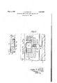
- Fig. 1 is a partial front elevational view of the side portion of a sash and an adjacent portion of a window frame with the device of the invention associated therewith;
- Fig. 2 is a plan view of the device shown in Fig. 1.
- FIG. 1 A portion of a side of a window is shown in Fig, 1 wherein the side member of the sash is represented by 2 and a pane of glass carried thereby is represented by 4.
- the sash is made from wood and slides up and down relative to a side member 6 of a window frame.
- the device of the invention may be associated with the sash or frame but for purposes of illustration it is shown associated with the sash.
- the device of the invention will now be described.
- the edge of the sash 2 is provided with an inwardly extending recess ID from which extends a bore l2.
- a socket member l4 preferably made from metal is disposed in the recess and is of U shape having an intermediate bottom portion I6 and side arms l8 extending outwardly from opposite ends thereof.
- a receptacle 20 is slidable in and out relative to the side arms l8 and preferab1y is made from a single sheet of metal by a stamping operation to have a bottom wall 24 from which extend opposite and adjacent side and end walls 26 and 28.
- Hollow rivets 30 have inner ends secured to the bottom wall 24 of the receptacle and extend outwardly therefrom, as shown.
- a plate member 32 is provided which has openings in which the rivets 36 are receivable so that the plate member is guided for in and out movements relative to the receptacle.
- the outer ends of the rivets are headed over at 34 to limit outward movement of the plate member 32 and springs 36 around the rivets urge the said member outwardly.
- the plate member 34 closes the space between the walls 26 and 28 of the receptacle so as to prevent foreign matter entering said receptacle.
- Portions 38 of the plate member which are spaced apart intermediate opposite ends thereof extend outwardly therefrom and carry a friction portion 40 which is offset outwardly from the plane of said plate 32.
- a screw 42 in threaded engagement with part is of the socket extends through th opening 12 of the sash and its outer end bears against the bottom wall of the receptacle.
- the spring urges the plate 32 outwardly so that the friction part 40 thereof yieldingly bears against the frame 6 and urges the sash away therefrom so that the opposite side of the sash bears against the adjacent part of the frame.
- the screw 42 may be rotated relative'to the socket part l6 thereby to vary the position of the receptacle relative to the socket and Vary the action of the springs 36, the receptacle being slidable between the side arms of the socket.
- a unitary device of the class described comprising a socket and a receptacle slidable relaside arms, and a screw threadedly engaging said r 7 intermediate portions of the socket having its end in abutment with the bottom wall of the vvu;
Landscapes
- Engineering & Computer Science (AREA)
- Civil Engineering (AREA)
- Structural Engineering (AREA)
- Wing Frames And Configurations (AREA)
Description
"May4, 1948. J. BIBENSON .QNTI-RATTLEDEVICE FOR WINDOQWS AND THE LIKE Filed Au 25, 1946 IN VEN TOR.
Patented May 4, 1948 2,440,887" I r a I su rmnrmiinnnvrcn.noigwinoows.
- 1 Ann 'rnE IIIKE John B. Benson, Pittsfield, Mass.
Application August 23, 1946, Serial No. 692,454
1 Claim. 1
This invention relates to improvements in antirattling device for window sash and the like.
The principal object of the invention is the provision of an antirattling device which is adapted for association with a window frame and sash to prevent rattling of the sash in the frame.
In window construction the sash which are slidable up and down in the frame are fitted rather loosely so that wind and vibrations cause rattling of the sash in the frame and is very objectionable.
According to special features of the invention a member is spring pressed outwardly while means is provided to adjust the tension of the sprin With the foregoing and various other novel features and advantages and other objects of my invention as will become more apparent as the description proceeds, the invention consists in certain novel features of construction and in the combination and arrangement of parts as will be hereinafter more particularly pointed out in the claim hereunto annexed and more fully described and referred to in connection with the accompanying drawings wherein:
Fig. 1 is a partial front elevational view of the side portion of a sash and an adjacent portion of a window frame with the device of the invention associated therewith; and
Fig. 2 is a plan view of the device shown in Fig. 1.
Referring now to the drawings more in detail, the novel features of the invention will be fully described.
A portion of a side of a window is shown in Fig, 1 wherein the side member of the sash is represented by 2 and a pane of glass carried thereby is represented by 4.
Usually the sash is made from wood and slides up and down relative to a side member 6 of a window frame. In the ordinary case there is a space such as 8 between the edge of the sash and adjacent part of the window frame so that the sash is likely to rattle in the frame.
The device of the invention may be associated with the sash or frame but for purposes of illustration it is shown associated with the sash. The device of the invention will now be described.
The edge of the sash 2 is provided with an inwardly extending recess ID from which extends a bore l2.
A socket member l4 preferably made from metal is disposed in the recess and is of U shape having an intermediate bottom portion I6 and side arms l8 extending outwardly from opposite ends thereof.
A receptacle 20 is slidable in and out relative to the side arms l8 and preferab1y is made from a single sheet of metal by a stamping operation to have a bottom wall 24 from which extend opposite and adjacent side and end walls 26 and 28.
The outer ends of the rivets are headed over at 34 to limit outward movement of the plate member 32 and springs 36 around the rivets urge the said member outwardly.
The plate member 34 closes the space between the walls 26 and 28 of the receptacle so as to prevent foreign matter entering said receptacle.
A screw 42 in threaded engagement with part is of the socket extends through th opening 12 of the sash and its outer end bears against the bottom wall of the receptacle. With the device associated with one side of a sash, as shown, the spring urges the plate 32 outwardly so that the friction part 40 thereof yieldingly bears against the frame 6 and urges the sash away therefrom so that the opposite side of the sash bears against the adjacent part of the frame. The screw 42 may be rotated relative'to the socket part l6 thereby to vary the position of the receptacle relative to the socket and Vary the action of the springs 36, the receptacle being slidable between the side arms of the socket.
The invention may be embodied in other specific forms without departing from the essential characteristics thereof. Hence, the present embodiments are therefore to be considered in all respects merely as being illustrative and not as being restrictive, the scope of the invention being indicated by the appended claim rather than by the foregoing description, and all modifications and variations as fall within the meaning and purview and range of equivalency of the-appended claim are therefore intended to be embraced therein.
What it is desired to claim and secure by Letters Patent of the United States is:
A unitary device of the class described comprising a socket and a receptacle slidable relaside arms, and a screw threadedly engaging said r 7 intermediate portions of the socket having its end in abutment with the bottom wall of the vvu;
receptacle to move said receptacle away from said intermediate portion when rotated in one direction.
JOHN B. BENSON.
REFERENCES CITED The following references are of record in the fileof this patent: UNITED STATESIPATENTS Number Name Date 635,339 Myrick Oct. 24, 1899 1,684,636- Mendenhall Sept. 18, 1928 2,017,299 Vikre Oct. 15, 1935
Priority Applications (1)
| Application Number | Priority Date | Filing Date | Title |
|---|---|---|---|
| US692454A US2440887A (en) | 1946-08-23 | 1946-08-23 | Antirattle device for windows and the like |
Applications Claiming Priority (1)
| Application Number | Priority Date | Filing Date | Title |
|---|---|---|---|
| US692454A US2440887A (en) | 1946-08-23 | 1946-08-23 | Antirattle device for windows and the like |
Publications (1)
| Publication Number | Publication Date |
|---|---|
| US2440887A true US2440887A (en) | 1948-05-04 |
Family
ID=24780653
Family Applications (1)
| Application Number | Title | Priority Date | Filing Date |
|---|---|---|---|
| US692454A Expired - Lifetime US2440887A (en) | 1946-08-23 | 1946-08-23 | Antirattle device for windows and the like |
Country Status (1)
| Country | Link |
|---|---|
| US (1) | US2440887A (en) |
Cited By (1)
| Publication number | Priority date | Publication date | Assignee | Title |
|---|---|---|---|---|
| DE952233C (en) * | 1952-12-21 | 1956-11-15 | Ver Westdeutsche Waggonfabrike | Device in rail and road vehicles for pressing and sealing sliding windows or the like. |
Citations (3)
| Publication number | Priority date | Publication date | Assignee | Title |
|---|---|---|---|---|
| US635339A (en) * | 1899-04-01 | 1899-10-24 | Owen Harvey Myrick | Sash-holder. |
| US1684636A (en) * | 1926-01-08 | 1928-09-18 | James H Mendenhall | Antirattling device for windows |
| US2017299A (en) * | 1934-07-07 | 1935-10-15 | Jacob N Vikre | Sash holder |
-
1946
- 1946-08-23 US US692454A patent/US2440887A/en not_active Expired - Lifetime
Patent Citations (3)
| Publication number | Priority date | Publication date | Assignee | Title |
|---|---|---|---|---|
| US635339A (en) * | 1899-04-01 | 1899-10-24 | Owen Harvey Myrick | Sash-holder. |
| US1684636A (en) * | 1926-01-08 | 1928-09-18 | James H Mendenhall | Antirattling device for windows |
| US2017299A (en) * | 1934-07-07 | 1935-10-15 | Jacob N Vikre | Sash holder |
Cited By (1)
| Publication number | Priority date | Publication date | Assignee | Title |
|---|---|---|---|---|
| DE952233C (en) * | 1952-12-21 | 1956-11-15 | Ver Westdeutsche Waggonfabrike | Device in rail and road vehicles for pressing and sealing sliding windows or the like. |
Similar Documents
| Publication | Publication Date | Title |
|---|---|---|
| US2440887A (en) | Antirattle device for windows and the like | |
| US2523088A (en) | Door check | |
| US2310348A (en) | Fastening device for windows | |
| US1918924A (en) | Spring door and window check | |
| US1684636A (en) | Antirattling device for windows | |
| US2107699A (en) | Door bumper | |
| US1507525A (en) | Door catch | |
| US1564183A (en) | Door holder | |
| US1950176A (en) | Window lock | |
| US2513070A (en) | Doorkeeper | |
| US2473305A (en) | Window shade guide | |
| US2496084A (en) | Weather strip | |
| US904347A (en) | Sash fastener or lock. | |
| US2240987A (en) | Curtain or shade bracket | |
| US1852757A (en) | Headlight | |
| US1815596A (en) | Antirattling device for doors and the like | |
| US2373400A (en) | Window lock | |
| US1747290A (en) | Casement-window fastener | |
| US1253393A (en) | Roller-latch. | |
| KR20200099662A (en) | A Stopper for system window | |
| US2891810A (en) | Closure fastener | |
| US1287306A (en) | Window-ventilator. | |
| US1515239A (en) | Spirit level | |
| KR890000739Y1 (en) | Connecting device of sliding door | |
| US1104653A (en) | Door-check. |