US2397828A - Control handle - Google Patents
Control handle Download PDFInfo
- Publication number
- US2397828A US2397828A US475591A US47559143A US2397828A US 2397828 A US2397828 A US 2397828A US 475591 A US475591 A US 475591A US 47559143 A US47559143 A US 47559143A US 2397828 A US2397828 A US 2397828A
- Authority
- US
- United States
- Prior art keywords
- switch
- handle
- case
- lever
- piece
- Prior art date
- Legal status (The legal status is an assumption and is not a legal conclusion. Google has not performed a legal analysis and makes no representation as to the accuracy of the status listed.)
- Expired - Lifetime
Links
- 238000010276 construction Methods 0.000 description 10
- 210000003811 finger Anatomy 0.000 description 6
- NIOPZPCMRQGZCE-WEVVVXLNSA-N 2,4-dinitro-6-(octan-2-yl)phenyl (E)-but-2-enoate Chemical compound CCCCCCC(C)C1=CC([N+]([O-])=O)=CC([N+]([O-])=O)=C1OC(=O)\C=C\C NIOPZPCMRQGZCE-WEVVVXLNSA-N 0.000 description 2
- 238000005266 casting Methods 0.000 description 2
- 241000287181 Sturnus vulgaris Species 0.000 description 1
- 239000000945 filler Substances 0.000 description 1
- 238000010304 firing Methods 0.000 description 1
- 238000009413 insulation Methods 0.000 description 1
- 235000015250 liver sausages Nutrition 0.000 description 1
- 238000004519 manufacturing process Methods 0.000 description 1
- 239000000463 material Substances 0.000 description 1
- 239000002184 metal Substances 0.000 description 1
- 238000000465 moulding Methods 0.000 description 1
- 230000008707 rearrangement Effects 0.000 description 1
- 229920005989 resin Polymers 0.000 description 1
- 239000011347 resin Substances 0.000 description 1
- XYSQXZCMOLNHOI-UHFFFAOYSA-N s-[2-[[4-(acetylsulfamoyl)phenyl]carbamoyl]phenyl] 5-pyridin-1-ium-1-ylpentanethioate;bromide Chemical compound [Br-].C1=CC(S(=O)(=O)NC(=O)C)=CC=C1NC(=O)C1=CC=CC=C1SC(=O)CCCC[N+]1=CC=CC=C1 XYSQXZCMOLNHOI-UHFFFAOYSA-N 0.000 description 1
- 229920003002 synthetic resin Polymers 0.000 description 1
- 239000000057 synthetic resin Substances 0.000 description 1
- 210000003813 thumb Anatomy 0.000 description 1
- 239000002023 wood Substances 0.000 description 1
Images

Classifications
-
- F—MECHANICAL ENGINEERING; LIGHTING; HEATING; WEAPONS; BLASTING
- F41—WEAPONS
- F41A—FUNCTIONAL FEATURES OR DETAILS COMMON TO BOTH SMALLARMS AND ORDNANCE, e.g. CANNONS; MOUNTINGS FOR SMALLARMS OR ORDNANCE
- F41A19/00—Firing or trigger mechanisms; Cocking mechanisms
- F41A19/06—Mechanical firing mechanisms, e.g. counterrecoil firing, recoil actuated firing mechanisms
- F41A19/10—Triggers; Trigger mountings
-
- F—MECHANICAL ENGINEERING; LIGHTING; HEATING; WEAPONS; BLASTING
- F41—WEAPONS
- F41A—FUNCTIONAL FEATURES OR DETAILS COMMON TO BOTH SMALLARMS AND ORDNANCE, e.g. CANNONS; MOUNTINGS FOR SMALLARMS OR ORDNANCE
- F41A19/00—Firing or trigger mechanisms; Cocking mechanisms
- F41A19/58—Electric firing mechanisms
- F41A19/69—Electric contacts or switches peculiar thereto
Definitions
- Patented Apr. 2, 1946 unir-ea stares PATE Nr i CONTROL HANDLE Charles ,-Arcnlarus, .New Canaan,l Conn., assgnon. by mesne assignments, to The Ii. Maxson Corporati'omNew'Yoi-k, N; Y., a vcorporation-ofA ⁇ Application.v February 11, 1943, Serial-No. 475,591
- This invention relates to.- control handles for electricallyy controlled guns and .isfespeciallyf suit.- able.1oruse in: connectionY with gun training and iing systemsof the typeemployedu in turrets.
- Such .systems may include a ,control lever. having a. cross ⁇ bar provided with control handles at its ends, which-carry, controlswitches. for various electrically operated devices, including firing triggers, intercommunication system switches andthe. like.. Inview,ofLtheiactthat .the handles are.V advantageously contoured ⁇ to provide. arm andi comfortable grip. fitting.l the.
- Thegeneralj. purpose ofthe invention is to provide improvementsV in the. general. construction andV arrangementoihandles of, the indicated type.
- One. feature of theinvention is the provision of a construction.whichemployesthesame parts for both handles.arrangedsothateither a right or a left handle. maybegassembled from the same
- Another feature ⁇ is to ⁇ provide: ⁇ ay simplevand, strong. construction which. can be; manufactured readily from synthetic. resins orothermaterialsA adapted for casting or molding.
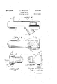
- Fig. 1 is a perspective view of a pair of handles in position at the ends f a control lever cross plece;
- Fig. 2 is a longitudinal transverse section through one of the handles on line 2-2 of Fig. 1;
- Fig. 3 is a fragmentary cross section through the upper end of a handle on line 3-3 of Fig. 2 with parts broken away;
- Fig. 4 is a side elevation View of a handle provided with a dead mans switch
- Fig. 5 is an inner face view of said handle provided with operating switches at both sides;
- Fig. 6 is a top plan view
- Fig. 7 is a bottom view of said handle.
- the handle I0 includes a body II formed from a case I2 and a cover I3, detachably connected and enclosing the operating parts.
- the body II is contoured to provide Aa downwardly extending grip portion I4, a head I5 and a mounting socket I6 which may be mounted on either end of conset screwsy I8.
- Thei case, I 21 (Fig. ,2); is advantageously formed ofmolded or cast ⁇ synthetic resin.
- the mounting socket. IB may, beofimetal, and may be fixed in place ⁇ in the case atthefmoldingor casting of the case. 'Ihey socket.. IB is provided. with a central passage ,Y I which .communicates with theinterior of the case .and with-.theeendioi hollow cross piece II, forprovidinga conduit through which thelead wires may extend from the handle 1 through the control ⁇ lever,
- the cover I3 iszdetachably, mounted on case I2 by screws 2-2; andthe inneriaces of the cover and case I2 are suitably hollowed out to form a spaceor. spacesin which the switches, leads andl operating levers or triggers may be located.
- a central ⁇ compartment 23 is provided, extending. into both. the casel2 and cover I3.
- One operatingswitchis advantageously located at the side of the head'. I5 where-it may be operated by the index finger oi the gunner if the switch isatthe. rear of the handle, ⁇ and by the thumb. ofthe ⁇ gunner if the. switch is in front.
- the cover I3 is provided with openingsll at both the front andthe back of the head f5, each adapted toreceive a finger pieceor trigger 25.
- the hger piece 25 is provided adjacent onev endv with laterally extending pivot studs 26 which rotatably fit in alignedsockets 2.1 formed incontiguous portions of the case I2' and cover I3;
- Aisuitableswitch 28 is mounted in case I2, as by screws 29', in register with the nger piece 25.
- the opposite ends 3S' of opening 24 advantageously converge toward the outside of the handle, overlying the ends of finger piece 25 and providing a stop for the free end thereof which is normally pressed outwardly by spring pressure from switch 28.
- switch and iinger piece construction may be employed.
- the form illustrated is a finger piece 25 whose free end face 3l registers with the adjacent end 30 of opening 24 and is provided with a transverse projection 32 which merges with the outer face 33 of the finger piece and is shaped for ready and comfortable engagement by the gunners iinger.
- a knob 34 extends inwardly from the iinger piece into position for engagement with a spring pressed actuating element (not shown) of switch 28.
- the symmetrical opening 24 on the opposite side of the handle head I5, as shown in Figs. 1-3, is provided.
- This opening may be closed by a ller block 35 which snugly ts the opening.
- the filler I block 35 is desirably held in place by retaining studs 33 which are provided at opposite sides of 1 the block adjacent each end thereof, and which fit into opposed pairs of sockets 21 formed in the case I2 and in the cover I3, respectively.
- the f i case I2 is provided with switch mounts 31 adja- -bas cent end openings, 24. With this arrangement a switch 28 and its finger piece 25 may be located ment illustrated in Figs. 4-7.
- The/ringer piece 25 may likewise be positioned with the projection i 32 at either end of opening 24 by'locatingthe pivot studs 26 in the appropriate alignedk pair of sockets 21, and by mounting switch28 inthe proper position relative toY nger piece 25.
- l switch construction of the latter type isillustrated in Figs. 1, 2, 4, 6 and '7, and is arranged vfor use as a dead mans switch, of the type which cuts out of operation appropriate parts of the apparatus controlled from the handle when the switch is not in operation by the hand of the gunner.
- a switch l may be mounted at each side as in the arrangeresins, though they can likewise be made in other ways and from other materials, such as wood or ⁇ metaL'with the provision of suitable insulation where necessary.
- a control handle including, in combination,V a hand-fitting body, a switch construction including a digitally operable actuating member, a
- a coil spring l 4l on one of the pivot studs42 has an innerY end 48 bearing against the interior of case I2 and a I ets formed in lugs 46 on cover I3.
- the lugs 45 extend into case I2 into register with bosses and by the body adjacent to eachA opening, a removable ller for an unused opening, and mounting elements on lthe Vfiller for cooperating with said mounting elements on the body.
- a hand grip handle and switch assembly adapted, distinctively for use'by one hand of an operator but fully convertible into a mirror image assembly adapted distinctively for use by the other hand of the operator; said assembly comprising a handle casing composed of separable complehook shaped outerend 49 extending around the i l adjacentl lower face of lever4l, arrangedV to bias said lever upwardly.
- a suitable switch 52 is mounted on boss A53 in '40 the caseV I2, and is engaged by a lug 54 on lever li! bearing against a Yspring pressed operating element (not shown) of the switch, the coil spring 4'! being of suflicient strength to throw the switch by the pressure of lug 54 against said element.
- lever 4I The outer end of lever 4I is located for engagement by the lower edge of the gunners hand,
- the parts including tlcecaseY I2, cover I3, linger piece 25, ller block 35 and lever 4I are adapted for construction from molded or cast synthetic recesses at either side ofthe mentary casing sections, each of symmetrical.
Landscapes
- Engineering & Computer Science (AREA)
- General Engineering & Computer Science (AREA)
- Switches With Compound Operations (AREA)
Description
April 2, 1946.- ARCULARIUS 2,397,828
CONTROL HANDLE Filed Feb'. 1'1, 194s 2 sheets-sheet 1 2 I IVENTOR.
Chazjes Aram/as 44 ATTORNEYS v April 2, 1946, c. ARcULARlUs 2,397,828
f CONTROL HANDLE f Filed FebQll, 194:5 2 sheets-sheet 2 INVENTOR.
ATTORNEYS Charles Azzzlaz'zzs y parts by. slight rearrangement thereof.
Patented Apr. 2, 1946 unir-ea stares PATE Nr i CONTROL HANDLE Charles ,-Arcnlarus, .New Canaan,l Conn., assgnon. by mesne assignments, to The Ii. Maxson Corporati'omNew'Yoi-k, N; Y., a vcorporation-ofA` Application.v February 11, 1943, Serial-No. 475,591
( Cl; 20u-157)' ZGlaims.
This invention-relates to.- control handles for electricallyy controlled guns and .isfespeciallyf suit.- able.1oruse in: connectionY with gun training and iing systemsof the typeemployedu in turrets. Such .systemsmay includea ,control lever. having a. cross `bar provided with control handles at its ends, which-carry, controlswitches. for various electrically operated devices, including firing triggers, intercommunication system switches andthe. like.. Inview,ofLtheiactthat .the handles are.V advantageously contoured` to provide. arm andi comfortable grip. fitting.l the. hand, and the switches must be locatedj for operation by the proper 'ngers, the l0cati0n.,.of` such switches on the left' handle is necessarily the` reverseot that employed on. theright handle.. Consequently it been necessary tdemploy, different designs for the two handles andjto. manufacture themseparately.
Thegeneralj. purpose ofthe inventionis to provide improvementsV in the. general. construction andV arrangementoihandles of, the indicated type. One. feature of theinvention; is the provision of a construction.whichemployesthesame parts for both handles.arrangedsothateither a right or a left handle. maybegassembled from the same Another feature` is to` provide:` ay simplevand, strong. construction which. can be; manufactured readily from synthetic. resins orothermaterialsA adapted for casting or molding.
Other objects. andsadvantages.V will.- appear. from the following description consideredinconnection withfthefaccompanyingdrawings in which:
Fig. 1 is a perspective view of a pair of handles in position at the ends f a control lever cross plece;
Fig. 2 is a longitudinal transverse section through one of the handles on line 2-2 of Fig. 1;
Fig. 3 is a fragmentary cross section through the upper end of a handle on line 3-3 of Fig. 2 with parts broken away;
Fig. 4 is a side elevation View of a handle provided with a dead mans switch;
Fig. 5 is an inner face view of said handle provided with operating switches at both sides;
Fig. 6 is a top plan view; and
Fig. 7 is a bottom view of said handle.
The handle I0 includes a body II formed from a case I2 and a cover I3, detachably connected and enclosing the operating parts. The body II is contoured to provide Aa downwardly extending grip portion I4, a head I5 anda mounting socket I6 which may be mounted on either end of conset screwsy I8.
Thei case, I 21 (Fig. ,2); is advantageously formed ofmolded or cast` synthetic resin. The mounting socket. IB may, beofimetal, and may be fixed in place` in the case atthefmoldingor casting of the case. 'Ihey socket.. IB is provided. with a central passage ,Y I which .communicates with theinterior of the case .and with-.theeendioi hollow cross piece II, forprovidinga conduit through which thelead wires may extend from the handle 1 through the control` lever,
The cover I3 iszdetachably, mounted on case I2 by screws 2-2; andthe inneriaces of the cover and case I2 are suitably hollowed out to form a spaceor. spacesin which the switches, leads andl operating levers or triggers may be located. In the form illustrated a central` compartment 23 is provided, extending. into both. the casel2 and cover I3.
One operatingswitchis advantageously located at the side of the head'. I5 where-it may be operated by the index finger oi the gunner if the switch isatthe. rear of the handle,` and by the thumb. ofthe `gunner if the. switch is in front. The cover I3is provided with openingsll at both the front andthe back of the head f5, each adapted toreceive a finger pieceor trigger 25. In the illustrated form the hger piece 25`is provided adjacent onev endv with laterally extending pivot studs 26 which rotatably fit in alignedsockets 2.1 formed incontiguous portions of the case I2' and cover I3; Aisuitableswitch 28 is mounted in case I2, as by screws 29', in register with the nger piece 25.` The opposite ends 3S' of opening 24 advantageously converge toward the outside of the handle, overlying the ends of finger piece 25 and providing a stop for the free end thereof which is normally pressed outwardly by spring pressure from switch 28.
Various types of switch and iinger piece construction may be employed. The form illustrated is a finger piece 25 whose free end face 3l registers with the adjacent end 30 of opening 24 and is provided with a transverse projection 32 which merges with the outer face 33 of the finger piece and is shaped for ready and comfortable engagement by the gunners iinger. A knob 34 extends inwardly from the iinger piece into position for engagement with a spring pressed actuating element (not shown) of switch 28.
The symmetrical opening 24 on the opposite side of the handle head I5, as shown in Figs. 1-3, is provided. This opening may be closed by a ller block 35 which snugly ts the opening. The filler I block 35 is desirably held in place by retaining studs 33 which are provided at opposite sides of 1 the block adjacent each end thereof, and which fit into opposed pairs of sockets 21 formed in the case I2 and in the cover I3, respectively. The f i case I2 is provided with switch mounts 31 adja- -bas cent end openings, 24. With this arrangement a switch 28 and its finger piece 25 may be located ment illustrated in Figs. 4-7. The/ringer piece 25 may likewise be positioned with the projection i 32 at either end of opening 24 by'locatingthe pivot studs 26 in the appropriate alignedk pair of sockets 21, and by mounting switch28 inthe proper position relative toY nger piece 25. A
l switch construction of the latter type isillustrated in Figs. 1, 2, 4, 6 and '7, and is arranged vfor use as a dead mans switch, of the type which cuts out of operation appropriate parts of the apparatus controlled from the handle when the switch is not in operation by the hand of the gunner. f
In the construction illustrated (Fig. 2f) the case at either side of the body I or, if desired, a switch l may be mounted at each side as in the arrangeresins, though they can likewise be made in other ways and from other materials, such as wood or` metaL'with the provision of suitable insulation where necessary. Y Y
I have described what I believe to be the best embodimentsr of my invention. I do not wish, however, to be confined to the embodiments shown, but what I desire to cover by Letters Patent is set forth in the appended claims.
Y l. A control handle including, in combination,V a hand-fitting body, a switch construction including a digitally operable actuating member, a
' switch mounting construction within the body arranged 'to support the switch in either'of two e laterally symmetrical positions suitable for'ren- VderingV the handle, according to the choice of i switch mounting, distinctively arhandle Yfor right hand use or distinctively a handle for left hand use, said body having laterallysymmetrical openings for alternatively accommodating the switchactuating membenfmounting elements for theV i switch-actuating member Ycarried by said member I3 is provided with an opening 40 extending along the center line of its outer'face at theflower end of the grip portion I4. Aswitch lever 4I extends through opening 40 and is pivotally mounted.Y at
i its inner end by studs 42 which rotatably fit into semi-cylindrical sockets 43 formed in bosses 44 on case I2 and into registering semi-cylindrical sock- 44 when the body VI I is assembled. A coil spring l 4l on one of the pivot studs42 has an innerY end 48 bearing against the interior of case I2 and a I ets formed in lugs 46 on cover I3. The lugs 45 extend into case I2 into register with bosses and by the body adjacent to eachA opening, a removable ller for an unused opening, and mounting elements on lthe Vfiller for cooperating with said mounting elements on the body. Y
' 2i.V A hand grip handle and switch assembly adapted, distinctively for use'by one hand of an operator but fully convertible into a mirror image assembly adapted distinctively for use by the other hand of the operator; said assembly comprising a handle casing composed of separable complehook shaped outerend 49 extending around the i l adjacentl lower face of lever4l, arrangedV to bias said lever upwardly. f
A suitable switch 52 is mounted on boss A53 in '40 the caseV I2, and is engaged by a lug 54 on lever li! bearing against a Yspring pressed operating element (not shown) of the switch, the coil spring 4'! being of suflicient strength to throw the switch by the pressure of lug 54 against said element.
The outer end of lever 4I is located for engagement by the lower edge of the gunners hand,
` :which will depress the lever and release switch 52 when the hand is in normal position gripping handle I; but upon removal ofthe hand the spring 41 will move lever 4I upwardly `and, throw switch 52. Y
The parts including tlcecaseY I2, cover I3, linger piece 25, ller block 35 and lever 4I are adapted for construction from molded or cast synthetic recesses at either side ofthe mentary casing sections, each of symmetrical.
construction with respect Vto a transverse longitudinal median plane ofY symmetry, means for securing the casing sections to one another in predetermined relation, means within the casing for supporting a switch on either Side of said plane and with either end toward the operator, Y
of the casing'. A
7 y v CHARLES ARCULARIUS.
Priority Applications (1)
| Application Number | Priority Date | Filing Date | Title |
|---|---|---|---|
| US475591A US2397828A (en) | 1943-02-11 | 1943-02-11 | Control handle |
Applications Claiming Priority (1)
| Application Number | Priority Date | Filing Date | Title |
|---|---|---|---|
| US475591A US2397828A (en) | 1943-02-11 | 1943-02-11 | Control handle |
Publications (1)
| Publication Number | Publication Date |
|---|---|
| US2397828A true US2397828A (en) | 1946-04-02 |
Family
ID=23888269
Family Applications (1)
| Application Number | Title | Priority Date | Filing Date |
|---|---|---|---|
| US475591A Expired - Lifetime US2397828A (en) | 1943-02-11 | 1943-02-11 | Control handle |
Country Status (1)
| Country | Link |
|---|---|
| US (1) | US2397828A (en) |
-
1943
- 1943-02-11 US US475591A patent/US2397828A/en not_active Expired - Lifetime
Similar Documents
| Publication | Publication Date | Title |
|---|---|---|
| US3198922A (en) | Handle for pilot's lever | |
| US3142227A (en) | Guard for control member | |
| US2200322A (en) | Cautery handle | |
| US2453683A (en) | Safety for firearms | |
| US1878038A (en) | Sliding cover for automatic firearms | |
| US3153874A (en) | Hinged barrel firearm with trigger safety means | |
| US2550873A (en) | Toy repeating rubber band pistol | |
| US2397828A (en) | Control handle | |
| ES472169A1 (en) | Circuit breaker with manual release | |
| ES8505097A1 (en) | Barrel and interchangeable trigger plate locking device for shot guns | |
| US1333268A (en) | Rifle attachment for throwing liquid | |
| US2150288A (en) | Air pistol | |
| US3842526A (en) | Safety warning system for firearms | |
| US2747057A (en) | Switch mounting bracket for airplane control stick | |
| US2607148A (en) | Auxiliary trigger mechanism for firearms | |
| US2360818A (en) | Control handle | |
| US1564089A (en) | Archery device | |
| US2455978A (en) | Spring-actuated projector for game boards | |
| US2896323A (en) | Guide for electric clippers | |
| US2542600A (en) | Table service utensil | |
| US3613286A (en) | Revolver with double action | |
| US2565018A (en) | Hammer safety for firearms | |
| GB1140266A (en) | Improvements in or relating to remote control handgrips | |
| IL29593A (en) | Double-barrelled signal pistol | |
| US2455990A (en) | Safety device for firearms |