US20220242564A1 - Unmanned aerial vehicle - Google Patents
Unmanned aerial vehicle Download PDFInfo
- Publication number
- US20220242564A1 US20220242564A1 US17/660,257 US202217660257A US2022242564A1 US 20220242564 A1 US20220242564 A1 US 20220242564A1 US 202217660257 A US202217660257 A US 202217660257A US 2022242564 A1 US2022242564 A1 US 2022242564A1
- Authority
- US
- United States
- Prior art keywords
- airframe
- unmanned aerial
- aerial vehicle
- axis direction
- rotor
- Prior art date
- Legal status (The legal status is an assumption and is not a legal conclusion. Google has not performed a legal analysis and makes no representation as to the accuracy of the status listed.)
- Pending
Links
- 230000005540 biological transmission Effects 0.000 claims description 16
- 239000003381 stabilizer Substances 0.000 claims description 14
- 238000010586 diagram Methods 0.000 description 7
- 238000000034 method Methods 0.000 description 6
- 230000014509 gene expression Effects 0.000 description 1
- 238000012986 modification Methods 0.000 description 1
- 230000004048 modification Effects 0.000 description 1
Images


Classifications
-
- B—PERFORMING OPERATIONS; TRANSPORTING
- B64—AIRCRAFT; AVIATION; COSMONAUTICS
- B64C—AEROPLANES; HELICOPTERS
- B64C3/00—Wings
-
- B—PERFORMING OPERATIONS; TRANSPORTING
- B64—AIRCRAFT; AVIATION; COSMONAUTICS
- B64C—AEROPLANES; HELICOPTERS
- B64C39/00—Aircraft not otherwise provided for
- B64C39/02—Aircraft not otherwise provided for characterised by special use
- B64C39/024—Aircraft not otherwise provided for characterised by special use of the remote controlled vehicle type, i.e. RPV
-
- B—PERFORMING OPERATIONS; TRANSPORTING
- B64—AIRCRAFT; AVIATION; COSMONAUTICS
- B64U—UNMANNED AERIAL VEHICLES [UAV]; EQUIPMENT THEREFOR
- B64U20/00—Constructional aspects of UAVs
- B64U20/40—Modular UAVs
-
- B—PERFORMING OPERATIONS; TRANSPORTING
- B64—AIRCRAFT; AVIATION; COSMONAUTICS
- B64U—UNMANNED AERIAL VEHICLES [UAV]; EQUIPMENT THEREFOR
- B64U30/00—Means for producing lift; Empennages; Arrangements thereof
- B64U30/10—Wings
- B64U30/12—Variable or detachable wings, e.g. wings with adjustable sweep
- B64U30/14—Variable or detachable wings, e.g. wings with adjustable sweep detachable
-
- B—PERFORMING OPERATIONS; TRANSPORTING
- B64—AIRCRAFT; AVIATION; COSMONAUTICS
- B64C—AEROPLANES; HELICOPTERS
- B64C29/00—Aircraft capable of landing or taking-off vertically, e.g. vertical take-off and landing [VTOL] aircraft
- B64C29/02—Aircraft capable of landing or taking-off vertically, e.g. vertical take-off and landing [VTOL] aircraft having its flight directional axis vertical when grounded
-
- B—PERFORMING OPERATIONS; TRANSPORTING
- B64—AIRCRAFT; AVIATION; COSMONAUTICS
- B64C—AEROPLANES; HELICOPTERS
- B64C37/00—Convertible aircraft
-
- B—PERFORMING OPERATIONS; TRANSPORTING
- B64—AIRCRAFT; AVIATION; COSMONAUTICS
- B64U—UNMANNED AERIAL VEHICLES [UAV]; EQUIPMENT THEREFOR
- B64U10/00—Type of UAV
- B64U10/10—Rotorcrafts
- B64U10/13—Flying platforms
- B64U10/14—Flying platforms with four distinct rotor axes, e.g. quadcopters
-
- B—PERFORMING OPERATIONS; TRANSPORTING
- B64—AIRCRAFT; AVIATION; COSMONAUTICS
- B64U—UNMANNED AERIAL VEHICLES [UAV]; EQUIPMENT THEREFOR
- B64U30/00—Means for producing lift; Empennages; Arrangements thereof
- B64U30/20—Rotors; Rotor supports
- B64U30/29—Constructional aspects of rotors or rotor supports; Arrangements thereof
- B64U30/291—Detachable rotors or rotor supports
-
- B64C2201/021—
-
- B64C2201/027—
-
- B64C2201/088—
-
- B—PERFORMING OPERATIONS; TRANSPORTING
- B64—AIRCRAFT; AVIATION; COSMONAUTICS
- B64C—AEROPLANES; HELICOPTERS
- B64C2211/00—Modular constructions of airplanes or helicopters
-
- B—PERFORMING OPERATIONS; TRANSPORTING
- B64—AIRCRAFT; AVIATION; COSMONAUTICS
- B64U—UNMANNED AERIAL VEHICLES [UAV]; EQUIPMENT THEREFOR
- B64U10/00—Type of UAV
- B64U10/20—Vertical take-off and landing [VTOL] aircraft
-
- B—PERFORMING OPERATIONS; TRANSPORTING
- B64—AIRCRAFT; AVIATION; COSMONAUTICS
- B64U—UNMANNED AERIAL VEHICLES [UAV]; EQUIPMENT THEREFOR
- B64U30/00—Means for producing lift; Empennages; Arrangements thereof
- B64U30/40—Empennages, e.g. V-tails
Definitions
- the present application relates to the field of unmanned aerial vehicles, and in particular, to an unmanned aerial vehicle.
- a vertical take-off and landing fixed-wing unmanned aerial vehicle may achieve properties of vertical take-off and landing and enduring flight with a fixed wing by using a vertical take-off and landing system and a propulsion system, so that the vertical take-off and landing fixed-wing unmanned aerial vehicle may take off and land on any terrain and fly quickly through the fixed wing to perform long-endurance flight missions.
- a vertical take-off and landing fixed-wing unmanned aerial vehicle has weak wind resistance due to the large-sized fixed wing.
- a multi-rotor unmanned aerial vehicle may vertically take off and land by using a rotor system and may fly in all directions by changing a rotation speed difference between rotors.
- the multi-rotor unmanned aerial vehicle has strong wind resistance but has short endurance and a low flight speed.
- embodiments of the present application provide an unmanned aerial vehicle that can switch between a vertical take-off and landing fixed-wing unmanned aerial vehicle and a multi-rotor unmanned aerial vehicle.
- An unmanned aerial vehicle including: an airframe; and a fixed-wing assembly and a rotor assembly, both replaceably connected to the airframe, where the fixed-wing assembly is connected to the airframe to form a vertical take-off and landing fixed-wing unmanned aerial vehicle and the rotor assembly is connected to the airframe to form a multi-rotor unmanned aerial vehicle.
- the airframe extends in a roll axis direction and includes a vehicle head, a vehicle body and a vehicle tail sequentially arranged in the roll axis direction.
- first rotor motors are disposed on a side of the airframe in a yaw axis direction of the airframe; and a rotary shaft of the first rotor motor extends in the yaw axis direction.
- two first rotor motors are disposed on the side of the airframe in the yaw axis direction of the airframe; and one of the first rotor motors is disposed at the vehicle head or at a position on the vehicle body close to the vehicle head and the other first rotor motor is disposed at the vehicle tail or at a position on the vehicle body close to the vehicle tail.
- two antennas are further disposed on the side on which the first rotor motors are disposed in the yaw axis direction of the airframe; and the two antennas and the two first rotor motors are all arranged in the roll axis direction and the antennas and the first rotor motors are disposed alternately.
- a lower vertical stabilizer is disposed on an other side of the airframe facing away from the first rotor motors in the yaw axis direction of the airframe; and the lower vertical stabilizer is disposed at the vehicle tail.
- a landing gear is further disposed on the other side of the airframe facing away from the first rotor motors in the yaw axis direction of the airframe; and the landing gear includes two support portions and the two support portions and the lower vertical stabilizer are jointly configured to support the airframe.
- the airframe includes two first mounting portions respectively disposed on two sides of the airframe in a pitch axis direction of the airframe;
- the rotor assembly includes two arm components, where each arm component includes a first assembling portion, the first assembling portion being configured to be connected to a corresponding second mounting portion;
- the fixed-wing assembly includes two side wing components, where each side wing component includes a second assembling portion, the second assembling portion being configured to be connected to a corresponding first mounting portion.
- the each arm component further includes an arm body and a second rotor motor; and an end of the arm body is connected to the first assembling portion and an other end of the arm body is connected to the second rotor motor.
- the arm body extends in the pitch axis direction.
- a rotary shaft of the second rotor motor extends in the yaw axis direction.
- a second propeller is mounted on the rotary shaft of the second rotor motor; a first propeller is mounted on the rotary shaft of the first rotor motor; and a size of the second propeller is equal to a size of the first propeller.
- the each side wing component further includes a side wing body, a wingtip and a third rotor motor; an end of the side wing body is connected to the second assembling portion, an other end of the side wing body is connected to the wingtip and the third rotor motor is mounted on the wingtip; and the wingtip is rotatable relative to the side wing body around the pitch axis direction.
- a rotary shaft of the third rotor motor is perpendicular to the pitch axis direction.
- the side wing body extends in the pitch axis direction.
- a third propeller is mounted on a rotary shaft of the third rotor motor; a first propeller is mounted on the rotary shaft of the first rotor motor; and a size of the third propeller is less than a size of the first propeller.
- each first mounting portion includes a first mounting surface and connecting rods formed on the first mounting surface, the first mounting surface facing away from the vehicle body, the connecting rods extending in the pitch axis direction; and either of each first assembling portion and each second assembling portion includes a first assembling surface, a first side surface and eccentric wheels, where the first assembling surface is configured to be attached to the first mounting surface and connecting holes are formed on the first assembling surface, the connecting holes being configured to be inserted by the connecting rods; the first side surface is adjacent to the first assembling surface and rotating holes are formed on the first side surface, the rotating hole including a rotation axis, the rotation axis being perpendicular to the pitch axis direction; and the eccentric wheels are mounted in the rotating holes and are rotatable in the rotating holes around the rotation axis, and the eccentric wheels are configured to lock the connecting rods to limit movement of the connecting rods in the pitch axis direction away from the eccentric wheels.
- the each first mounting portion further includes positioning beams formed on the first mounting surface and extending in the pitch axis direction, a cross-section of the positioning beam being non-circular; and positioning holes are further formed on the first assembling surface, the positioning holes matching the positioning beams and being configured to be inserted by the positioning beams.
- the each first mounting portion further includes a first plug-connection terminal disposed on the first mounting surface; and either of the each first assembling portion and the each second assembling portion further includes a second plug-connection terminal configured to be plug-connected to the first plug-connection terminal.
- the first mounting portion is plug-connected to and is fixed, by using a threaded fastener, to the first assembling portion and/or the second assembling portion.
- the unmanned aerial vehicle further includes a tail wing assembly detachably connected to the airframe; and both the lower vertical stabilizer and the fixed-wing assembly are connected to the airframe to form the vertical take-off and landing fixed-wing unmanned aerial vehicle.
- the tail wing assembly is rotatable relative to the airframe around the pitch axis direction when the tail wing assembly is connected to the airframe.
- two second mounting portions are disposed on the airframe; the two second mounting portions are respectively disposed on two sides of the airframe in the pitch axis direction of the airframe, each of the second mounting portions includes a second mounting surface, and a shaft hole and an arc-shaped guide hole are jointly formed on the two second mounting portions, both the shaft hole and the arc-shaped guide hole passing through second mounting surfaces of the two second mounting portions, the shaft hole being provided in the pitch axis direction and the arc-shaped guide hole being provided around the shaft hole; the tail wing assembly includes a rotary shaft, a transmission shaft and two tail wing components; and the rotary shaft is configured to be inserted into the shaft hole and has two ends both exposed outside the shaft hole; the transmission shaft is configured to be inserted into the arc-shaped guide hole and has two ends both exposed outside the arc-shaped guide hole; each tail wing component includes a second assembling surface for being in contact with a second mounting surface of a corresponding second mounting portion, a first plug-connection hole and a second
- the fixed-wing assembly and the rotor assembly are replaceably connected to the airframe, so that the fixed-wing assembly is connected to the airframe to form the vertical take-off and landing fixed-wing unmanned aerial vehicle, and the rotor assembly is connected to the airframe to form the multi-rotor unmanned aerial vehicle, thereby implementing an unmanned aerial vehicle that can switch between the vertical take-off and landing fixed-wing unmanned aerial vehicle and the multi-rotor unmanned aerial vehicle.
- FIG. 1 is a schematic structural diagram of an unmanned aerial vehicle in a configuration of a multi-rotor unmanned aerial vehicle according to an embodiment of the present application.
- FIG. 2 is a schematic exploded view of the multi-rotor unmanned aerial vehicle shown in FIG. 1 .
- FIG. 3 is a schematic structural diagram of an unmanned aerial vehicle in a configuration of a vertical take-off and landing fixed-wing unmanned aerial vehicle according to an embodiment of the present application.
- FIG. 4 is a schematic exploded view of the vertical take-off and landing fixed-wing unmanned aerial vehicle shown in FIG. 3 .
- FIG. 5 is a schematic structural diagram of an airframe of the multi-rotor unmanned aerial vehicle shown in FIG. 1 or the vertical take-off and landing fixed-wing unmanned aerial vehicle shown in FIG. 3 .
- FIG. 6 is a first partial view of the airframe shown in FIG. 5 , which mainly shows one first mounting portion of the airframe.
- FIG. 7 is a partial view of the first mounting portion shown in FIG. 5 , which mainly shows one connecting rod of the first mounting portion.
- FIG. 8 is a second partial view of the airframe shown in FIG. 6 , which mainly shows two first mounting portions of the airframe.
- FIG. 9 is a third partial view of the airframe shown in FIG. 5 , which mainly shows one second mounting portion of the airframe.
- FIG. 10 is a fourth partial view of the airframe shown in FIG. 8 , which mainly shows two second mounting portions of the airframe.
- FIG. 11 is a schematic structural diagram of a rotor assembly of the multi-rotor unmanned aerial vehicle shown in FIG. 2 .
- FIG. 12 is a partial view of one arm component of the rotor assembly shown in FIG. 11 , which mainly shows a first assembling portion of the arm component.
- FIG. 13 is a cross-sectional view of the first assembling portion of the rotor assembly shown in FIG. 12 , which mainly shows a rotating hole, an eccentric wheel and a closure cover of the first assembling portion.
- FIG. 14 is a schematic structural diagram of the eccentric wheel shown in FIG. 13 .
- FIG. 15 is a schematic structural diagram of a fixed-wing assembly of the vertical take-off and landing fixed-wing unmanned aerial vehicle shown in FIG. 4 , where a third rotor motor of the fixed-wing assembly is located at a first position.
- FIG. 16 is a three-dimensional view of one side wing component of the fixed-wing assembly shown in FIG. 15 , where the third rotor motor of the side wing component is located at a second position.
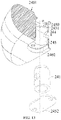
- FIG. 17 is a schematic structural diagram of a tail wing assembly of the vertical take-off and landing fixed-wing unmanned aerial vehicle shown in FIG. 4 .
- FIG. 1 to FIG. 4 show an unmanned aerial vehicle 100 provided in an embodiment of the present application.
- the unmanned aerial vehicle 100 includes an airframe 10 , a rotor assembly 20 , a fixed-wing assembly 30 and a tail wing assembly 40 .
- the rotor assembly 20 and the fixed-wing assembly 30 are replaceably connected to the airframe 10 .
- the tail wing assembly 40 is detachably connected to the airframe 10 .
- the rotor assembly 20 and the airframe 10 jointly form a multi-rotor unmanned aerial vehicle when the rotor assembly 20 is connected to the airframe 10 .
- the multi-rotor unmanned aerial vehicle is shown in FIG. 1 .
- the fixed-wing assembly 30 , the tail wing assembly 40 and the airframe 10 jointly form a vertical take-off and landing fixed-wing unmanned aerial vehicle when both the fixed-wing assembly 30 and the tail wing assembly 40 are connected to the airframe 10 .
- the vertical take-off and landing fixed-wing unmanned aerial vehicle is shown in FIG. 3 .
- the airframe 10 is strip-shaped in a roll axis direction y as a whole and includes a vehicle head 11 , a vehicle body 12 and a vehicle tail 13 sequentially arranged in the roll axis direction y.
- a circuit module (not shown in the figure) is configured in the airframe 10 .
- the circuit module includes a circuit board and a plurality of electronic components mounted on the circuit board.
- the circuit module is mainly configured to control electronic devices disposed outside the airframe 10 and the rotor assembly 20 or the fixed-wing assembly 30 connected to the airframe 10 .
- the electronic devices disposed outside the airframe 10 include two first rotor motors 14 and two antennas 15 .
- the two first rotor motors 14 and the two antennas 15 are all disposed on a same side of the airframe 10 in a yaw axis direction z of the airframe.
- One of the first rotor motors 14 is disposed on the vehicle head 11 or at a position on the vehicle body 12 close to the vehicle head 11 .
- the other rotor motor 14 is disposed on the vehicle tail 13 or at a position on the vehicle body 12 close to the vehicle tail 13 .
- the two first rotor motors 14 are configured to jointly provide lift.
- a rotary shaft of each first rotor motor 14 is disposed in the yaw axis direction z and a first propeller (not shown in the figure) is mounted on the rotary shaft.
- a quantity of first rotor motors is not limited to 2, which may be set according to an actual condition.
- the quantity of first rotor motors may be smaller if the airframe has less load or the airframe is lighter; and the quantity of first rotor motors may be larger if the airframe has more load or the airframe is heavier.
- the two first rotor motors 14 and the two antennas 15 are all arranged in the roll axis direction y.
- the antennas 15 and the first rotor motors 14 are disposed alternately.
- the two antennas 15 are configured to jointly perform navigation and positioning for the unmanned aerial vehicle.
- Each antenna 15 may be a real-time kinematic (RTK) antenna.
- RTK real-time kinematic
- a quantity of antennas is not limited to 2, which may be more or less according to an actual condition.
- a lower vertical stabilizer 16 , a landing gear 17 , two first mounting portions 18 and two second mounting portions 19 are further disposed outside the airframe 10 .
- Both the lower vertical stabilizer 16 and the landing gear 17 are disposed on an other side of the airframe 10 facing away from the two first rotor motors 14 in the yaw axis direction z of the airframe.
- the lower vertical stabilizer 16 is disposed at the vehicle tail 13 .
- the landing gear 17 is disposed at the vehicle body 12 .
- the landing gear 17 includes two support portions 170 .
- the two support portions 170 are inversely splayed and configured to support the airframe 10 together with the lower vertical stabilizer 16 .
- the two first mounting portions 18 are respectively disposed on two sides of the vehicle body 12 in a pitch axis direction x of the vehicle body.
- the two second mounting portions 19 are respectively disposed on two sides of the vehicle tail 13 in a pitch axis direction x of the vehicle tail.
- the first mounting portion 18 includes a first mounting body 180 , two connecting rods 181 , a positioning beam 182 and a first plug-connection terminal 183 .
- the first mounting body 180 is disposed on a side of the vehicle body 12 in the pitch axis direction x of the vehicle body and includes a first mounting surface 1800 .
- the first mounting surface 1800 is disposed facing away from the vehicle body 12 .
- the two connecting rods 181 , the positioning beam 182 and the first plug-connection terminal 183 are all formed on the first mounting surface 1800 .
- Each connecting rod 181 extends in the pitch axis direction x.
- the positioning beam 182 extends in the pitch axis direction x and has a hollow square cross-section. According to an actual condition, a cross-section of the positioning beam may alternatively be designed into any other non-circular shape such as an ellipse, a triangle or a pentagon.
- the first plug-connection terminal 183 is electrically connected to the circuit module.
- the connecting rod 181 includes a base 1810 , a rod body 1811 and a limiting body 1812 .
- the base 1810 is formed on the first mounting surface 1800 .
- the rod body 1811 extends in the pitch axis direction x and has one end connected to the base 1810 and an other end connected to the limiting body 1812 .
- a cross-section size of the rod body 1811 is less than a cross-section size of the limiting body 1812 .
- the limiting body 1812 is spherical. According to an actual condition, the limiting body 1812 may be in any shape as long as the cross-section size of the limiting body is greater than the cross-section size of the rod body 1811 .
- a cross beam 184 passes through first mounting surfaces 1800 of two first mounting portions 18 .
- Positioning beams 182 of the two first mounting portions 18 are respectively formed at two ends of the cross beam 184 .
- the positioning beams 182 and the first mounting body 180 may alternatively be integrally formed.
- each second mounting portion 19 includes a second mounting surface 190 .
- the second mounting surface 190 is disposed facing away from the vehicle tail 13 .
- a shaft hole 191 and an arc-shaped guide hole 192 are jointly formed on two second mounting portions 19 . Both the shaft hole 191 and the arc-shaped guide hole 192 pass through the second mounting surfaces 190 of the two second mounting portions 19 . Both the shaft hole 191 and the arc-shaped guide hole 192 extend in the pitch axis direction x.
- the arc-shaped guide hole 192 is provided around the shaft hole 191 .
- the rotor assembly 20 includes arm components 21 .
- a quantity of arm components 21 corresponds to a quantity of first mounting portions 18 .
- Each arm component 21 is configured to be connected to a corresponding first mounting portion 18 .
- the arm component 21 includes an arm body 22 , a second rotor motor 23 and a first assembling portion 24 .
- the arm body 22 extends in the pitch axis direction x.
- One end of the arm body 22 is connected to the second rotor motor 23 and an other end of the arm body 22 is connected to the first assembling portion 24 .
- the arm body 22 is hollow for wiring of the second rotor motor 23 , to electrically connect the second rotor motor 23 to the first assembling portion 24 .
- a rotary shaft of the second rotor motor 23 is disposed in the yaw axis direction z and a second propeller (not shown in the figure) is mounted on the rotary shaft.
- the second rotor motor 23 is configured to provide lift.
- the first assembling portion 24 is configured to be connected to a corresponding first mounting portion 18 .
- the first assembling portion 24 includes an first assembling body 240 , eccentric wheels 241 and a second plug-connection terminal 242 .
- the first assembling body 240 includes a first assembling surface 2400 , a first side surface 2401 and a second side surface 2402 .
- the first side surface 2401 is opposite to the second side surface 2402 .
- the first assembling surface 2400 is connected between the first side surface 2401 and the second side surface 2402 .
- the first assembling surface 2400 is configured to be attached to the first mounting surface 1800 of the first mounting portion 18 .
- Positioning holes 243 and connecting holes 244 are formed on the first assembling surface 2400 .
- the positioning holes 243 match the positioning beam 182 of the first mounting portion 18 and are configured to be inserted by the positioning beam 182 .
- a quantity of connecting holes 244 corresponds to a quantity of connecting rods 181 .
- Each connecting hole 244 is configured to be inserted by a corresponding connecting rod 181 .
- Rotating holes 245 are formed on the first side surface 2401 .
- a quantity of rotating holes 245 corresponds to the quantity of connecting holes 244 .
- the second plug-connection terminal 242 is disposed on the first assembling surface 2400 .
- the second plug-connection terminal 242 of the arm component 21 is electrically connected to the second rotor motor 23 .
- the rotating hole 245 includes a rotation axis o, the rotation axis o is set perpendicular to the pitch axis direction x and the rotating hole 245 is in communication with a corresponding connecting hole 244 .
- the rotating hole 245 extends from the first side surface 2401 to the second side surface 2402 .
- a hole wall of the rotating hole 245 includes an annular stopper portion 2450 protruding close to the first side surface 2401 .
- the annular stopper portion 2450 is disposed around the rotation axis o and includes an arc-shaped bump 2451 protruding toward the second side surface 2402 .
- the arc-shaped bump 2451 is disposed around the rotation axis o.
- An opening of the rotating hole 245 on the second side surface 2402 is closed by a closure plate 2452 .
- the closure plate 2452 may be fixed on the second side surface 2402 by using a threaded fastener.
- a quantity of eccentric wheels 241 corresponds to the quantity of rotating holes 245 .
- Each eccentric wheel 241 is mounted in a corresponding rotating hole 245 for locking a corresponding connecting rod 181 .
- the eccentric wheel 241 includes a rotating wheel 2410 , a boss 2411 and an interference portion 2412 .
- the rotating wheel 2410 is disposed around the rotation axis o.
- a cavity 2413 is formed in the rotating wheel 2410 and used for accommodating the limiting body 1812 .
- the rotating wheel 2410 includes a first end surface 2414 , a second end surface 2415 and a cylindrical surface 2416 .
- the first end surface 2414 is opposite to the second end surface 2415 .
- the cylindrical surface 2416 is disposed around the rotation axis o and is connected between the first end surface 2414 and the second end surface 2415 .
- An arc-shaped guide groove 2417 and an avoidance groove 2418 are formed on the cylindrical surface 2416 .
- the arc-shaped guide groove 2417 is in communication with the cavity 2413 and is provided around the rotation axis o.
- the arc-shaped guide groove 2417 includes a first end and a second end.
- the arc-shaped guide groove 2417 is configured for the rod body 1811 to rotate along the arc-shaped guide groove 2417 around the rotation axis o and is configured to prevent the limiting body 1812 from moving in the pitch axis direction x.
- the avoidance groove 2418 is in communication with the cavity 2413 and a first end of the arc-shaped guide groove 2417 .
- the avoidance groove 2418 is configured for the limiting body 1812 to pass through.
- the boss is formed in the center of the first end surface 2414 .
- a groove 2419 configured to be screwed by a screwdriver is formed on a surface of the boss 2411 facing away from the first end surface 2414 .
- the groove 2419 is, for example, a straight line groove, a cross groove, a Torx groove or a hexagon socket groove and is a straight line groove in the figure.
- the boss 2411 includes an interference portion 2412 protruding in a direction perpendicular to the rotation axis o.
- the eccentric wheel 241 is inserted into the rotating hole 245 after the first end surface 2414 of the rotating wheel 2410 is aligned with an opening of the rotating hole 245 provided on the second side surface 2402 .
- the first end surface 2414 of the rotating wheel 2410 abuts against the arc-shaped bump 2451 and/or the interference portion 2412 abuts against the annular stopper portion 2450 ;
- the cylindrical surface 2416 is sleeved on the hole wall of the rotating hole 245 ;
- the connecting hole 244 in communication with the rotating hole 245 is aligned with the arc-shaped guide groove 2417 or the avoidance groove 2418 ; and fourthly, the boss 2411 is exposed from an opening of the rotating hole 245 provided on the first side surface 2401 .
- the closure plate 2452 is mounted on the second side surface 2402 .
- the closure plate 2452 abuts against the second end surface 2415 of the rotating wheel 2410 after the closure plate 2452 is mounted on the second side surface 2402 .
- the eccentric wheel 241 is mounted on the rotating hole 245 .
- the eccentric wheel 241 may only be rotated around the rotation axis o between a first rotation position and a second rotation position in the rotating hole 245 .
- An assembling relationship between the eccentric wheel 241 and the rotating hole 245 is described below to explain why the eccentric wheel 241 may only be rotated around the rotation axis o between the first rotation position and the second rotation position in the rotating hole 245 .
- the first end surface 2414 of the rotating wheel 2410 abuts against the arc-shaped bump 2451 and/or the interference portion 2412 abuts against the annular stopper portion 2450 ; and the second end surface 2415 of the rotating wheel 2410 abuts against the closure plate 2452 , so that degrees of freedom except two degrees of freedom of moving the eccentric wheel 241 in the direction perpendicular to the rotation axis o and one degree of freedom of rotating around the rotation axis o are limited.
- the cylindrical surface 2416 of the rotating wheel 2410 is sleeved on the hole wall of the rotating hole 245 , so that the two degrees of freedom of moving the eccentric wheel 241 in the direction perpendicular to the rotation axis o are further limited.
- the eccentric wheel 241 when the eccentric wheel 241 is rotated around the rotation axis o, the arc-shaped bump 2451 will stop the interference portion 2412 to prevent the eccentric wheel 241 from continuing to rotate. Based on the above, the eccentric wheel 241 may only be rotated around the rotation axis o between the first rotation position and the second rotation position in the rotating hole 245 . When the eccentric wheel 241 is rotated to the first rotation position, the interference portion 2412 abuts against an end of the arc-shaped bump 2451 and the avoidance groove 2418 is aligned with the connecting hole 244 .
- the interference portion 2412 abuts against an other end of the arc-shaped bump 2451 and a second end of the arc-shaped guide groove 2417 is aligned with the connecting hole 244 .
- the first mounting portion is connected to the first assembling portion.
- the positioning beam 182 is aligned with and inserted into the positioning hole 243 .
- each connecting rod 181 is automatically aligned with and inserted into a corresponding connecting hole 244 ; and secondly, the first plug-connection terminal 183 is automatically aligned with and plug-connected to the second plug-connection terminal 242 .
- the eccentric wheel 241 When the connecting rod 181 is inserted into the connecting hole 244 , the eccentric wheel 241 is rotated to the first rotation position and the avoidance groove 2418 of the eccentric wheel 241 is aligned with the connecting hole 244 .
- the limiting body 1812 of the connecting rod 181 sequentially passes through the connecting hole 244 and the avoidance groove 2418 .
- the connecting rod 181 After the connecting rod 181 is fully inserted into the connecting hole 244 , the limiting body 1812 of the connecting rod 181 is accommodated in the cavity 2413 of the eccentric wheel 241 and the rod body 1811 of the connecting rod 181 is located in the avoidance groove 2418 .
- each connecting rod 181 is also fully inserted into the corresponding connecting hole 244 ; secondly, the first plug-connection terminal 183 is also fully plug-connected to the second plug-connection terminal 242 ; and thirdly, the first mounting surface 1800 is in contact with the first assembling surface 2400 . Then, the eccentric wheel 241 is rotated to the second rotation position.
- the rod body 1811 is located at the second end of the arc-shaped guide groove 2417 of the eccentric wheel 241 . In this case, the rotor assembly 20 is connected to the airframe 10 .
- the positioning beam 182 is inserted into the positioning hole 243 , the positioning beam 182 and the positioning hole 243 are matched with each other and a cross-section of the positioning beam 182 is square. Therefore, other degrees of freedom except a degree of freedom of moving the arm component 21 in the pitch axis direction x are limited.
- the arc-shaped guide groove 2417 prevents the limiting body 1812 from retreating from the cavity 2413 and cooperates with the first mounting surface 1800 to abut against the first assembling surface 2400 , so that the degree of freedom of moving the arm component 21 in the pitch axis direction x is limited.
- the quantity of connecting rods 181 is not limited to 2, which may be set according to an actual condition. For example, if the airframe 10 is lighter or the airframe 10 has less load, the quantity of connecting rods 181 may be smaller, or otherwise, the quantity of connecting rods 181 may be larger.
- the first assembling portion of the arm component is plug-connected to and is fixed, by using a threaded fastener, to a corresponding first mounting portion.
- a specific working process of the multi-rotor unmanned aerial vehicle is as follows:
- Two first rotor motors 14 and second rotor motors 23 of two arm components 21 jointly work to provide lift for vertical take-off and landing of the multi-rotor unmanned aerial vehicle.
- the four rotor motors are differentially controlled to provide the multi-rotor unmanned aerial vehicle with pitch control, roll control, yaw control and omnidirectional flight.
- the lower vertical stabilizer 16 may further ensure stable yaw of the multi-rotor unmanned aerial vehicle.
- a size of the first propeller mounted on the first rotor motor 14 is equal to a size of the second propeller mounted on the second rotor motor 23 .
- designing the first propeller and the second propeller into propellers in large sizes may ensure vertical take-off and landing of the multi-rotor unmanned aerial vehicle with heavy load.
- the fixed-wing assembly 30 includes two side wing components 31 .
- the side wing component 31 includes a side wing body 32 , a wingtip 33 , a third rotor motor 34 , a tilt motor (not shown in the figure) and a second assembling portion 35 .
- the side wing body 32 extends in the pitch axis direction x.
- One end of the side wing body 32 is connected to the wingtip 33 and an other end of the side wing body 32 is connected to the second assembling portion 35 .
- the tilt motor is mounted on the side wing body 32 and is connected to the wingtip 33 .
- the third rotor motor 34 is mounted on the wingtip 33 .
- the wingtip 33 is rotatable relative to the side wing body 32 around the pitch axis direction x, so that the third rotor motor 34 mounted on the wingtip 33 is rotatable between a first tilt position and a second tilt position around the pitch axis direction x.
- the tilt motor is configured to drive the wingtip 33 to rotate around the pitch axis direction x.
- the wingtip 33 is substantially level with the side wing body 32 .
- the wingtip 33 is substantially orthogonal to the side wing body 32 .
- a rotary shaft of the third rotor motor 34 is disposed perpendicular to the pitch axis direction x and a third propeller (not shown in the figure) is mounted on the rotary shaft of the third rotor motor 34 .
- a third propeller (not shown in the figure) is mounted on the rotary shaft of the third rotor motor 34 .
- the rotary shaft of the third rotor motor 34 is substantially rotated in the roll axis direction y to provide thrust.
- the rotary shaft of the third rotor motor 34 is substantially rotated in the yaw axis direction z to provide lift.
- the second assembling portion 35 is configured to be connected to a corresponding first mounting portion 18 .
- a structure of the second assembling portion 35 is similar to a structure of the first assembling portion 24 .
- either of the second assembling portion 35 and the first assembling portion 24 includes a first first assembling body 240 , eccentric wheels 241 and a second plug-connection terminal 242 .
- the second plug-connection terminal 242 of the side wing component 31 is electrically connected to the tilt motor and the third rotor motor 34 .
- the first mounting portion is connected to the second assembling portion.
- a process of mounting the second assembling portion on the first mounting portion is similar to the process of mounting the first assembling portion on the first mounting portion because structures of the second assembling portion and the first assembling portion are similar. Details will not be repeated herein.
- the tail wing assembly 40 includes tail wing components 41 , a rotary shaft 42 and a transmission shaft 43 .
- a quantity of tail wing components 41 corresponds to a quantity of second mounting portions 19 .
- One of the tail wing components 41 is used as an example.
- the tail wing component 41 includes a second assembling surface 410 .
- the second assembling surface 410 is disposed substantially perpendicular to the pitch axis direction x.
- a first plug-connection hole 44 and a second plug-connection hole 45 are formed on the second assembling surface 410 . Both the first plug-connection hole 44 and the second plug-connection hole 45 are provided in the pitch axis direction x and are respectively configured to be plug-connected to an end of the rotary shaft 42 and an end of the transmission shaft 43 .
- a process of connecting the tail wing assembly 40 to the airframe 10 is described below.
- the rotary shaft 42 is inserted into the shaft hole 191 and has two ends both exposed outside the shaft hole 191 .
- the transmission shaft 43 is inserted into the arc-shaped guide hole 192 and has two ends both exposed outside the arc-shaped guide hole 192 .
- the first plug-connection hole 44 of each tail wing component 41 is configured to be inserted by an end of a corresponding rotary shaft 42 ; and further, the second plug-connection hole 45 of the each tail wing component 41 is configured to be inserted by an end of a corresponding transmission shaft 43 .
- the second assembling surface 410 of the each tail wing component 41 is in contact with a second mounting surface 190 of a corresponding second mounting portion 19 after the first plug-connection hole 44 of the each tail wing component 41 is fully inserted by the end of the corresponding rotary shaft 42 and the second plug-connection hole 45 of the each tail wing component 41 is fully inserted by the end of the corresponding transmission shaft 43 .
- the tail wing assembly 40 is connected to the airframe 10 .
- the transmission shaft 43 is rotated along the arc-shaped guide hole 192 around the pitch axis direction x to drive two tail wing components 41 to rotate around the rotary shaft 42 .
- a drive motor (not shown in the figure) configured to drive the transmission shaft 43 to rotate around the pitch axis direction x is disposed in the lower vertical stabilizer 16 .
- the drive motor is connected to the transmission shaft 43 by using a transmission mechanism such as a connecting rod.
- a specific working process of the vertical take-off and landing fixed-wing unmanned aerial vehicle is as follows:
- first rotor motors 14 provide lift and pitch control.
- Third rotor motors 34 of two side wing components 31 are tilted to the second tilt position to provide auxiliary lift.
- the third rotor motors 34 of the two side wing components 31 are differentially controlled and tilt motors of the two side wing components 31 are tilted and differentially controlled to provide roll control and yaw control.
- side wing bodies 32 of the two side wing components 31 provide lift and two tail wing components 41 provide pitch control.
- the third rotor motors 34 of the two side wing components 31 are tilted to the first tilt position to provide thrust.
- the third rotor motors 34 of the two side wing components 31 are differentially controlled and tilt motors of the two side wing components 31 are tilted and differentially controlled to provide roll control and yaw control.
- the fixed-wing assembly 30 and the rotor assembly 20 are replaceably connected to the airframe 10 , the fixed-wing assembly 30 is connected to the airframe 10 to form the vertical take-off and landing fixed-wing unmanned aerial vehicle and the rotor assembly 20 is connected to the airframe 10 to form the multi-rotor unmanned aerial vehicle, thereby implementing an unmanned aerial vehicle that can switch between the vertical take-off and landing fixed-wing unmanned aerial vehicle and the multi-rotor unmanned aerial vehicle.
Landscapes
- Engineering & Computer Science (AREA)
- Aviation & Aerospace Engineering (AREA)
- Mechanical Engineering (AREA)
- Remote Sensing (AREA)
- Toys (AREA)
Applications Claiming Priority (3)
| Application Number | Priority Date | Filing Date | Title |
|---|---|---|---|
| CN201911014063.1 | 2019-10-23 | ||
| CN201911014063.1A CN110615097A (zh) | 2019-10-23 | 2019-10-23 | 一种无人飞行器 |
| PCT/CN2020/123316 WO2021078267A1 (fr) | 2019-10-23 | 2020-10-23 | Véhicule aérien sans pilote |
Related Parent Applications (1)
| Application Number | Title | Priority Date | Filing Date |
|---|---|---|---|
| PCT/CN2020/123316 Continuation WO2021078267A1 (fr) | 2019-10-23 | 2020-10-23 | Véhicule aérien sans pilote |
Publications (1)
| Publication Number | Publication Date |
|---|---|
| US20220242564A1 true US20220242564A1 (en) | 2022-08-04 |
Family
ID=68926688
Family Applications (1)
| Application Number | Title | Priority Date | Filing Date |
|---|---|---|---|
| US17/660,257 Pending US20220242564A1 (en) | 2019-10-23 | 2022-04-22 | Unmanned aerial vehicle |
Country Status (3)
| Country | Link |
|---|---|
| US (1) | US20220242564A1 (fr) |
| CN (1) | CN110615097A (fr) |
| WO (1) | WO2021078267A1 (fr) |
Cited By (3)
| Publication number | Priority date | Publication date | Assignee | Title |
|---|---|---|---|---|
| US20200290718A1 (en) * | 2017-12-07 | 2020-09-17 | SZ DJI Technology Co., Ltd. | Unmanned aerial vehicle |
| USD989686S1 (en) * | 2018-06-22 | 2023-06-20 | Transcend Air Corporation | Vertical take-off and landing tilt-wing passenger aircraft |
| USD997073S1 (en) * | 2021-06-22 | 2023-08-29 | Transcend Air Corporation | Vertical take-off and landing tilt-wing passenger aircraft |
Families Citing this family (4)
| Publication number | Priority date | Publication date | Assignee | Title |
|---|---|---|---|---|
| CN110775248A (zh) * | 2019-10-21 | 2020-02-11 | 深圳市道通智能航空技术有限公司 | 一种无人机 |
| CN110615097A (zh) * | 2019-10-23 | 2019-12-27 | 深圳市道通智能航空技术有限公司 | 一种无人飞行器 |
| CN110615096A (zh) * | 2019-10-23 | 2019-12-27 | 深圳市道通智能航空技术有限公司 | 一种无人飞行器 |
| CN114044151A (zh) * | 2021-11-08 | 2022-02-15 | 中山福昆航空科技有限公司 | 一种无人机动力模块 |
Citations (14)
| Publication number | Priority date | Publication date | Assignee | Title |
|---|---|---|---|---|
| GB1009985A (en) * | 1961-12-22 | 1965-11-17 | Harold Kahan Warr Langton | Fastener for separably fastening parts together |
| US20060091258A1 (en) * | 2004-10-29 | 2006-05-04 | Chiu Tien S | Autonomous, back-packable computer-controlled breakaway unmanned aerial vehicle (UAV) |
| US7946528B2 (en) * | 2005-04-15 | 2011-05-24 | Urban Aeronautics, Ltd. | Flight control system especially suited for VTOL vehicles |
| US20160200436A1 (en) * | 2013-08-13 | 2016-07-14 | U.S.A. As Represented By The Administrator Of The National Aeronautics And Space Administration | Tri-Rotor Aircraft Capable of Vertical Takeoff and Landing and Transitioning to Forward Flight |
| US20160244160A1 (en) * | 2013-08-09 | 2016-08-25 | FourthWing Sensors, LLC | Convertible unmanned aerial vehicle |
| CN105939927A (zh) * | 2015-12-24 | 2016-09-14 | 深圳市大疆创新科技有限公司 | 快拆结构、多旋翼无人飞行器、组件及旋翼组件 |
| US20170001723A1 (en) * | 2015-06-30 | 2017-01-05 | Kabushiki Kaisha Topcon | Site management system, in-flight detection method, and non-transitory computer readable medium storing program of site management system |
| CN106965921A (zh) * | 2017-05-09 | 2017-07-21 | 嘉兴安行信息科技有限公司 | 固定翼与多旋翼一体无人飞机 |
| CN206984352U (zh) * | 2017-06-19 | 2018-02-09 | 昊翔电能运动科技(昆山)有限公司 | 可变型无人飞行器 |
| WO2018047187A1 (fr) * | 2016-09-12 | 2018-03-15 | Israel Aerospace Industries Ltd. | Système de véhicule modulaire |
| US20180273158A1 (en) * | 2017-03-22 | 2018-09-27 | Aurora Flight Sciences Corporation | Multi-Architecture Modular Unmanned Aerial System |
| CN109436314A (zh) * | 2018-12-29 | 2019-03-08 | 深圳市道通智能航空技术有限公司 | 一种无人飞行器 |
| CN209192222U (zh) * | 2018-12-03 | 2019-08-02 | 成都纵横大鹏无人机科技有限公司 | 一种飞行姿态可转换的无人机 |
| US20200010182A1 (en) * | 2015-11-07 | 2020-01-09 | Joseph Raymond RENTERIA | Pivoting wing system for vtol aircraft |
Family Cites Families (2)
| Publication number | Priority date | Publication date | Assignee | Title |
|---|---|---|---|---|
| CN110615097A (zh) * | 2019-10-23 | 2019-12-27 | 深圳市道通智能航空技术有限公司 | 一种无人飞行器 |
| CN110615096A (zh) * | 2019-10-23 | 2019-12-27 | 深圳市道通智能航空技术有限公司 | 一种无人飞行器 |
-
2019
- 2019-10-23 CN CN201911014063.1A patent/CN110615097A/zh active Pending
-
2020
- 2020-10-23 WO PCT/CN2020/123316 patent/WO2021078267A1/fr active Application Filing
-
2022
- 2022-04-22 US US17/660,257 patent/US20220242564A1/en active Pending
Patent Citations (15)
| Publication number | Priority date | Publication date | Assignee | Title |
|---|---|---|---|---|
| GB1009985A (en) * | 1961-12-22 | 1965-11-17 | Harold Kahan Warr Langton | Fastener for separably fastening parts together |
| US20060091258A1 (en) * | 2004-10-29 | 2006-05-04 | Chiu Tien S | Autonomous, back-packable computer-controlled breakaway unmanned aerial vehicle (UAV) |
| US7946528B2 (en) * | 2005-04-15 | 2011-05-24 | Urban Aeronautics, Ltd. | Flight control system especially suited for VTOL vehicles |
| US20160244160A1 (en) * | 2013-08-09 | 2016-08-25 | FourthWing Sensors, LLC | Convertible unmanned aerial vehicle |
| US20160200436A1 (en) * | 2013-08-13 | 2016-07-14 | U.S.A. As Represented By The Administrator Of The National Aeronautics And Space Administration | Tri-Rotor Aircraft Capable of Vertical Takeoff and Landing and Transitioning to Forward Flight |
| US20170001723A1 (en) * | 2015-06-30 | 2017-01-05 | Kabushiki Kaisha Topcon | Site management system, in-flight detection method, and non-transitory computer readable medium storing program of site management system |
| US20200010182A1 (en) * | 2015-11-07 | 2020-01-09 | Joseph Raymond RENTERIA | Pivoting wing system for vtol aircraft |
| CN105939927A (zh) * | 2015-12-24 | 2016-09-14 | 深圳市大疆创新科技有限公司 | 快拆结构、多旋翼无人飞行器、组件及旋翼组件 |
| WO2018047187A1 (fr) * | 2016-09-12 | 2018-03-15 | Israel Aerospace Industries Ltd. | Système de véhicule modulaire |
| US11603197B2 (en) * | 2016-09-12 | 2023-03-14 | Israel Aerospace Industries Ltd. | Modular vehicle system |
| US20180273158A1 (en) * | 2017-03-22 | 2018-09-27 | Aurora Flight Sciences Corporation | Multi-Architecture Modular Unmanned Aerial System |
| CN106965921A (zh) * | 2017-05-09 | 2017-07-21 | 嘉兴安行信息科技有限公司 | 固定翼与多旋翼一体无人飞机 |
| CN206984352U (zh) * | 2017-06-19 | 2018-02-09 | 昊翔电能运动科技(昆山)有限公司 | 可变型无人飞行器 |
| CN209192222U (zh) * | 2018-12-03 | 2019-08-02 | 成都纵横大鹏无人机科技有限公司 | 一种飞行姿态可转换的无人机 |
| CN109436314A (zh) * | 2018-12-29 | 2019-03-08 | 深圳市道通智能航空技术有限公司 | 一种无人飞行器 |
Cited By (3)
| Publication number | Priority date | Publication date | Assignee | Title |
|---|---|---|---|---|
| US20200290718A1 (en) * | 2017-12-07 | 2020-09-17 | SZ DJI Technology Co., Ltd. | Unmanned aerial vehicle |
| USD989686S1 (en) * | 2018-06-22 | 2023-06-20 | Transcend Air Corporation | Vertical take-off and landing tilt-wing passenger aircraft |
| USD997073S1 (en) * | 2021-06-22 | 2023-08-29 | Transcend Air Corporation | Vertical take-off and landing tilt-wing passenger aircraft |
Also Published As
| Publication number | Publication date |
|---|---|
| CN110615097A (zh) | 2019-12-27 |
| WO2021078267A1 (fr) | 2021-04-29 |
Similar Documents
| Publication | Publication Date | Title |
|---|---|---|
| US20220242564A1 (en) | Unmanned aerial vehicle | |
| US20220242563A1 (en) | Unmanned aerial vehicle | |
| US11459099B2 (en) | M-wing aircraft having VTOL and biplane orientations | |
| US11655023B2 (en) | Fixed-wing vertical take-off and landing hybrid UAV | |
| US10501193B2 (en) | Aircraft having a versatile propulsion system | |
| US10442522B2 (en) | Aircraft with active aerosurfaces | |
| US10661892B2 (en) | Aircraft having omnidirectional ground maneuver capabilities | |
| EP3797070B1 (fr) | Pales d'hélice à montage concentrique pliables pour réduction de traînée | |
| US10618646B2 (en) | Rotor assembly having a ball joint for thrust vectoring capabilities | |
| US20180339769A1 (en) | Rotor Assembly having Collective Pitch Control | |
| US20210323663A1 (en) | Unmanned aerial vehicle | |
| CN103979104B (zh) | 一种可变体x型机翼垂直起降微型飞行器 | |
| WO2018098993A1 (fr) | Dispositif de direction biaxiale à servocommande vectorielle pour hélice et décollage et atterrissage verticaux d'un aéronef sans pilote à ailes fixes | |
| EP4011773B1 (fr) | Intégration de capteurs de détection et d'évitement | |
| EP3683141A1 (fr) | Système de rotor à pales multiples | |
| CN108423167B (zh) | 一种双控制系统飞行器 | |
| CN109896002A (zh) | 一种可变形的四旋翼飞行器 | |
| CN211731806U (zh) | 一种无人飞行器 | |
| CN110562448A (zh) | 尾座式无人机 | |
| IL272101B2 (en) | Asymmetric aircraft | |
| CN112849390A (zh) | 一种运用折叠机翼和共轴双桨动力模块的双形态无人机 | |
| CN109878713B (zh) | 微型共轴双旋翼无人机 | |
| CN211731805U (zh) | 一种无人飞行器 | |
| RU2799689C1 (ru) | Беспилотный летательный аппарат вертолётного типа | |
| CN214566119U (zh) | 一种运用折叠机翼和共轴双桨动力模块的双形态无人机 |
Legal Events
| Date | Code | Title | Description |
|---|---|---|---|
| AS | Assignment |
Owner name: AUTEL ROBOTICS CO., LTD., CHINA Free format text: ASSIGNMENT OF ASSIGNORS INTEREST;ASSIGNOR:LEE, MAXWELL;REEL/FRAME:059684/0434 Effective date: 20220418 Owner name: AUTEL ROBOTICS CO., LTD., CHINA Free format text: EMPLOYMENT AGREEMENT;ASSIGNOR:LIU, QIANG;REEL/FRAME:059777/0417 Effective date: 20190701 Owner name: AUTEL ROBOTICS CO., LTD., CHINA Free format text: ASSIGNMENT OF ASSIGNORS INTEREST;ASSIGNORS:WANG, KANGLI;PAN, XIANGXI;SIGNING DATES FROM 20220419 TO 20220420;REEL/FRAME:059684/0563 Owner name: AUTEL ROBOTICS CO., LTD., CHINA Free format text: EMPLOYMENT AGREEMENT;ASSIGNOR:CHEN, GANG;REEL/FRAME:059778/0170 Effective date: 20180517 Owner name: AUTEL ROBOTICS CO., LTD., CHINA Free format text: EMPLOYMENT AGREEMENT;ASSIGNOR:HE, WENZHONG;REEL/FRAME:059778/0159 Effective date: 20180521 Owner name: AUTEL ROBOTICS CO., LTD., CHINA Free format text: EMPLOYMENT AGREEMENT;ASSIGNOR:WANG, SHENGLONG;REEL/FRAME:059778/0120 Effective date: 20190506 |
|
| STPP | Information on status: patent application and granting procedure in general |
Free format text: DOCKETED NEW CASE - READY FOR EXAMINATION |
|
| STPP | Information on status: patent application and granting procedure in general |
Free format text: NON FINAL ACTION MAILED |