US20200317543A1 - Purification unit and purification device - Google Patents
Purification unit and purification device Download PDFInfo
- Publication number
- US20200317543A1 US20200317543A1 US16/304,161 US201716304161A US2020317543A1 US 20200317543 A1 US20200317543 A1 US 20200317543A1 US 201716304161 A US201716304161 A US 201716304161A US 2020317543 A1 US2020317543 A1 US 2020317543A1
- Authority
- US
- United States
- Prior art keywords
- electric conductor
- purification unit
- wastewater
- carbon
- purification
- Prior art date
- Legal status (The legal status is an assumption and is not a legal conclusion. Google has not performed a legal analysis and makes no representation as to the accuracy of the status listed.)
- Abandoned
Links
Images


Classifications
-
- C—CHEMISTRY; METALLURGY
- C02—TREATMENT OF WATER, WASTE WATER, SEWAGE, OR SLUDGE
- C02F—TREATMENT OF WATER, WASTE WATER, SEWAGE, OR SLUDGE
- C02F3/00—Biological treatment of water, waste water, or sewage
- C02F3/005—Combined electrochemical biological processes
-
- B—PERFORMING OPERATIONS; TRANSPORTING
- B01—PHYSICAL OR CHEMICAL PROCESSES OR APPARATUS IN GENERAL
- B01J—CHEMICAL OR PHYSICAL PROCESSES, e.g. CATALYSIS OR COLLOID CHEMISTRY; THEIR RELEVANT APPARATUS
- B01J27/00—Catalysts comprising the elements or compounds of halogens, sulfur, selenium, tellurium, phosphorus or nitrogen; Catalysts comprising carbon compounds
- B01J27/24—Nitrogen compounds
-
- B—PERFORMING OPERATIONS; TRANSPORTING
- B01—PHYSICAL OR CHEMICAL PROCESSES OR APPARATUS IN GENERAL
- B01J—CHEMICAL OR PHYSICAL PROCESSES, e.g. CATALYSIS OR COLLOID CHEMISTRY; THEIR RELEVANT APPARATUS
- B01J37/00—Processes, in general, for preparing catalysts; Processes, in general, for activation of catalysts
- B01J37/36—Biochemical methods
-
- B—PERFORMING OPERATIONS; TRANSPORTING
- B09—DISPOSAL OF SOLID WASTE; RECLAMATION OF CONTAMINATED SOIL
- B09C—RECLAMATION OF CONTAMINATED SOIL
- B09C1/00—Reclamation of contaminated soil
- B09C1/10—Reclamation of contaminated soil microbiologically, biologically or by using enzymes
-
- C—CHEMISTRY; METALLURGY
- C02—TREATMENT OF WATER, WASTE WATER, SEWAGE, OR SLUDGE
- C02F—TREATMENT OF WATER, WASTE WATER, SEWAGE, OR SLUDGE
- C02F1/00—Treatment of water, waste water, or sewage
- C02F1/46—Treatment of water, waste water, or sewage by electrochemical methods
- C02F1/461—Treatment of water, waste water, or sewage by electrochemical methods by electrolysis
- C02F1/467—Treatment of water, waste water, or sewage by electrochemical methods by electrolysis by electrochemical disinfection; by electrooxydation or by electroreduction
- C02F1/4676—Treatment of water, waste water, or sewage by electrochemical methods by electrolysis by electrochemical disinfection; by electrooxydation or by electroreduction by electroreduction
-
- C—CHEMISTRY; METALLURGY
- C02—TREATMENT OF WATER, WASTE WATER, SEWAGE, OR SLUDGE
- C02F—TREATMENT OF WATER, WASTE WATER, SEWAGE, OR SLUDGE
- C02F3/00—Biological treatment of water, waste water, or sewage
- C02F3/28—Anaerobic digestion processes
- C02F3/2806—Anaerobic processes using solid supports for microorganisms
-
- C—CHEMISTRY; METALLURGY
- C02—TREATMENT OF WATER, WASTE WATER, SEWAGE, OR SLUDGE
- C02F—TREATMENT OF WATER, WASTE WATER, SEWAGE, OR SLUDGE
- C02F3/00—Biological treatment of water, waste water, or sewage
- C02F3/34—Biological treatment of water, waste water, or sewage characterised by the microorganisms used
-
- H—ELECTRICITY
- H01—ELECTRIC ELEMENTS
- H01M—PROCESSES OR MEANS, e.g. BATTERIES, FOR THE DIRECT CONVERSION OF CHEMICAL ENERGY INTO ELECTRICAL ENERGY
- H01M8/00—Fuel cells; Manufacture thereof
- H01M8/02—Details
-
- H—ELECTRICITY
- H01—ELECTRIC ELEMENTS
- H01M—PROCESSES OR MEANS, e.g. BATTERIES, FOR THE DIRECT CONVERSION OF CHEMICAL ENERGY INTO ELECTRICAL ENERGY
- H01M8/00—Fuel cells; Manufacture thereof
- H01M8/16—Biochemical fuel cells, i.e. cells in which microorganisms function as catalysts
-
- C—CHEMISTRY; METALLURGY
- C02—TREATMENT OF WATER, WASTE WATER, SEWAGE, OR SLUDGE
- C02F—TREATMENT OF WATER, WASTE WATER, SEWAGE, OR SLUDGE
- C02F1/00—Treatment of water, waste water, or sewage
- C02F1/46—Treatment of water, waste water, or sewage by electrochemical methods
- C02F1/461—Treatment of water, waste water, or sewage by electrochemical methods by electrolysis
- C02F1/46104—Devices therefor; Their operating or servicing
- C02F1/46109—Electrodes
- C02F2001/46133—Electrodes characterised by the material
- C02F2001/46138—Electrodes comprising a substrate and a coating
-
- C—CHEMISTRY; METALLURGY
- C02—TREATMENT OF WATER, WASTE WATER, SEWAGE, OR SLUDGE
- C02F—TREATMENT OF WATER, WASTE WATER, SEWAGE, OR SLUDGE
- C02F1/00—Treatment of water, waste water, or sewage
- C02F1/46—Treatment of water, waste water, or sewage by electrochemical methods
- C02F1/461—Treatment of water, waste water, or sewage by electrochemical methods by electrolysis
- C02F1/46104—Devices therefor; Their operating or servicing
- C02F1/46109—Electrodes
- C02F2001/46152—Electrodes characterised by the shape or form
- C02F2001/46157—Perforated or foraminous electrodes
- C02F2001/46161—Porous electrodes
- C02F2001/46166—Gas diffusion electrodes
-
- C—CHEMISTRY; METALLURGY
- C02—TREATMENT OF WATER, WASTE WATER, SEWAGE, OR SLUDGE
- C02F—TREATMENT OF WATER, WASTE WATER, SEWAGE, OR SLUDGE
- C02F2101/00—Nature of the contaminant
- C02F2101/10—Inorganic compounds
- C02F2101/16—Nitrogen compounds, e.g. ammonia
-
- C—CHEMISTRY; METALLURGY
- C02—TREATMENT OF WATER, WASTE WATER, SEWAGE, OR SLUDGE
- C02F—TREATMENT OF WATER, WASTE WATER, SEWAGE, OR SLUDGE
- C02F2101/00—Nature of the contaminant
- C02F2101/30—Organic compounds
-
- C—CHEMISTRY; METALLURGY
- C02—TREATMENT OF WATER, WASTE WATER, SEWAGE, OR SLUDGE
- C02F—TREATMENT OF WATER, WASTE WATER, SEWAGE, OR SLUDGE
- C02F2203/00—Apparatus and plants for the biological treatment of water, waste water or sewage
- C02F2203/006—Apparatus and plants for the biological treatment of water, waste water or sewage details of construction, e.g. specially adapted seals, modules, connections
-
- C—CHEMISTRY; METALLURGY
- C02—TREATMENT OF WATER, WASTE WATER, SEWAGE, OR SLUDGE
- C02F—TREATMENT OF WATER, WASTE WATER, SEWAGE, OR SLUDGE
- C02F3/00—Biological treatment of water, waste water, or sewage
- C02F3/28—Anaerobic digestion processes
-
- Y—GENERAL TAGGING OF NEW TECHNOLOGICAL DEVELOPMENTS; GENERAL TAGGING OF CROSS-SECTIONAL TECHNOLOGIES SPANNING OVER SEVERAL SECTIONS OF THE IPC; TECHNICAL SUBJECTS COVERED BY FORMER USPC CROSS-REFERENCE ART COLLECTIONS [XRACs] AND DIGESTS
- Y02—TECHNOLOGIES OR APPLICATIONS FOR MITIGATION OR ADAPTATION AGAINST CLIMATE CHANGE
- Y02E—REDUCTION OF GREENHOUSE GAS [GHG] EMISSIONS, RELATED TO ENERGY GENERATION, TRANSMISSION OR DISTRIBUTION
- Y02E50/00—Technologies for the production of fuel of non-fossil origin
- Y02E50/30—Fuel from waste, e.g. synthetic alcohol or diesel
-
- Y—GENERAL TAGGING OF NEW TECHNOLOGICAL DEVELOPMENTS; GENERAL TAGGING OF CROSS-SECTIONAL TECHNOLOGIES SPANNING OVER SEVERAL SECTIONS OF THE IPC; TECHNICAL SUBJECTS COVERED BY FORMER USPC CROSS-REFERENCE ART COLLECTIONS [XRACs] AND DIGESTS
- Y02—TECHNOLOGIES OR APPLICATIONS FOR MITIGATION OR ADAPTATION AGAINST CLIMATE CHANGE
- Y02E—REDUCTION OF GREENHOUSE GAS [GHG] EMISSIONS, RELATED TO ENERGY GENERATION, TRANSMISSION OR DISTRIBUTION
- Y02E60/00—Enabling technologies; Technologies with a potential or indirect contribution to GHG emissions mitigation
- Y02E60/30—Hydrogen technology
- Y02E60/50—Fuel cells
Definitions
- the present invention relates to a purification unit and a purification device. More specifically, the present invention relates to a purification unit for purifying a treatment target such as wastewater and soil, and to a purification device using the purification unit.
- wastewater and sludge (activated sludge) containing microorganisms are mixed with each other in a biological reaction tank, and air required for the microorganisms to oxidatively degrade organic matter in the wastewater is sent into the biological reaction tank, and an obtained mixture is stirred. In this way, the wastewater is purified.
- the activated sludge process requires enormous electrical power for aeration in the biological reaction tank.
- a large amount of sludge (microbial carcasses) that is an industrial waste is generated.
- aeration is not required in the anaerobic treatment process, and accordingly, a required amount of electrical power can be greatly reduced in comparison with the activated sludge process. Moreover, since free energy acquired by the microorganisms is small, an amount of the generated sludge is reduced.
- a wastewater treatment device using such an anaerobic treatment process as described above disclosed is a device in which anaerobic microorganisms are attached to a carrier using particles of a hydrogen storage alloy (for example, refer to Patent Literature 1).
- Patent Literature 1 Japanese Unexamined Patent Application Publication No. H1-47494
- the conventional anaerobic treatment process has had a problem that biogas containing a large amount of flammable methane gas having a characteristic odor is generated as a product of the anaerobic respiration.
- the present invention has been made in consideration of such a problem as described above, which is inherent in the prior art. It is an object of the present invention to provide a purification unit capable of reducing the amount of generated sludge and inhibiting the generation of the biogas and to provide a purification device using the purification unit.
- a purification unit includes a first electric conductor, a second electric conductor different from the first electric conductor, and a third electric conductor different from the first electric conductor and the second electric conductor. At least a part of the first electric conductor is electrically connected to one surface of the third electric conductor, and at least a part of the second electric conductor is electrically connected to the other surface of the third electric conductor. At least a part of the first electric conductor contacts a gas phase including oxygen, and at least a part of the second electric conductor contacts a treatment target.
- a purification device includes: the above-mentioned purification unit; and a treatment tank for holding therein the purification unit and wastewater to be purified by the purification unit.
- the purification unit is installed so that at least a part of the first electric conductor contacts the gas phase, and that at least a part of the second electric conductor contacts the wastewater.
- a purification device includes the above-mentioned purification unit.
- the purification unit is installed so that at least a part of the first electric conductor contacts the gas phase, and that at least a part of the second electric conductor contacts soil to be purified by the purification unit.
- FIG. 1 is a perspective view showing an example of a purification device according to a first embodiment of the present invention.
- FIG. 2 is a cross-sectional view taken along a line A-A in FIG. 1 .
- FIG. 3 is an exploded perspective view showing a purification unit in the above purification device.
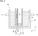
- FIG. 4 is a cross-sectional view showing another example of the purification device according to the first embodiment of the present invention.
- FIG. 5 is cross-sectional views showing examples of a purification unit according to a second embodiment of the present invention.
- FIG. 6 is cross-sectional views showing examples of a purification unit according to a third embodiment of the present invention.
- FIG. 7 is cross-sectional views showing examples of a purification unit according to a fourth embodiment of the present invention.
- FIG. 8 is cross-sectional views showing examples of a purification unit according to a fifth embodiment of the present invention.
- FIG. 9 is a cross-sectional view showing an example of a purification unit according to a sixth embodiment of the present invention.
- a purification device 100 includes a purification unit 1 as shown in FIG. 1 and FIG. 2 .
- the purification unit 1 includes a purification structure 40 composed of a positive electrode 10 that is a first electric conductor, a negative electrode 20 that is a second electric conductor, and an ion transfer layer 30 that is a third electric conductor 30 .
- the positive electrode 10 is disposed so as to contact one surface 30 a of the ion transfer layer 30
- the negative electrode 20 is disposed so as to contact a surface 30 b of the ion transfer layer 30 , which is opposite with the surface 30 a .
- the gas diffusion layer 12 of the positive electrode 10 is brought into contact with the ion transfer layer 30 , and a water-repellent layer 11 is exposed to a gas phase 50 .
- the cassette substrate 60 is a U-shaped frame member that goes along an outer peripheral portion of the surface 10 a in the positive electrodes 10 .
- An upper portion of the cassette substrate 60 is open. That is, the cassette substrate 60 is a frame member in which bottom surfaces of two first columnar members 61 are coupled to each other by a second columnar member 62 .
- a side surface 63 of the cassette substrate 60 is joined to the outer peripheral portion of the surface 10 a of the positive electrode 10
- a side surface 64 opposite with the side surface 63 is joined to an outer peripheral portion of a surface 70 a of a plate member 70 .
- the purification unit 1 composed by laminating the purification structure 40 , the cassette substrate 60 and the plate member 70 on one another is disposed inside a treatment tank 80 so that the gas phase 50 is formed.
- Wastewater 90 that is a treatment target is held inside the treatment tank 80 , and the positive electrode 10 , the negative electrode 20 and the ion transfer layer 30 are immersed in the wastewater 90 .
- the positive electrode 10 includes a water-repellent layer 11 having water repellency
- the plate member 70 is composed of a flat plate material that does not allow permeation of the wastewater 90 . Therefore, the wastewater 90 held inside the treatment tank 80 and the inside of the cassette substrate 60 are separated from each other, and the gas phase 50 is formed in an inner space formed of the purification structure 40 , the cassette substrate 60 and the plate member 70 . Then, the purification device 100 is configured so that this gas phase 50 is open to the outside air, or so that air is supplied from the outside to this gas phase 50 , for example, by a pump.
- the positive electrode 10 that is the first electric conductor is composed of a gas diffusion electrode including the water-repellent layer 11 and the gas diffusion layer 12 stacked on the water-repellent layer 11 to contact the same.
- a gas diffusion electrode including the water-repellent layer 11 and the gas diffusion layer 12 stacked on the water-repellent layer 11 to contact the same.
- Such a thin plate-shaped gas diffusion electrode as described above is used, whereby it becomes possible to easily supply a catalyst in the positive electrode 10 with oxygen in the gas phase 50 .
- the water-repellent layer 11 in the positive electrode 10 is a layer having both water repellency and oxygen permeability.
- the water-repellent layer 11 is configured so as, while satisfactorily separating the gas phase 50 and a liquid phase in an electrochemical system in the purification unit 1 from each other, to allow movement of oxygen, which shifts from the gas phase 50 to the liquid phase. That is, the water-repellent layer 11 can suppress the wastewater 90 from moving to the gas phase 50 while allowing the permeation of the oxygen in the gas phase 50 and moving the oxygen to the gas diffusion layer 12 . Note that such “separation” as used herein refers to physical blocking.
- the water-repellent layer 11 is in contact with the gas phase 50 having gas including oxygen, and diffuses the oxygen in the gas phase 50 . Then, in the configuration shown in FIG. 2 , the water-repellent layer 11 supplies oxygen to the gas diffusion layer 12 substantially uniformly. Therefore, it is preferable that the water-repellent layer 11 be a porous body so that the oxygen can be diffused. Note that, since the water-repellent layer 11 has water repellency, a decrease of oxygen diffusibility can be prevented, which may result from the fact that pores of the porous body are closed due to dew condensation and the like.
- the wastewater 90 is difficult to soak in an inside of the water-repellent layer 11 , it becomes possible to efficiently flow oxygen from the surface of the water-repellent layer 11 , which contacts the gas phase 50 , to the surface facing the gas diffusion layer 12 .
- the water-repellent layer 11 be formed of a woven fabric or a nonwoven fabric into a sheet shape.
- a material that composes the water-repellent layer 11 is not particularly limited as long as having water repellency and being capable of diffusing the oxygen in the gas phase 50 .
- the material that composes the water-repellent layer 11 for example, there can be used at least one selected from the group consisting of polyethylene, polypropylene, polybutadiene, nylon, polytetrafluoroethylene (PTFE), ethylcellulose, poly-4-methylpentene-1, butyl rubber, and polydimethylsiloxane (PDMS).
- the water-repellent layer 11 has a plurality of through holes in a lamination direction X of the water-repellent layer 11 and the gas diffusion layer 12 .
- the water-repellent layer 11 may be subjected to water-repellent treatment using a water-repellent agent as necessary.
- a water-repellent agent such as polytetrafluoroethylene may be adhered to the porous body that composes the water-repellent layer 11 , and may enhance the water repellency thereof.
- the gas diffusion layer 12 in the positive electrode 10 include a porous electroconductive material and a catalyst supported on this electroconductive material.
- the gas diffusion layer 12 may be composed of a porous catalyst having electro-conductivity.
- Such providing of such a gas diffusion layer 12 as described above in the positive electrode 10 makes it possible to conduct electrons, which are generated by a local cell reaction to be described later, between the negative electrode 20 and the catalyst. That is, as described later, the catalyst is supported on the gas diffusion layer 12 , and further, the catalyst is an oxygen reduction catalyst. Then, the electrons move from the negative electrode 20 through the gas diffusion layer 12 to the catalyst, whereby the catalyst makes it possible to advance an oxygen reduction reaction by oxygen, hydrogen ions and electrons.
- the gas diffusion layer 12 be a porous body that has a large number of oxygen-permeable pores from the surface facing the water-repellent layer 11 to the surface opposite therewith.
- a shape of the gas diffusion layer 12 be three-dimensionally mesh-like. Such a three-dimensional mesh shape makes it possible to impart high oxygen permeability and electro-conductivity to the gas diffusion layer 12 .
- the water-repellent layer 11 be joined to the gas diffusion layer 12 via an adhesive. In this way, the diffused oxygen is directly supplied to the gas diffusion layer 12 , and the oxygen reduction reaction can be carried out efficiently. From a viewpoint of ensuring adhesive properties between the water-repellent layer 11 and the gas diffusion layer 12 , it is preferable that the adhesive be provided on at least a part between the water-repellent layer 11 and the gas diffusion layer 12 .
- the adhesive be provided over the entire surface between the water-repellent layer 11 and the gas diffusion layer 12 .
- an adhesive having oxygen permeability is preferable, and a resin can be used, which includes at least one selected from the group consisting of polymethyl methacrylate, methacrylic acid-styrene copolymer, styrene-butadiene rubber, butyl rubber, nitrile rubber, chloroprene rubber and silicone.
- the gas diffusion layer 12 of the positive electrode 10 can be configured to include a porous electroconductive material and a catalyst supported on the electroconductive material.
- the electroconductive material in the gas diffusion layer 12 can be composed of at least one material selected from the group consisting of graphite foil, carbon paper, carbon cloth and stainless steel (SUS). More specifically, the electroconductive material in the gas diffusion layer 12 can be composed, for example, of at least one material selected from the group consisting of a carbon-based substance, an electrically conductive polymer, a semiconductor and metal.
- the carbon-based substance refers to a substance containing carbon as a constituent.
- Examples of the carbon-based substance include, for example: carbon powder such as graphite, activated carbon, carbon black, Vulcan (registered trademark) XC-72R, acetylene black, furnace black, and Denka Black; carbon fiber such as graphite felt, carbon wool and carbon woven fabric; carbon plate; carbon paper; carbon disc; carbon cloth; carbon foil; and carbon-based material molded by compressing carbon particles.
- the examples of the carbon-based substance also include microstructured substances such as carbon nanotubes, carbon nanohorns and carbon nanoclusters.
- the electrically conductive polymer is a generic name of high molecular compounds having electro-conductivity.
- Examples of the electrically conductive polymer include: polymers of single monomers or two or more monomers, which are composed of, as elements, aniline, aminophenol, diaminophenol, pyrrole, thiophene, paraphenylene, fluorene, furan, acetylene, or derivatives thereof.
- Specific examples of the electrically conductive polymer include polyaniline, polyaminophenol, polydiaminophenol, polypyrrole, polythiophene, polyparaphenylene, polyfluorene, polyfuran, polyacetylene and the like.
- the metal electroconductive material includes metal materials having mesh, foam and other shapes, and for example, a stainless steel mesh can be used. Note that, considering availability, cost, corrosion resistance, durability and the like, it is preferable that the electroconductive material be the carbon-based substance.
- a shape of the electroconductive material be a powdery shape or a fibrous shape.
- the electroconductive material may be supported on a support.
- the support means a member that itself has rigidity and can impart a constant shape to the gas diffusion electrode.
- the support may be an insulator or an electric conductor.
- examples of the support include glass pieces, plastics, synthetic rubbers, ceramics, paper subjected to waterproof or water-repellent treatment, plant pieces such as wood pieces, animal pieces such as bone pieces and shells, and the like.
- Examples of a support having a porous structure include porous ceramics, porous plastics, sponge and the like.
- the support When the support is an electric conductor, examples of the support include carbon-based substances such as carbon paper, carbon fiber and carbon rod, metals, electrically conductive polymers, and the like.
- the support When the support is an electric conductor, such an electroconductive material that supports the carbon-based material is disposed on a surface of the support, whereby the support can also function as a current collector.
- the catalyst in the gas diffusion layer 12 there can be used a platinum-based catalyst, a carbon-based catalyst using iron or cobalt, a transition metal oxide-based catalyst including partially oxidized tantalum carbon nitride (TaCNO) and zirconium carbon nitride (ZrCNO), a carbide-based catalyst using tungsten or molybdenum, activated carbon, and the like.
- a platinum-based catalyst a carbon-based catalyst using iron or cobalt
- a transition metal oxide-based catalyst including partially oxidized tantalum carbon nitride (TaCNO) and zirconium carbon nitride (ZrCNO)
- a carbide-based catalyst using tungsten or molybdenum activated carbon, and the like.
- the catalyst in the gas diffusion layer 12 be a carbon-based material doped with metal atoms.
- the metal atoms are not particularly limited; however, it is preferable that the metal atoms be atoms of at least one metal selected from the group consisting of titanium, vanadium, chromium, manganese, iron, cobalt, nickel, copper, zirconium, niobium, molybdenum, ruthenium, rhodium, palladium, silver, hafnium, tantalum, tungsten, rhenium, osmium, iridium, platinum and gold.
- the carbon-based material exerts excellent performance particularly as a catalyst for promoting the oxygen reduction reaction.
- An amount of the metal atoms contained in the carbon-based material may be appropriately set so that the carbon-based material has excellent catalytic performance.
- the carbon-based material be further doped with atoms of at least one nonmetal selected from nitrogen, boron, sulfur and phosphorus.
- An amount of such nonmetal atoms doped into the carbon-based material may also be appropriately set so that the carbon-based material has such excellent catalytic performance.
- the carbon-based material is obtained, for example, in such a manner that a carbon-source raw material such as graphite and amorphous carbon is used as a base, and that this carbon-source raw material is doped with the metal atoms and the atoms of the at least one nonmetal selected from nitrogen, boron, sulfur and phosphorus.
- a carbon-source raw material such as graphite and amorphous carbon is used as a base, and that this carbon-source raw material is doped with the metal atoms and the atoms of the at least one nonmetal selected from nitrogen, boron, sulfur and phosphorus.
- the metal atoms and the nonmetal atoms which are doped into the carbon-based material, are appropriately selected.
- the nonmetal atoms include nitrogen, and that the metal atoms include iron.
- the carbon-based material can have particularly excellent catalytic activity. Note that the nonmetal atoms may be only nitrogen and the metal atoms may be only iron.
- the nonmetal atoms may include nitrogen, and the metal atoms may include at least either one of cobalt and manganese.
- the carbon-based material can have particularly excellent catalytic activity.
- the nonmetal atoms may be only nitrogen.
- the metal atoms may be only cobalt, only manganese, or only cobalt and manganese.
- the shape of the carbon-based material is not particularly limited.
- the carbon-based material may have a particulate shape or a sheet-like shape.
- Dimensions of the carbon-based material having the sheet-like shape are not particularly limited; however, for example, the carbon-based material may have minute dimensions.
- the carbon-based material having the sheet-like shape may be porous. It is preferable that the porous carbon-based material having the sheet-like shape have, for example, a woven fabric shape, a nonwoven fabric shape, and the like.
- Such a carbon-based material as described above can constitute the gas diffusion layer 12 without the need for the electroconductive material.
- the carbon-based material composed as the catalyst in the gas diffusion layer 12 can be prepared as follows. First, a mixture is prepared, which contains a nonmetal compound including at least one nonmetal selected from the group consisting of nitrogen, boron, sulfur and phosphorus, a metal compound, and the carbon-source raw material. Then, this mixture is heated at a temperature of 800° C. or more to 1000° C. or less for 45 seconds or more and less than 600 seconds. In this way, the carbon-based material composed as the catalyst can be obtained.
- the metal compound is not particularly limited as long as the metal compound is a compound including metal atoms capable of coordinate bond with the nonmetal atoms to be doped into the carbon-source raw material.
- the metal compound for example, there can be used at least one selected from the group consisting of: inorganic metal salt such as metal chloride, nitrate, sulfate, bromide, iodide and fluoride; organic metal salt such as metal acetate; a hydrate of the inorganic metal salt; and a hydrate of the organic metal salt.
- the metal compound when the graphite is doped with iron, it is preferable that the metal compound contain iron chloride (III). When the graphite is doped with cobalt, it is preferable that the metal compound contain cobalt chloride. Moreover, when the carbon-source raw material is doped with manganese, it is preferable that the metal compound contain manganese acetate. It is preferable that an amount of use of the metal compound be determined so that a ratio of the metal atoms in the metal compound to the carbon-source raw material can stay within a range of 5 to 30% by mass, and it is more preferable that the amount of use of the metal compound be determined so that this ratio can stay within a range of 5 to 20% by mass.
- the nonmetal compound be a compound of at least one nonmetal selected from the group consisting of nitrogen, boron, sulfur and phosphorus.
- the nonmetal compound for example, there can be used at least one compound selected from the group consisting of pentaethylenehexamine, ethylenediamine, tetraethylenepentamine, triethylenetetramine, ethylenediamine, octylboronic acid, 1,2-bis(diethylphosphinoethane), triphenyl phosphite, and benzyl disulfide.
- An amount of use of the nonmetal compound is appropriately set according to a doping amount of the nonmetal atoms into the carbon-source raw material.
- the amount of use of the nonmetal compound be determined so that a molar ratio of the metal atoms in the metal compound and the nonmetal atoms in the nonmetal compound can stay within a range of 1:1 to 1:2, and it is more preferable that the amount of use of the nonmetal compound be determined so that this molar ratio can stay within a range of 1:1.5 to 1:1.8.
- the mixture containing the nonmetal compound, the metal compound and the carbon-source raw material in the case of preparing the carbon-based material composed as the catalyst can be obtained, for example, as follows. First, the carbon-source raw material, the metal compound, and the nonmetal compound are mixed with one another, and as necessary, a solvent such as ethanol is added to an obtained mixture, and a total amount of the mixture is adjusted. These are further dispersed by an ultrasonic dispersion method. Subsequently, after these are heated at an appropriate temperature (for example, 60° C.), the mixture is dried to remove the solvent. In this way, such a mixture containing the nonmetal compound, the metal compound and the carbon-source raw material is obtained.
- a solvent such as ethanol
- the obtained mixture is heated, for example, in a reducing atmosphere or an inert gas atmosphere.
- the nonmetal atoms are doped into the carbon-source raw material, and the metal atoms are also doped thereinto by the coordinate bond between the nonmetal atoms and the metal atoms.
- a heating temperature be within a range of 800° C. or more to 1000° C. or less, and it is preferable that a heating time be within a range of 45 seconds or more to less than 600 seconds. Since the heating time is short, the carbon-based material is efficiently produced, and the catalytic activity of the carbon-based material is further increased.
- a heating rate of the mixture at the start of heating in the heating treatment is 50° C./s or more. Such rapid heating further enhances the catalytic activity of the carbon-based material.
- the carbon-based material may be further acid-washed.
- the carbon-based material may be dispersed in pure water for 30 minutes by a homogenizer, and thereafter, the carbon-based material may be placed in 2 M sulfuric acid and stirred at 80° C. for 3 hours. In this case, elution of the metal component from the carbon-based material is reduced.
- the catalyst may be bound to the electroconductive material using a binding agent. That is, the catalyst may be supported on surfaces and pore insides of the electroconductive material using the binding agent. In this way, the oxygen reduction properties of the catalyst can be prevented from being degraded due to desorption of the catalyst from the electroconductive material.
- the binding agent for example, it is preferable to use at least one selected from the group consisting of polytetrafluoroethylene, polyvinylidene fluoride (PVDF), and ethylene-propylene-diene copolymer (EPDM).
- PVDF polyvinylidene fluoride
- EPDM ethylene-propylene-diene copolymer
- Nafion registered trademark
- the negative electrode 20 that is the second electric conductor according to this embodiment has functions to support microorganisms to be described later, and further, to generate hydrogen ions and electrons from at least either of the organic matter and a nitrogen-containing compound in the wastewater 90 by a catalytic action of the microorganisms. Therefore, the negative electrode 20 of this embodiment is not particularly limited as long as the negative electrode 20 has a configuration of generating such functions.
- the negative electrode 20 in this embodiment has a structure in which microorganisms are supported on an electrically conductive sheet having electro-conductivity.
- the electrically conductive sheet there can be used at least one selected from the group consisting of a porous electrically conductive sheet, a woven fabric electrically conductive sheet, and a nonwoven fabric electrically conductive sheet.
- the electrically conductive sheet may be a laminated body formed by laminating a plurality of sheets on one another.
- Such a sheet having a plurality of pores is used as the electrically conductive sheet of the negative electrode 20 , whereby it becomes easy for hydrogen ions generated by a local cell reaction to be described later to move in a direction of the positive electrode 10 , thus making it possible to increase the rate of the oxygen reduction reaction.
- the electrically conductive sheet of the negative electrode 20 have a space (air gap) continuous in the lamination direction X, that is, in a thickness direction of the electrically conductive sheet.
- At least one selected from the group consisting of graphite foil, graphite brush and carbon felt can be used.
- the graphite brush is a product in which a bundle of carbon fibers is attached with a handle, and the graphite brush has electro-conductivity as a whole.
- the electrically conductive sheet in the negative electrode 20 may be a metal plate having a plurality of through holes in the thickness direction. Therefore, as a material that composes the electrically conductive sheet of the negative electrode 20 , for example, electrically conductive metal such as aluminum, copper, stainless steel, nickel and titanium can also be used.
- the microorganisms supported on the negative electrode 20 are not particularly limited as long as being microorganisms which degrade organic matter or a compound containing nitrogen in the wastewater 90 ; however, it is preferable to use anaerobic microorganisms which do not require oxygen for growth thereof.
- the anaerobic microorganisms do not require air for oxidatively degrading the organic matter in the wastewater 90 . Therefore, electric power required to send air can be reduced to a large extent. Moreover, since free energy acquired by the microorganisms is small, it becomes possible to reduce an amount of generated sludge.
- the microorganisms held in the negative electrode 20 are anaerobic microorganisms, and for example, preferably are electricity-producing bacteria having an extracellular electron transfer mechanism.
- the anaerobic microorganisms include Geobacter bacteria, Shewanella bacteria, Aeromonas bacteria, Geothrix bacteria, and Saccharomyces bacteria.
- the negative electrode 20 may hold the anaerobic microorganisms in such a manner that a biofilm including the anaerobic microorganisms is laminated and fixed to the negative electrode 20 itself.
- the anaerobic microorganisms may be held on a surface 20 b of the negative electrode 20 , which is opposite with the contact surface 20 a that contacts the ion transfer layer 30 .
- biofilm generally refers to a three-dimensional structure including a microbial population and an extracellular polymeric substance (EPS) produced by the microbial population.
- EPS extracellular polymeric substance
- the anaerobic microorganisms may be held on the negative electrode 20 without using the biofilm.
- the anaerobic microorganisms may be held not only on the surface of the negative electrode 20 but also in the inside thereof.
- the anaerobic microorganisms be supported on at least either one of the surface and inside of the negative electrode 20 .
- the fact that these microorganisms are contained in the wastewater 90 is sufficient to exert the effects of this embodiment. Therefore, in the purification device 100 , it is preferable that at least either one of the negative electrode 20 and the wastewater 90 hold the anaerobic microorganisms.
- the purification unit 1 of this embodiment further includes the ion transfer layer 30 that is provided between the positive electrode 10 and the negative electrode 20 , has hydrogen ion permeability and is the third electric conductor. Then, as shown in FIG. 1 and FIG. 2 , the negative electrode 20 is separated from the positive electrode 10 via the ion transfer layer 30 . Moreover, at least a part of the positive electrode 10 is electrically connected to the one surface 30 a of the ion transfer layer 30 , and at least a part of the negative electrode 20 is electrically connected to the other surface 30 b of the ion transfer layer 30 .
- the ion transfer layer 30 has a function to allow the permeation of the hydrogen ions generated at the negative electrode 20 , and to move the generated hydrogen ions to the positive electrode 10 . Therefore, the hydrogen ions generated at the negative electrode 20 move through the inside of the ion transfer layer 30 , react with oxygen at the positive electrode 10 , and generate water.
- a configuration of the ion transfer layer 30 is not particularly limited as long as the configuration enables the hydrogen ions to conduct without greatly inhibiting the diffusion thereof.
- the ion transfer layer 30 a porous membrane having pores capable of allowing the permeation of the hydrogen ions may be used. That is, the ion transfer layer 30 may be a sheet having a space (air gap) for allowing the hydrogen ions to move between the positive electrode 10 and the negative electrode 20 . Therefore, it is preferable that the ion transfer layer 30 have at least one selected from the group consisting of a porous sheet, a woven fabric sheet and a nonwoven fabric sheet. Note that a pore size of the ion transfer layer 30 is not particularly limited as long as the hydrogen ions can move between the positive electrode 10 and the negative electrode 20 .
- the ion transfer layer 30 be composed of an electric conductor. That is, in the purification unit 1 , the gas diffusion layer 12 of the positive electrode 10 is disposed so as to contact the one surface 30 a of the ion transfer layer 30 , and the negative electrode 20 is disposed so as to contact the surface 30 b of the ion transfer layer 30 , which is opposite with the surface 30 a . Therefore, when the ion transfer layer 30 has electro-conductivity, the positive electrode 10 and the negative electrode 20 are short-circuited. As a result, it becomes possible for the electrons generated at the negative electrode 20 to move to the positive electrode 10 , and possible to cause the oxygen reduction reaction at the positive electrode 10 .
- the electrically conductive ion transfer layer 30 is not particularly limited as long as the ion transfer layer 30 has therein a space that enables the hydrogen ions to move, and is electrically connected to the positive electrode 10 and the negative electrode 20 .
- the ion transfer layer 30 may be extended continuously from the negative electrode 20 toward the positive electrode 10 .
- the ion transfer layer 30 may be composed of a plurality of electrically conductive portions electrically connected to one another, and for example, may have a configuration in which the plurality of electrically conductive layers is laminated on and electrically connected to one another.
- At least a part of the material that composes the ion transfer layer 30 may be extended continuously from the negative electrode 20 toward the positive electrode 10 , and further, may be extended so as to cross the space. That is, at least a part of the material that composes the ion transfer layer 30 may be extended in a direction perpendicular to the lamination direction X of the positive electrode 10 , the negative electrode 20 and the ion transfer layer 30 .
- the material of the ion transfer layer 30 is not particularly limited as long as the material can ensure the electro-conductivity.
- at least one selected from the group consisting of electrically conductive metal, carbon material and electrically conductive polymer material can be used.
- electrically conductive metal for example, at least one selected from the group consisting of aluminum, copper, stainless steel, nickel and titanium can be used.
- carbon material for example, at least one selected from the group consisting of carbon paper, carbon felt, carbon cloth and graphite foil can be used.
- the electrically conductive polymer material at least one selected from the group consisting of polyacetylene, polythiophene, polyaniline, poly(p-phenylenevinylene), polypyrrole and poly (p-phenylene sulfide) can be used.
- the ion transfer layer 30 includes at least either one of an electrically conductive sheet having a woven fabric form and an electrically conductive sheet having a nonwoven fabric form.
- the electrically conductive sheet having a woven fabric form and the electrically conductive sheet having a nonwoven fabric form have a large number of pores, and accordingly, can facilitate the hydrogen ions to move.
- the ion transfer layer 30 may be a metal plate having a plurality of through holes from the negative electrode 20 across the positive electrode 10 .
- the ion transfer layer 30 include the electrically conductive sheet having a nonwoven fabric form, and it is particularly preferable that the ion transfer layer 30 be composed of the electrically conductive sheet having a nonwoven fabric form. It is easy to change a thickness and porosity of the nonwoven fabric, and accordingly, it becomes possible to easily improve the permeability of the hydrogen ions.
- the negative electrode 20 is supplied with the wastewater 90 containing at least either one of the organic matter and the nitrogen-containing compound, and the positive electrode 10 is supplied with air or oxygen. At this time, air and oxygen are continuously supplied to the gas phase 50 .
- the positive electrode 10 shown in FIG. 1 and FIG. 2 air permeates the water-repellent layer 11 and is diffused by the gas diffusion layer 12 .
- hydrogen ions and electrons are generated from at least either one of the organic matter and the nitrogen-containing compound in the wastewater 90 by the catalytic action of the microorganisms.
- the generated hydrogen ions pass through an inner space of the ion transfer layer 30 , the inner space having the wastewater 90 be present therein, and move to the positive electrode 10 .
- the generated electrons move to the ion transfer layer 30 through the electrically conductive sheet of the negative electrode 20 , and further, move to the gas diffusion layer 12 of the positive electrode 10 .
- the hydrogen ions and the electrons are combined with oxygen by an action of the catalyst supported on the gas diffusion layer 12 , and are consumed as water.
- the above-mentioned local cell reaction (half-cell reaction) is represented by the following formula.
- the local cell reaction is represented by the following formula.
- the catalytic action of the microorganisms in the negative electrode 20 makes it possible to degrade the organic matter and the nitrogen-containing compound in the wastewater 90 , and to purify the wastewater 90 .
- hydroxide ions are sometimes generated by the reduction reaction of oxygen in the positive electrode 10 . Therefore, in some cases, the generated hydroxide ions move through the inside of the ion transfer layer 30 , and are combined with the hydrogen ions generated in the negative electrode 20 , whereby water is generated.
- the ion transfer layer 30 that is the third electric conductor have higher electrical resistivity than the positive electrode 10 that is the first electric conductor and the negative electrode 20 that is the second electric conductor have.
- the ion transfer layer 30 have higher electrical resistivity than the positive electrode 10 and the negative electrode 20 while having electro-conductivity, whereby the positive electrode 10 and the negative electrode 20 can be controlled to appropriate potentials, and the potential difference between the positive electrode 10 and the negative electrode 20 can be ensured.
- metabolism of the microorganisms, which follows electronic conduction is promoted, and accordingly, it becomes possible to increase degradation efficiency of the organic matter and the nitrogen-containing compound in the treatment target.
- the purification unit 1 can adopt a simpler configuration, and the purification device 100 can be downsized.
- the electrical resistivity of each of the first electric conductor and the second electric conductor refers to electrical resistivity of a surface thereof in contact with the third electric conductor. That is, in this embodiment, the electrical resistivity of the first electric conductor is electrical resistivity of the surface 10 b of the positive electrode 10 . Moreover, the electrical resistivity of the second electric conductor is electrical resistivity of the surface 20 a of the negative electrode 20 . The electrical resistivity of the surface of each of the first electric conductor and the second electric conductor, the surface being in contact with the third electric conductor, can be measured by the four-point probe method.
- the electrical resistivity of the third electric conductor is electrical resistivity of a surface perpendicular to the surfaces of the third electric conductor, which are in contact with the first electric conductor and the second electric conductor. That is, in this embodiment, the electrical resistivity of the ion transfer layer 30 that is the third electric conductor is the lowest value among values measured on the upper surface 30 c and the lower surface 30 d , which are shown in FIG. 2 , and on the right side surface 30 e and the left side surface 30 f , which are shown in FIG. 3 . Moreover, the electrical resistivity of the third electric conductor is a value measured by the four-point probe method along a lamination direction of the first electric conductor, the second electric conductor and the third electric conductor. That is, in this embodiment, the electrical resistivity of the ion transfer layer 30 that is the third electric conductor is a value measured by the four-point probe method along the X-axis direction that is the lamination direction.
- the purification unit 1 includes the first electric conductor, the second electric conductor different from the first electric conductor, and the third electric conductor different from the first electric conductor and the second electric conductor. Then, at least a part of the first electric conductor is electrically connected to one surface of the third electric conductor, and at least a part of the second electric conductor is electrically connected to the other surface of the third electric conductor. Moreover, at least a part of the first electric conductor contacts a gas phase 50 including oxygen, and at least a part of the second electric conductor contacts a treatment target.
- the purification device 100 includes: the above-mentioned purification unit 1 ; and the treatment tank 80 for holding therein the purification unit 1 and the wastewater 90 to be purified by the purification unit 1 . Then, the purification unit 1 is installed so that at least a part of the first electric conductor contacts the gas phase 50 , and that at least a part of the second electric conductor contacts the wastewater 90 .
- the purification device 100 of this embodiment can oxidatively degrade the component (organic matter or nitrogen-containing compound) contained in the wastewater 90 in an efficient manner. Specifically, the organic matter and/or the nitrogen-containing compound, which is contained in the wastewater 90 , is degraded and removed by the metabolism of the anaerobic microorganisms, that is, by growth of the microorganisms. Then, since this oxidative degradation treatment is performed under an anaerobic condition, conversion efficiency of the organic matter into new microbial cells can be kept lower than in the case where the oxidative degradation treatment is performed under an aerobic condition.
- the growth of the microorganisms that is, the amount of generated sludge can be reduced more than in the case of using the activated sludge process.
- the generation of methane gas can be suppressed in the oxidative degradation treatment in this embodiment since a metabolite is carbon dioxide gas for example.
- the third electric conductor have higher electrical resistivity than the first electric conductor and the second electric conductor have. That is, it is preferable that the first electric conductor and the second electric conductor not be in direct contact with each other but be electrically connected with each other via the third electric conductor having relatively high electrical resistivity. In this way, the potential difference between the first electric conductor and the second electric conductor is ensured, thus making it easy to transfer electrons from the second electric conductor to the first electric conductor. As a result, the metabolism of the microorganisms, which follows the electronic conduction, is promoted, and accordingly, it becomes possible to increase the degradation efficiency of the organic matter and the nitrogen-containing compound in the treatment target.
- the first electric conductor include the oxygen reduction catalyst. In this way, in the first electric conductor, the oxygen reduction reaction between the oxygen in the gas phase 50 and the hydrogen ions and the electrons, which are generated in the second electric conductor, is promoted, and accordingly, it becomes possible to purify the treatment target more efficiently.
- the anaerobic microorganisms be supported on at least either one of the surface and inside of the second electric conductor.
- the anaerobic microorganisms are used, whereby the growth of the microorganisms, that is, the amount of generated sludge can be reduced, and further, it also becomes possible to suppress the generation of the methane gas.
- the ion transfer layer 30 that is the third electric conductor is in contact with the entire surface 10 b of the positive electrode 10 that is the first electric conductor and with the entire surface 20 a of the negative electrode 20 that is the second electric conductor.
- the purification unit 1 is not limited to such a mode, and at least a part of the positive electrode 10 just needs to be electrically connected to the surface 30 a of the ion transfer layer 30 , and at least a part of the negative electrode 20 just needs to be electrically connected to the surface 30 b of the ion transfer layer 30 . Therefore, as shown in FIG.
- such a mode may be adopted in which the ion transfer layer 30 contacts a part of the surface 10 b of the positive electrode 10 and the surface 20 a of the negative electrode 20 . Moreover, in this case, the whole of the ion transfer layer 30 may be immersed in the wastewater 90 .
- the positive electrode 10 that is the first electric conductor and the negative electrode 20 that is the second electric conductor are electrically connected to each other by the ion transfer layer 30 that is the third electric conductor. Then, in FIG. 4 , the positive electrode 10 and the negative electrode 20 are electrically connected to each other by the single ion transfer layer 30 ; however, this embodiment is not limited to such a mode. That is, the positive electrode 10 and the negative electrode 20 may be connected to each other using a plurality of the ion transfer layers 30 .
- the wastewater 90 makes it possible to move the hydrogen ions from the second electric conductor to the first electric conductor, and accordingly, the third electric conductor itself does not have to have the ion conductivity.
- the purification unit 1 when the microorganisms contact the positive electrode 10 that is the first electric conductor, possibly, a condensate caused by a secretory component of the microorganisms may be fixedly attached to the positive electrode 10 , oxygen may be consumed excessively by the microorganisms, and a local pH gradient may be formed, resulting in a decrease of a reaction amount following the electron transfer. Therefore, it is preferable that such adhesion of the microorganisms to the positive electrode 10 be inhibited as much as possible.
- a method for inhibiting the adhesion of the microorganisms to the positive electrode 10 includes: a method using the ion transfer layer 30 having pores with a pore size that does not allow physical passage of the microorganisms; or a method using chemical/biological actions of the ion transfer layer 30 .
- the method using the chemical/biological actions includes a method of fixing a disinfectant for sterilizing the microorganisms to the ion transfer layer 30 .
- the disinfectant for example, tetracycline and a compound that emits silver or copper ions having disinfectant properties can be used.
- the method using the chemical/biological actions includes a method of providing the ion transfer layer 30 itself with local pH going out of a range where the microorganisms are capable of growing.
- the treatment tank 80 holds the wastewater 90 in the inside thereof, and may have a configuration through which the wastewater 90 is circulated.
- the treatment tank 80 may be provided with a wastewater supply port 81 for supplying the wastewater 90 to the treatment tank 80 and a wastewater discharge port 82 for discharging the treated wastewater 90 from the treatment tank 80 . Then, it is preferable that the wastewater 90 be continuously supplied through the wastewater supply port 81 and the wastewater discharge port 82 .
- the negative electrode 20 that is the second electric conductor according to this embodiment may be modified by electron transfer mediator molecules.
- the wastewater 90 in the treatment tank 80 may contain the electron transfer mediator molecules. In this way, the electron transfer from the anaerobic microorganisms to the negative electrode 20 is promoted, and more efficient liquid treatment can be achieved.
- the mediator molecules act as the final electron acceptors for metabolism, and deliver the received electrons to the negative electrode 20 .
- the electron transfer mediator molecules as described above are not particularly limited.
- the electron transfer mediator molecules as described above for example, there can be used at least one selected from the group consisting of neutral red, anthraquinone-2,6-disulfonic acid (AQDS), thionine, potassium ferricyanide, and methyl viologen.
- AQDS anthraquinone-2,6-disulfonic acid
- thionine thionine
- potassium ferricyanide potassium ferricyanide
- methyl viologen there can be used at least one selected from the group consisting of neutral red, anthraquinone-2,6-disulfonic acid (AQDS), thionine, potassium ferricyanide, and methyl viologen.
- the purification unit includes a first electric conductor 10 A, a second electric conductor 20 A different from the first electric conductor 10 A, and a third electric conductor 30 A different from the first electric conductor 10 A and the second electric conductor 20 A. Then, at least a part of the first electric conductor 10 A is electrically connected to one surface 30 a of the third electric conductor 30 A, and at least a part of the second electric conductor 20 A is electrically connected to the other surface 30 b of the third electric conductor 30 A.
- the first electric conductor 10 A is electrically connected to the one surface 30 a of the third electric conductor 30 A by contacting the same one surface 30 a
- the second electric conductor 20 A is electrically connected to the other surface 30 b of the third electric conductor 30 A by contacting the same other surface 30 b.
- the first electric conductor 10 A is exposed from a water surface 90 a of the wastewater 90 , and is brought into direct contact with air that is the gas phase including oxygen. Therefore, this purification unit does not have to include the cassette substrate 60 and the plate member 70 for forming the gas phase 50 , which are used in the first embodiment. Moreover, the first electric conductor 10 A does not have to include the water-repellent layer 11 in the positive electrode 10 of the first embodiment. Therefore, the first electric conductor 10 A can adopt the same configuration as that of the gas diffusion layer 12 of the positive electrode 10 in the first embodiment, and the second electric conductor 20 A can adopt the same configuration as that of the negative electrode 20 in the first embodiment. Furthermore, the third electric conductor 30 A can adopt the same configuration as that of the ion transfer layer 30 in the first embodiment.
- the purification unit is installed so that at least a part of the first electric conductor 10 A contacts the gas phase 50 including oxygen, and that at least a part of the second electric conductor 20 A contacts the wastewater 90 that is the treatment target.
- the second electric conductor 20 A and the third electric conductor 30 A are in contact with the wastewater 90 , and accordingly, the wastewater 90 is present therein. Therefore, the second electric conductor 20 A and the third electric conductor 30 A enable the hydrogen ions to move by the wastewater 90 therein.
- the first electric conductor 10 A is also partially in contact with the wastewater 90 , and the wastewater 90 is present therein.
- the wastewater 90 can be raised by a capillary phenomenon, and can be held inside the first electric conductor 10 A. Therefore, the first electric conductor 10 A also enables the hydrogen ions to move by the wastewater 90 therein.
- the purification device of this embodiment can also function in a similar way to the first embodiment. Specifically, when the purification device is operated, the wastewater 90 containing at least either one of the organic matter and the nitrogen-containing compound is supplied to the second electric conductor 20 A, and air or oxygen is supplied to the first electric conductor 10 A. At this time, the first electric conductor 10 A is exposed to air, and accordingly, is supplied with air continuously.
- the hydrogen ions and the electrons are generated from at least either one of the organic matter and the nitrogen-containing compound in the wastewater 90 by the catalytic action of the microorganisms.
- the generated hydrogen ions pass through an inner space of the third electric conductor 30 A, and move to the first electric conductor 10 A.
- the generated electrons move to the third electric conductor 30 A through the second electric conductor 20 A, and further, move to the first electric conductor 10 A.
- the hydrogen ions and the electrons are combined with oxygen by an action of the catalyst supported on the first electric conductor 10 A, and are consumed as water.
- the purification device of this embodiment can also oxidatively degrade the organic matter and the nitrogen-containing compound, which are contained in the wastewater 90 in an efficient manner. Then, since this oxidative degradation treatment is performed under an anaerobic condition, the growth of the microorganisms, that is, the amount of generated sludge can be reduced more than in the case of using the activated sludge process. Moreover, the generation of methane gas can be suppressed in the oxidative degradation treatment in this embodiment since a metabolite is carbon dioxide gas for example.
- the purification unit for use in this embodiment the first electric conductor 10 A is exposed to air, and accordingly, the water-repellent layer 11 , the cassette substrate 60 and the plate member 70 for forming the gas phase 50 become unnecessary. Therefore, it becomes possible to simplify the structure of the purification unit.
- the purification unit according to this embodiment is not particularly limited as long as the purification unit is configured so that at least a part of the first electric conductor 10 A can be exposed from the water surface 90 a of the wastewater 90 , and that the second electric conductor 20 A can be immersed in the wastewater 90 .
- the purification unit can be configured as shown in FIGS. 5( a ) to 5( d ) .
- the first electric conductor 10 A is disposed substantially horizontally with respect to the water surface 90 a
- the second electric conductor 20 A is disposed substantially perpendicularly to the first electric conductor 10 A
- the third electric conductor 30 A is interposed between the first electric conductor 10 A and the second electric conductor 20 A.
- each of the second electric conductor 20 A and the third electric conductor 30 A is not limited to be single, and a plurality of the second electric conductors 20 A and a plurality of the third electric conductor 30 A may be connected to the first electric conductor 10 A that is single.
- the first electric conductor 10 A is disposed substantially horizontally to the water surface 90 a
- the second electric conductor 20 A is disposed substantially parallel to the first electric conductor 10 A.
- a plurality of the third electric conductors 30 A is interposed between the first electric conductor 10 A and the second electric conductor 20 A. Note that, in the purification unit 1 B in FIG. 5( b ) , the first electric conductor 10 A and the second electric conductor 20 A are close to each other, and an electronic conduction path reaching the first electric conductor 10 A from the second electric conductor 20 A through the third electric conductors 30 A is relatively short.
- electro-conductivity from the second electric conductor 20 A to the first electric conductor 10 A is high.
- a substrate having relatively high electrical resistance may be used for the first electric conductor 10 A and the second electric conductor 20 A, and even in that case, it becomes possible to purify the wastewater 90 efficiently.
- the first electric conductor 10 A is disposed substantially horizontally to the water surface 90 a , and the third electric conductor 30 A is interposed between the first electric conductor 10 A and the second electric conductor 20 A.
- the second electric conductor 20 A has a substantially T-shaped cross section.
- the first electric conductor 10 A is disposed substantially horizontally to the water surface 90 a
- the third electric conductor 30 A is interposed between the first electric conductor 10 A and the second electric conductor 20 A.
- the second electric conductor 20 A has a substantially H-shaped cross section.
- the anaerobic microorganisms be supported on the surface or inside of the second electric conductor 20 A, it is preferable that a periphery of the second electric conductor 20 A be an anaerobic atmosphere. Therefore, it is preferable that the second electric conductor 20 A be disposed at a position apart from the water surface 90 a .
- the first electric conductor 10 A is disposed on the water surface 90 a of the wastewater 90 , and accordingly, it is preferable that the second electric conductor 20 A be disposed at a position apart from the first electric conductor 10 A.
- the wastewater 90 be held up to the upper surface 10 c of the first electric conductor 10 A in order to ensure conductivity of the hydrogen ions to the oxygen reduction catalyst.
- an ion conductive material inside the first electric conductor 10 A, it becomes possible to conduct the hydrogen ions up to the oxygen reduction catalyst even if the wastewater 90 is not held.
- ion conductive material for example, there can be used Nafion (registered trademark) containing a perfluorosulfonic acid group, Flemion (registered trademark) composed of perfluoro-type vinyl ether containing a carboxylic acid group.
- the purification unit according to this embodiment also has a configuration similar to that in the second embodiment.
- the purification unit includes a first electric conductor 10 B, a second electric conductor 20 B different from the first electric conductor 10 B, and a third electric conductor 30 B different from the first electric conductor 10 B and the second electric conductor 20 B. Then, at least a part of the first electric conductor 10 B is electrically connected to one surface 30 a of the third electric conductor 30 B, and at least a part of the second electric conductor 20 B is electrically connected to the other surface 30 b of the third electric conductor 30 B.
- the first electric conductor 10 B is electrically connected to the one surface 30 a of the third electric conductor 30 B by contacting the same one surface 30 a
- the second electric conductor 20 B is electrically connected to the other surface 30 b of the third electric conductor 30 B by contacting the same other surface 30 b .
- the first electric conductor 10 B and the second electric conductor 20 B are connected to each other in the vertical direction via the third electric conductor 30 B.
- the first electric conductor 10 B and the second electric conductor 20 B are connected to each other in the vertical direction via the third electric conductor 30 B. Then, the second electric conductor 20 B, the third electric conductor 30 B and a part of the first electric conductor 10 B are immersed in the wastewater 90 . Moreover, in order to increase a contact area with the gas phase 50 , the cassette substrate 60 and the plate member 70 are provided in the first electric conductor 10 B. Therefore, it is preferable that the first electric conductor 10 B adopt the same configuration as that of the positive electrode 10 including the water-repellent layer 11 and the gas diffusion layer 12 in the first embodiment. Moreover, the second electric conductor 20 B can adopt the same configuration as that of the negative electrode 20 in the first embodiment, and the third electric conductor 30 B can adopt the same configuration as that of the ion transfer layer 30 in the first embodiment.
- the first electric conductor 10 B and the second electric conductor 20 B are connected to each other in the vertical direction via the third electric conductor 30 B. Then, the first electric conductor 10 B is exposed to the gas phase 50 , and the second electric conductor 20 B and a part of the third electric conductor 30 B are immersed in the wastewater 90 . Therefore, the first electric conductor 10 B can adopt the same configuration as that of the gas diffusion layer 12 of the positive electrode 10 in the first embodiment, and the second electric conductor 20 B can adopt the same configuration as that of the negative electrode 20 in the first embodiment. Moreover, the third electric conductor 30 B can adopt the same configuration as that of the ion transfer layer 30 in the first embodiment.
- the wastewater 90 can be raised by a capillary phenomenon, and can be held inside the first electric conductor 10 B. Therefore, the first electric conductor 10 B enables the hydrogen ions to move by the wastewater 90 therein.
- the ion conductive material may be disposed inside the first electric conductor 10 B in order to ensure the conductivity of the hydrogen ions.
- the purification device of this embodiment can also function in a similar way to the first and second embodiments. Specifically, when the purification device is operated, the wastewater 90 containing at least either one of the organic matter and the nitrogen-containing compound is supplied to the second electric conductor 20 B, and air or oxygen is supplied to the first electric conductor 10 B. Then, in the second electric conductor 20 B, the hydrogen ions and the electrons are generated from at least either one of the organic matter and the nitrogen-containing compound in the wastewater 90 by the catalytic action of the microorganisms. The generated hydrogen ions pass through an inner space of the third electric conductor 30 B, and move to the first electric conductor 10 B.
- the generated electrons move to the third electric conductor 30 B through the second electric conductor 20 B, and further, move to the first electric conductor 10 B. Then, the hydrogen ions and the electrons are combined with oxygen by an action of the catalyst supported on the first electric conductor 10 B, and are consumed as water.
- the purification units 1 E and 1 F are disposed in the vertical direction, and accordingly, an installation space of each of the purification units 1 E and 1 F in the wastewater 90 can be reduced. Therefore, pluralities of the purification units 1 E and 1 F can be installed in a small space, and it becomes possible to efficiently purify the wastewater 90 .
- the purification unit according to this embodiment also has a configuration similar to that in the second embodiment.
- the purification unit includes a first electric conductor 10 C, a second electric conductor 20 C different from the first electric conductor 10 C, and a third electric conductor 30 C different from the first electric conductor 10 C and the second electric conductor 20 C. Then, at least a part of the first electric conductor 10 C is electrically connected to one surface 30 a of the third electric conductor 30 C, and at least a part of the second electric conductor 20 C is electrically connected to the other surface 30 b of the third electric conductor 30 C.
- the first electric conductor 10 C is electrically connected to the one surface 30 a of the third electric conductor 30 C by contacting the same one surface 30 a
- the second electric conductor 20 C is electrically connected to the other surface 30 b of the third electric conductor 30 C by contacting the same other surface 30 b.
- the first electric conductor 10 C is disposed substantially horizontally with respect to the water surface 90 a
- the second electric conductor 20 C is disposed substantially perpendicularly to the first electric conductor 10 C
- the third electric conductor 30 C is interposed between the first electric conductor 10 C and the second electric conductor 20 C.
- the first electric conductor 10 C is disposed substantially horizontally to the water surface 90 a
- the second electric conductor 20 C is disposed substantially parallel to the first electric conductor 10 C.
- the third electric conductor 30 C is interposed between the first electric conductor 10 C and the second electric conductor 20 C.
- the first electric conductor 10 C is exposed from a water surface 90 a of the wastewater 90 , and is brought into direct contact with air that is the gas phase including oxygen. Then, the second electric conductor 20 C and a part of the third electric conductor 30 C are immersed in the wastewater 90 . Therefore, the first electric conductor 10 C can adopt the same configuration as that of the gas diffusion layer 12 of the positive electrode 10 in the first embodiment, and the second electric conductor 20 C can adopt the same configuration as that of the negative electrode 20 in the first embodiment. Moreover, the third electric conductor 30 C can adopt the same configuration as that of the ion transfer layer 30 in the first embodiment.
- the wastewater 90 can be raised by the capillary phenomenon, and can be held inside the first electric conductor 10 C. Therefore, the first electric conductor 10 C enables the hydrogen ions to move by the wastewater 90 therein.
- the ion conductive material may be disposed inside the first electric conductor 10 C in order to ensure the conductivity of the hydrogen ions.
- a lid member 110 is provided between the first electric conductor 10 C and the water surface 90 a of the wastewater 90 . Then, it is preferable that the lid member 110 have low oxygen permeability.
- the lid member 110 having low oxygen permeability is provided, whereby the contact between the wastewater 90 and the gas phase 50 is suppressed, and an amount of the oxygen dissolved in the wastewater 90 can be reduced.
- an atmosphere around the second electric conductor 20 C disposed inside the wastewater 90 can be made anaerobic, and accordingly, it becomes possible to promote the metabolism of the anaerobic microorganisms.
- the lid member 110 is provided, whereby the vicinity of the water surface 90 a can be kept anaerobic. Accordingly, it becomes possible to dispose the second electric conductor 20 C close to the first electric conductor 10 C.
- the lid member 110 as described above be made of a resin material having low oxygen permeability. Moreover, in order to expose the first electric conductor 10 C from the water surface 90 a of the wastewater 90 , it is preferable to reduce a specific gravity of the lid member 110 than that of water, and to generate buoyancy in the lid member 110 .
- the purification unit according to this embodiment also has a configuration similar to that in the first and second embodiments.
- the purification unit includes a first electric conductor 10 D, a second electric conductor 20 D different from the first electric conductor 10 D, and a third electric conductor 30 D different from the first electric conductor 10 D and the second electric conductor 20 D. Then, at least a part of the first electric conductor 10 D is electrically connected to one surface 30 a of the third electric conductor 30 D, and at least a part of the second electric conductor 20 D is electrically connected to the other surface 30 b of the third electric conductor 30 D.
- the first electric conductor 10 D is electrically connected to the one surface 30 a of the third electric conductor 30 D by contacting the same one surface 30 a
- the second electric conductor 20 D is electrically connected to the other surface 30 b of the third electric conductor 30 D by contacting the same other surface 30 b.
- a purification unit 1 I has a similar configuration to that of the purification unit 1 of the first embodiment. That is, a purification structure is formed by laminating the first electric conductor 10 D, the second electric conductor 20 D and the third electric conductor 30 D on one another, and further, the gas phase 50 is formed by providing the first electric conductor 10 D with the cassette substrate 60 and the plate member 70 . Therefore, it is preferable that the first electric conductor 10 D adopt the same configuration as that of the positive electrode 10 including the water-repellent layer 11 and the gas diffusion layer 12 in the first embodiment. Moreover, the second electric conductor 20 D can adopt the same configuration as that of the negative electrode 20 in the first embodiment.
- the first electric conductor 10 D is disposed substantially horizontally to the water surface 90 a
- the second electric conductor 20 D is disposed substantially parallel to the first electric conductor 10 D
- the third electric conductor 30 D is interposed between the first electric conductor 10 D and the second electric conductor 20 D. Then, the first electric conductor 10 D is exposed to the gas phase 50 , and the second electric conductor 20 D and a part of the third electric conductor 30 D are immersed in the wastewater 90 . Therefore, the first electric conductor 10 D can adopt the same configuration as that of the gas diffusion layer 12 of the positive electrode 10 in the first embodiment, and the second electric conductor 20 D can adopt the same configuration as that of the negative electrode 20 in the first embodiment.
- the third electric conductor 30 D is composed of an ion exchange membrane.
- the ion exchange membrane can suppress movement of the microorganisms from the second electric conductor 20 D to the first electric conductor 10 D while allowing permeation of hydrogen ions generated in the second electric conductor 20 D. Therefore, it becomes possible to suppress the microorganisms from inhibiting the oxygen reduction reaction in the first electric conductor 10 D.
- the ion exchange membrane usually has relatively high electrical resistivity, and accordingly, it is preferable that a thickness of the ion exchange membrane be as thin as possible so that electro-conductivity between the first electric conductor 10 D and the second electric conductor 20 D can be ensured.
- a membrane composed of the above-mentioned Nafion or Flemion can be used.
- the hydrogen ion conductivity cannot be sometimes ensured by holding the wastewater 90 in the inside of the first electric conductor 10 D. Therefore, it is preferable to dispose the ion conductive material in the inside of the first electric conductor 10 D and to allow the conduction of the hydrogen ions to the oxygen reduction catalyst.
- the purification unit according to this embodiment also has a configuration similar to that in the third embodiment.
- the purification unit includes a first electric conductor 10 E, a second electric conductor 20 E different from the first electric conductor 10 E, and a third electric conductor 30 E different from the first electric conductor 10 E and the second electric conductor 20 E. Then, at least a part of the first electric conductor 10 E is electrically connected to one surface 30 a of the third electric conductor 30 E, and at least a part of the second electric conductor 20 E is electrically connected to the other surface 30 b of the third electric conductor 30 E.
- the first electric conductor 10 E is electrically connected to the one surface 30 a of the third electric conductor 30 E by contacting the same one surface 30 a
- the second electric conductor 20 E is electrically connected to the other surface 30 b of the third electric conductor 30 E by contacting the same other surface 30 b.
- the first electric conductor 10 E is exposed to the gas phase 50 , and the second electric conductor 20 E and a part of the third electric conductor 30 E are immersed in the wastewater 90 . Therefore, since the first electric conductor 10 E is not immersed in the wastewater 90 , the first electric conductor 10 E can adopt the same configuration as that of the gas diffusion layer 12 of the positive electrode 10 in the first embodiment, and the second electric conductor 20 E can adopt the same configuration as that of the negative electrode 20 in the first embodiment. Moreover, the third electric conductor 30 E can adopt the same configuration as that of the ion transfer layer 30 in the first embodiment.
- a purification unit 1 K of this embodiment the first electric conductor 10 E and the second electric conductor 20 E are connected to each other in a substantially vertical direction via the third electric conductor 30 E.
- the purification unit 1 K is inclined at an angle ⁇ with respect to the vertical direction, and further, the wastewater 90 flows down on the first electric conductor 10 E. That is, the wastewater 90 contacts an upper portion of the first electric conductor 10 E along an arrow B shown in FIG. 9 , passes through surfaces and insides of the first electric conductor 10 E and the third electric conductor 30 E, and thereafter, reaches the reserved wastewater 90 in which the second electric conductor 20 E is immersed.
- the wastewater 90 is always present on the surfaces of the first electric conductor 10 E and the third electric conductor 30 E and in the insides thereof. Therefore, even if the first electric conductor 10 E itself and the third electric conductor 30 E itself are not provided with the hydrogen ion conductivity, the hydrogen ions are enabled to reach the oxygen reduction catalyst via the wastewater 90 .
- the wastewater 90 flowing down on the first electric conductor 10 E the wastewater 90 in which the second electric conductor 20 E is immersed may be circulated. Moreover, wastewater generated from a pollution source may be flown down on the first electric conductor 10 E.
- the first to sixth embodiments describe cases of using the wastewater 90 as the treatment target to be purified by the purification units.
- hydrogen ions and oxygen are generated from the organic matter and the like by the microorganisms in the second electric conductor, and the generated hydrogen ions and electrons move to the first electric conductor via the third electric conductor. Thereafter, the oxygen reduction reaction occurs in the first electric conductor. Therefore, if these sequential reactions occur, then the treatment target is not limited to wastewater, and for example, soil is usable as the treatment target.
- anaerobic microorganisms which are electricity-producing bacteria are present in the soil.
- electricity-producing bacteria such as Geobacter bacteria are latently present in soil of paddies. Therefore, it becomes possible to purify the soil just by inserting the purification units according to the first to sixth embodiments into the soil.
- the first electric conductor, the second electric conductor and the third electric conductor have the hydrogen ion conductivity. Therefore, it is preferable to use each of the purification units for soil of wetlands, which enables moisture as a hydrogen ion conductor to enter the insides of the first electric conductor, the second electric conductor and the third electric conductor. Moreover, it is preferable to provide the hydrogen ion conductivity to the first electric conductor, the second electric conductor and the third electric conductor by soaking the insides thereof in the ion conductive material or by supplying moisture to the first electric conductor, the second electric conductor and the third electric conductor.
- the purification device includes the above-mentioned purification unit. Then, the purification unit is installed so that at least a part of the first electric conductor contacts the gas phase 50 , and that at least a part of the second electric conductor contacts the soil to be purified by the purification unit.
- Use of the purification unit and the purification device, which are as described above, makes it possible to purify the soil by a simple system while inhibiting the generation of the biogas.
- the purification unit does not need to be applied from the outside with electrical power required for operating the purification unit, and the purification unit can be operated just by being inserted into the soil, and accordingly, it becomes possible to purify the soil even at a place to which it is difficult to supply electrical power.
- the purification device according to this embodiment can be widely applied to treatment for the liquid containing the organic matter and the nitrogen-containing compound, for example, wastewater generated from factories of various industries, and treatment for organic wastewater such as sewage sludge, and further, applied to the purification of the soil.
- the purification device can be used for improving an environment of a water area.
- the purification unit capable of inhibiting the generation of the biogas while reducing the amount of generated sludge, and obtained the purification device using the purification unit.
Landscapes
- Life Sciences & Earth Sciences (AREA)
- Chemical & Material Sciences (AREA)
- Engineering & Computer Science (AREA)
- Microbiology (AREA)
- Organic Chemistry (AREA)
- Chemical Kinetics & Catalysis (AREA)
- Environmental & Geological Engineering (AREA)
- Hydrology & Water Resources (AREA)
- Water Supply & Treatment (AREA)
- General Chemical & Material Sciences (AREA)
- Electrochemistry (AREA)
- Biodiversity & Conservation Biology (AREA)
- Molecular Biology (AREA)
- Health & Medical Sciences (AREA)
- Materials Engineering (AREA)
- Biochemistry (AREA)
- Manufacturing & Machinery (AREA)
- Sustainable Development (AREA)
- Sustainable Energy (AREA)
- Biomedical Technology (AREA)
- Biotechnology (AREA)
- General Health & Medical Sciences (AREA)
- Mycology (AREA)
- Soil Sciences (AREA)
- Water Treatment By Electricity Or Magnetism (AREA)
- Purification Treatments By Anaerobic Or Anaerobic And Aerobic Bacteria Or Animals (AREA)
- Biological Treatment Of Waste Water (AREA)
- Processing Of Solid Wastes (AREA)
Abstract
A purification unit includes a first electric conductor, a second electric conductor, and a third electric conductor. At least a part of the first electric conductor is electrically connected to one surface of the third electric conductor, and at least a part of the second electric conductor is electrically connected to the other surface of the third electric conductor. At least a part of the first electric conductor contacts a gas phase including oxygen, and at least a part of the second electric conductor contacts a treatment target. A purification device includes the purification unit, and a treatment tank for holding, in an inside, the purification unit and wastewater to be purified by the purification unit. The purification unit is installed so at least a part of the first electric conductor contacts the gas phase, and at least a part of the second electric conductor contacts the wastewater.
Description
- The present invention relates to a purification unit and a purification device. More specifically, the present invention relates to a purification unit for purifying a treatment target such as wastewater and soil, and to a purification device using the purification unit.
- Heretofore, a variety of water treatment methods have been provided in order to remove organic matter or the like contained in wastewater. Specifically, there have been provided such water treatment methods as an activated sludge process using aerobic respiration of microorganisms and an anaerobic treatment process using anaerobic respiration of microorganisms.
- In the activated sludge process, wastewater and sludge (activated sludge) containing microorganisms are mixed with each other in a biological reaction tank, and air required for the microorganisms to oxidatively degrade organic matter in the wastewater is sent into the biological reaction tank, and an obtained mixture is stirred. In this way, the wastewater is purified. However, the activated sludge process requires enormous electrical power for aeration in the biological reaction tank. Moreover, as a result of oxygen respiration and active metabolism of the microorganisms, a large amount of sludge (microbial carcasses) that is an industrial waste is generated.
- In contrast, the aeration is not required in the anaerobic treatment process, and accordingly, a required amount of electrical power can be greatly reduced in comparison with the activated sludge process. Moreover, since free energy acquired by the microorganisms is small, an amount of the generated sludge is reduced. As a wastewater treatment device using such an anaerobic treatment process as described above, disclosed is a device in which anaerobic microorganisms are attached to a carrier using particles of a hydrogen storage alloy (for example, refer to Patent Literature 1).
- Patent Literature 1: Japanese Unexamined Patent Application Publication No. H1-47494
- However, the conventional anaerobic treatment process has had a problem that biogas containing a large amount of flammable methane gas having a characteristic odor is generated as a product of the anaerobic respiration.
- The present invention has been made in consideration of such a problem as described above, which is inherent in the prior art. It is an object of the present invention to provide a purification unit capable of reducing the amount of generated sludge and inhibiting the generation of the biogas and to provide a purification device using the purification unit.
- In order to solve the above-described problem, a purification unit according to a first aspect of the present invention includes a first electric conductor, a second electric conductor different from the first electric conductor, and a third electric conductor different from the first electric conductor and the second electric conductor. At least a part of the first electric conductor is electrically connected to one surface of the third electric conductor, and at least a part of the second electric conductor is electrically connected to the other surface of the third electric conductor. At least a part of the first electric conductor contacts a gas phase including oxygen, and at least a part of the second electric conductor contacts a treatment target.
- A purification device according to a second aspect of the present invention includes: the above-mentioned purification unit; and a treatment tank for holding therein the purification unit and wastewater to be purified by the purification unit. The purification unit is installed so that at least a part of the first electric conductor contacts the gas phase, and that at least a part of the second electric conductor contacts the wastewater.
- A purification device according to a third aspect of the present invention includes the above-mentioned purification unit. The purification unit is installed so that at least a part of the first electric conductor contacts the gas phase, and that at least a part of the second electric conductor contacts soil to be purified by the purification unit.
-
FIG. 1 is a perspective view showing an example of a purification device according to a first embodiment of the present invention. -
FIG. 2 is a cross-sectional view taken along a line A-A inFIG. 1 . -
FIG. 3 is an exploded perspective view showing a purification unit in the above purification device. -
FIG. 4 is a cross-sectional view showing another example of the purification device according to the first embodiment of the present invention. -
FIG. 5 is cross-sectional views showing examples of a purification unit according to a second embodiment of the present invention. -
FIG. 6 is cross-sectional views showing examples of a purification unit according to a third embodiment of the present invention. -
FIG. 7 is cross-sectional views showing examples of a purification unit according to a fourth embodiment of the present invention. -
FIG. 8 is cross-sectional views showing examples of a purification unit according to a fifth embodiment of the present invention. -
FIG. 9 is a cross-sectional view showing an example of a purification unit according to a sixth embodiment of the present invention. - Hereinafter, a detailed description will be given of a purification unit and a purification device according to this embodiment. Note that dimensional ratios in the drawings are exaggerated for convenience of explanation, and are sometimes different from actual ratios.
- A
purification device 100 according to this embodiment includes apurification unit 1 as shown inFIG. 1 andFIG. 2 . Then, thepurification unit 1 includes apurification structure 40 composed of apositive electrode 10 that is a first electric conductor, anegative electrode 20 that is a second electric conductor, and anion transfer layer 30 that is a thirdelectric conductor 30. In thepurification unit 1, thepositive electrode 10 is disposed so as to contact onesurface 30 a of theion transfer layer 30, and thenegative electrode 20 is disposed so as to contact asurface 30 b of theion transfer layer 30, which is opposite with thesurface 30 a. Then, thegas diffusion layer 12 of thepositive electrode 10 is brought into contact with theion transfer layer 30, and a water-repellent layer 11 is exposed to agas phase 50. - Then, as shown in
FIG. 3 , thepurification structure 40 is laminated on acassette substrate 60. Thecassette substrate 60 is a U-shaped frame member that goes along an outer peripheral portion of thesurface 10 a in thepositive electrodes 10. An upper portion of thecassette substrate 60 is open. That is, thecassette substrate 60 is a frame member in which bottom surfaces of two firstcolumnar members 61 are coupled to each other by a secondcolumnar member 62. Then, as shown inFIG. 2 , aside surface 63 of thecassette substrate 60 is joined to the outer peripheral portion of thesurface 10 a of thepositive electrode 10, and aside surface 64 opposite with theside surface 63 is joined to an outer peripheral portion of asurface 70 a of aplate member 70. - As shown in
FIG. 2 , thepurification unit 1 composed by laminating thepurification structure 40, thecassette substrate 60 and theplate member 70 on one another is disposed inside atreatment tank 80 so that thegas phase 50 is formed.Wastewater 90 that is a treatment target is held inside thetreatment tank 80, and thepositive electrode 10, thenegative electrode 20 and theion transfer layer 30 are immersed in thewastewater 90. - As described later, the
positive electrode 10 includes a water-repellent layer 11 having water repellency, and theplate member 70 is composed of a flat plate material that does not allow permeation of thewastewater 90. Therefore, thewastewater 90 held inside thetreatment tank 80 and the inside of thecassette substrate 60 are separated from each other, and thegas phase 50 is formed in an inner space formed of thepurification structure 40, thecassette substrate 60 and theplate member 70. Then, thepurification device 100 is configured so that thisgas phase 50 is open to the outside air, or so that air is supplied from the outside to thisgas phase 50, for example, by a pump. - As shown in
FIG. 1 andFIG. 2 , thepositive electrode 10 that is the first electric conductor according to this embodiment is composed of a gas diffusion electrode including the water-repellent layer 11 and thegas diffusion layer 12 stacked on the water-repellent layer 11 to contact the same. Such a thin plate-shaped gas diffusion electrode as described above is used, whereby it becomes possible to easily supply a catalyst in thepositive electrode 10 with oxygen in thegas phase 50. - The water-
repellent layer 11 in thepositive electrode 10 is a layer having both water repellency and oxygen permeability. The water-repellent layer 11 is configured so as, while satisfactorily separating thegas phase 50 and a liquid phase in an electrochemical system in thepurification unit 1 from each other, to allow movement of oxygen, which shifts from thegas phase 50 to the liquid phase. That is, the water-repellent layer 11 can suppress thewastewater 90 from moving to thegas phase 50 while allowing the permeation of the oxygen in thegas phase 50 and moving the oxygen to thegas diffusion layer 12. Note that such “separation” as used herein refers to physical blocking. - The water-
repellent layer 11 is in contact with thegas phase 50 having gas including oxygen, and diffuses the oxygen in thegas phase 50. Then, in the configuration shown inFIG. 2 , the water-repellent layer 11 supplies oxygen to thegas diffusion layer 12 substantially uniformly. Therefore, it is preferable that the water-repellent layer 11 be a porous body so that the oxygen can be diffused. Note that, since the water-repellent layer 11 has water repellency, a decrease of oxygen diffusibility can be prevented, which may result from the fact that pores of the porous body are closed due to dew condensation and the like. Moreover, since thewastewater 90 is difficult to soak in an inside of the water-repellent layer 11, it becomes possible to efficiently flow oxygen from the surface of the water-repellent layer 11, which contacts thegas phase 50, to the surface facing thegas diffusion layer 12. - It is preferable that the water-
repellent layer 11 be formed of a woven fabric or a nonwoven fabric into a sheet shape. Moreover, a material that composes the water-repellent layer 11 is not particularly limited as long as having water repellency and being capable of diffusing the oxygen in thegas phase 50. As the material that composes the water-repellent layer 11, for example, there can be used at least one selected from the group consisting of polyethylene, polypropylene, polybutadiene, nylon, polytetrafluoroethylene (PTFE), ethylcellulose, poly-4-methylpentene-1, butyl rubber, and polydimethylsiloxane (PDMS). Each of these materials can easily form the porous body, and further, also has high water repellency, and accordingly, can enhance the gas diffusibility by preventing the pores from being closed. Note that, preferably, the water-repellent layer 11 has a plurality of through holes in a lamination direction X of the water-repellent layer 11 and thegas diffusion layer 12. - In order to enhance the water repellency, the water-
repellent layer 11 may be subjected to water-repellent treatment using a water-repellent agent as necessary. Specifically, a water-repellent agent such as polytetrafluoroethylene may be adhered to the porous body that composes the water-repellent layer 11, and may enhance the water repellency thereof. - It is preferable that the
gas diffusion layer 12 in thepositive electrode 10 include a porous electroconductive material and a catalyst supported on this electroconductive material. Note that thegas diffusion layer 12 may be composed of a porous catalyst having electro-conductivity. Such providing of such agas diffusion layer 12 as described above in thepositive electrode 10 makes it possible to conduct electrons, which are generated by a local cell reaction to be described later, between thenegative electrode 20 and the catalyst. That is, as described later, the catalyst is supported on thegas diffusion layer 12, and further, the catalyst is an oxygen reduction catalyst. Then, the electrons move from thenegative electrode 20 through thegas diffusion layer 12 to the catalyst, whereby the catalyst makes it possible to advance an oxygen reduction reaction by oxygen, hydrogen ions and electrons. - In order to ensure stable performance, in the
positive electrode 10, it is preferable that oxygen efficiently permeate the water-repellent layer 11 and thegas diffusion layer 12 and be supplied to the catalyst. Therefore, it is preferable that thegas diffusion layer 12 be a porous body that has a large number of oxygen-permeable pores from the surface facing the water-repellent layer 11 to the surface opposite therewith. Moreover, it is particularly preferable that a shape of thegas diffusion layer 12 be three-dimensionally mesh-like. Such a three-dimensional mesh shape makes it possible to impart high oxygen permeability and electro-conductivity to thegas diffusion layer 12. - In order to efficiently supply oxygen to the
gas diffusion layer 12 in thepositive electrode 10, it is preferable that the water-repellent layer 11 be joined to thegas diffusion layer 12 via an adhesive. In this way, the diffused oxygen is directly supplied to thegas diffusion layer 12, and the oxygen reduction reaction can be carried out efficiently. From a viewpoint of ensuring adhesive properties between the water-repellent layer 11 and thegas diffusion layer 12, it is preferable that the adhesive be provided on at least a part between the water-repellent layer 11 and thegas diffusion layer 12. However, from a viewpoint of increasing the adhesive properties between the water-repellent layer 11 and thegas diffusion layer 12 and supplying oxygen to thegas diffusion layer 12 stably for a long period, it is more preferable that the adhesive be provided over the entire surface between the water-repellent layer 11 and thegas diffusion layer 12. - As the adhesive, an adhesive having oxygen permeability is preferable, and a resin can be used, which includes at least one selected from the group consisting of polymethyl methacrylate, methacrylic acid-styrene copolymer, styrene-butadiene rubber, butyl rubber, nitrile rubber, chloroprene rubber and silicone.
- Here, a more detailed description will be given of the
gas diffusion layer 12 of thepositive electrode 10 in this embodiment. As mentioned above, thegas diffusion layer 12 can be configured to include a porous electroconductive material and a catalyst supported on the electroconductive material. - The electroconductive material in the
gas diffusion layer 12 can be composed of at least one material selected from the group consisting of graphite foil, carbon paper, carbon cloth and stainless steel (SUS). More specifically, the electroconductive material in thegas diffusion layer 12 can be composed, for example, of at least one material selected from the group consisting of a carbon-based substance, an electrically conductive polymer, a semiconductor and metal. The carbon-based substance refers to a substance containing carbon as a constituent. Examples of the carbon-based substance include, for example: carbon powder such as graphite, activated carbon, carbon black, Vulcan (registered trademark) XC-72R, acetylene black, furnace black, and Denka Black; carbon fiber such as graphite felt, carbon wool and carbon woven fabric; carbon plate; carbon paper; carbon disc; carbon cloth; carbon foil; and carbon-based material molded by compressing carbon particles. Moreover, the examples of the carbon-based substance also include microstructured substances such as carbon nanotubes, carbon nanohorns and carbon nanoclusters. - The electrically conductive polymer is a generic name of high molecular compounds having electro-conductivity. Examples of the electrically conductive polymer include: polymers of single monomers or two or more monomers, which are composed of, as elements, aniline, aminophenol, diaminophenol, pyrrole, thiophene, paraphenylene, fluorene, furan, acetylene, or derivatives thereof. Specific examples of the electrically conductive polymer include polyaniline, polyaminophenol, polydiaminophenol, polypyrrole, polythiophene, polyparaphenylene, polyfluorene, polyfuran, polyacetylene and the like. The metal electroconductive material includes metal materials having mesh, foam and other shapes, and for example, a stainless steel mesh can be used. Note that, considering availability, cost, corrosion resistance, durability and the like, it is preferable that the electroconductive material be the carbon-based substance.
- Moreover, it is preferable that a shape of the electroconductive material be a powdery shape or a fibrous shape. Furthermore, the electroconductive material may be supported on a support. The support means a member that itself has rigidity and can impart a constant shape to the gas diffusion electrode. The support may be an insulator or an electric conductor. When the support is an insulator, examples of the support include glass pieces, plastics, synthetic rubbers, ceramics, paper subjected to waterproof or water-repellent treatment, plant pieces such as wood pieces, animal pieces such as bone pieces and shells, and the like. Examples of a support having a porous structure include porous ceramics, porous plastics, sponge and the like. When the support is an electric conductor, examples of the support include carbon-based substances such as carbon paper, carbon fiber and carbon rod, metals, electrically conductive polymers, and the like. When the support is an electric conductor, such an electroconductive material that supports the carbon-based material is disposed on a surface of the support, whereby the support can also function as a current collector.
- As the catalyst in the
gas diffusion layer 12, there can be used a platinum-based catalyst, a carbon-based catalyst using iron or cobalt, a transition metal oxide-based catalyst including partially oxidized tantalum carbon nitride (TaCNO) and zirconium carbon nitride (ZrCNO), a carbide-based catalyst using tungsten or molybdenum, activated carbon, and the like. - Here, it is preferable that the catalyst in the
gas diffusion layer 12 be a carbon-based material doped with metal atoms. The metal atoms are not particularly limited; however, it is preferable that the metal atoms be atoms of at least one metal selected from the group consisting of titanium, vanadium, chromium, manganese, iron, cobalt, nickel, copper, zirconium, niobium, molybdenum, ruthenium, rhodium, palladium, silver, hafnium, tantalum, tungsten, rhenium, osmium, iridium, platinum and gold. In this case, the carbon-based material exerts excellent performance particularly as a catalyst for promoting the oxygen reduction reaction. An amount of the metal atoms contained in the carbon-based material may be appropriately set so that the carbon-based material has excellent catalytic performance. - It is preferable that the carbon-based material be further doped with atoms of at least one nonmetal selected from nitrogen, boron, sulfur and phosphorus. An amount of such nonmetal atoms doped into the carbon-based material may also be appropriately set so that the carbon-based material has such excellent catalytic performance.
- The carbon-based material is obtained, for example, in such a manner that a carbon-source raw material such as graphite and amorphous carbon is used as a base, and that this carbon-source raw material is doped with the metal atoms and the atoms of the at least one nonmetal selected from nitrogen, boron, sulfur and phosphorus.
- Combinations of the metal atoms and the nonmetal atoms, which are doped into the carbon-based material, are appropriately selected. In particular, it is preferable that the nonmetal atoms include nitrogen, and that the metal atoms include iron. In this case, the carbon-based material can have particularly excellent catalytic activity. Note that the nonmetal atoms may be only nitrogen and the metal atoms may be only iron.
- The nonmetal atoms may include nitrogen, and the metal atoms may include at least either one of cobalt and manganese. In this case also, the carbon-based material can have particularly excellent catalytic activity. Note that the nonmetal atoms may be only nitrogen. Moreover, the metal atoms may be only cobalt, only manganese, or only cobalt and manganese.
- The shape of the carbon-based material is not particularly limited. For example, the carbon-based material may have a particulate shape or a sheet-like shape. Dimensions of the carbon-based material having the sheet-like shape are not particularly limited; however, for example, the carbon-based material may have minute dimensions. The carbon-based material having the sheet-like shape may be porous. It is preferable that the porous carbon-based material having the sheet-like shape have, for example, a woven fabric shape, a nonwoven fabric shape, and the like. Such a carbon-based material as described above can constitute the
gas diffusion layer 12 without the need for the electroconductive material. - The carbon-based material composed as the catalyst in the
gas diffusion layer 12 can be prepared as follows. First, a mixture is prepared, which contains a nonmetal compound including at least one nonmetal selected from the group consisting of nitrogen, boron, sulfur and phosphorus, a metal compound, and the carbon-source raw material. Then, this mixture is heated at a temperature of 800° C. or more to 1000° C. or less for 45 seconds or more and less than 600 seconds. In this way, the carbon-based material composed as the catalyst can be obtained. - Here, as mentioned above, for example, graphite or amorphous carbon can be used as the carbon-source raw material. Moreover, the metal compound is not particularly limited as long as the metal compound is a compound including metal atoms capable of coordinate bond with the nonmetal atoms to be doped into the carbon-source raw material. As the metal compound, for example, there can be used at least one selected from the group consisting of: inorganic metal salt such as metal chloride, nitrate, sulfate, bromide, iodide and fluoride; organic metal salt such as metal acetate; a hydrate of the inorganic metal salt; and a hydrate of the organic metal salt. For example, when the graphite is doped with iron, it is preferable that the metal compound contain iron chloride (III). When the graphite is doped with cobalt, it is preferable that the metal compound contain cobalt chloride. Moreover, when the carbon-source raw material is doped with manganese, it is preferable that the metal compound contain manganese acetate. It is preferable that an amount of use of the metal compound be determined so that a ratio of the metal atoms in the metal compound to the carbon-source raw material can stay within a range of 5 to 30% by mass, and it is more preferable that the amount of use of the metal compound be determined so that this ratio can stay within a range of 5 to 20% by mass.
- As described above, it is preferable that the nonmetal compound be a compound of at least one nonmetal selected from the group consisting of nitrogen, boron, sulfur and phosphorus. As the nonmetal compound, for example, there can be used at least one compound selected from the group consisting of pentaethylenehexamine, ethylenediamine, tetraethylenepentamine, triethylenetetramine, ethylenediamine, octylboronic acid, 1,2-bis(diethylphosphinoethane), triphenyl phosphite, and benzyl disulfide. An amount of use of the nonmetal compound is appropriately set according to a doping amount of the nonmetal atoms into the carbon-source raw material. It is preferable that the amount of use of the nonmetal compound be determined so that a molar ratio of the metal atoms in the metal compound and the nonmetal atoms in the nonmetal compound can stay within a range of 1:1 to 1:2, and it is more preferable that the amount of use of the nonmetal compound be determined so that this molar ratio can stay within a range of 1:1.5 to 1:1.8.
- The mixture containing the nonmetal compound, the metal compound and the carbon-source raw material in the case of preparing the carbon-based material composed as the catalyst can be obtained, for example, as follows. First, the carbon-source raw material, the metal compound, and the nonmetal compound are mixed with one another, and as necessary, a solvent such as ethanol is added to an obtained mixture, and a total amount of the mixture is adjusted. These are further dispersed by an ultrasonic dispersion method. Subsequently, after these are heated at an appropriate temperature (for example, 60° C.), the mixture is dried to remove the solvent. In this way, such a mixture containing the nonmetal compound, the metal compound and the carbon-source raw material is obtained.
- Next, the obtained mixture is heated, for example, in a reducing atmosphere or an inert gas atmosphere. In this way, the nonmetal atoms are doped into the carbon-source raw material, and the metal atoms are also doped thereinto by the coordinate bond between the nonmetal atoms and the metal atoms. It is preferable that a heating temperature be within a range of 800° C. or more to 1000° C. or less, and it is preferable that a heating time be within a range of 45 seconds or more to less than 600 seconds. Since the heating time is short, the carbon-based material is efficiently produced, and the catalytic activity of the carbon-based material is further increased. Note that, preferably, a heating rate of the mixture at the start of heating in the heating treatment is 50° C./s or more. Such rapid heating further enhances the catalytic activity of the carbon-based material.
- Moreover, the carbon-based material may be further acid-washed. For example, the carbon-based material may be dispersed in pure water for 30 minutes by a homogenizer, and thereafter, the carbon-based material may be placed in 2M sulfuric acid and stirred at 80° C. for 3 hours. In this case, elution of the metal component from the carbon-based material is reduced.
- By such a production method, a carbon-based material is obtained, in which contents of such an inactive metal compound and a metal crystal are significantly low, and electro-conductivity is high.
- In the
gas diffusion layer 12, the catalyst may be bound to the electroconductive material using a binding agent. That is, the catalyst may be supported on surfaces and pore insides of the electroconductive material using the binding agent. In this way, the oxygen reduction properties of the catalyst can be prevented from being degraded due to desorption of the catalyst from the electroconductive material. As the binding agent, for example, it is preferable to use at least one selected from the group consisting of polytetrafluoroethylene, polyvinylidene fluoride (PVDF), and ethylene-propylene-diene copolymer (EPDM). Moreover, it is also preferable to use Nafion (registered trademark) as the binding agent. - The
negative electrode 20 that is the second electric conductor according to this embodiment has functions to support microorganisms to be described later, and further, to generate hydrogen ions and electrons from at least either of the organic matter and a nitrogen-containing compound in thewastewater 90 by a catalytic action of the microorganisms. Therefore, thenegative electrode 20 of this embodiment is not particularly limited as long as thenegative electrode 20 has a configuration of generating such functions. - The
negative electrode 20 in this embodiment has a structure in which microorganisms are supported on an electrically conductive sheet having electro-conductivity. As the electrically conductive sheet, there can be used at least one selected from the group consisting of a porous electrically conductive sheet, a woven fabric electrically conductive sheet, and a nonwoven fabric electrically conductive sheet. Moreover, the electrically conductive sheet may be a laminated body formed by laminating a plurality of sheets on one another. Such a sheet having a plurality of pores is used as the electrically conductive sheet of thenegative electrode 20, whereby it becomes easy for hydrogen ions generated by a local cell reaction to be described later to move in a direction of thepositive electrode 10, thus making it possible to increase the rate of the oxygen reduction reaction. Moreover, from the viewpoint of enhancing the ion permeability, it is preferable that the electrically conductive sheet of thenegative electrode 20 have a space (air gap) continuous in the lamination direction X, that is, in a thickness direction of the electrically conductive sheet. - For the electrically conductive sheet in the
negative electrode 20, at least one selected from the group consisting of graphite foil, graphite brush and carbon felt can be used. Note that the graphite brush is a product in which a bundle of carbon fibers is attached with a handle, and the graphite brush has electro-conductivity as a whole. - Moreover, the electrically conductive sheet in the
negative electrode 20 may be a metal plate having a plurality of through holes in the thickness direction. Therefore, as a material that composes the electrically conductive sheet of thenegative electrode 20, for example, electrically conductive metal such as aluminum, copper, stainless steel, nickel and titanium can also be used. - The microorganisms supported on the
negative electrode 20 are not particularly limited as long as being microorganisms which degrade organic matter or a compound containing nitrogen in thewastewater 90; however, it is preferable to use anaerobic microorganisms which do not require oxygen for growth thereof. The anaerobic microorganisms do not require air for oxidatively degrading the organic matter in thewastewater 90. Therefore, electric power required to send air can be reduced to a large extent. Moreover, since free energy acquired by the microorganisms is small, it becomes possible to reduce an amount of generated sludge. - Preferably, the microorganisms held in the
negative electrode 20 are anaerobic microorganisms, and for example, preferably are electricity-producing bacteria having an extracellular electron transfer mechanism. Specific examples of the anaerobic microorganisms include Geobacter bacteria, Shewanella bacteria, Aeromonas bacteria, Geothrix bacteria, and Saccharomyces bacteria. - The
negative electrode 20 may hold the anaerobic microorganisms in such a manner that a biofilm including the anaerobic microorganisms is laminated and fixed to thenegative electrode 20 itself. For example, the anaerobic microorganisms may be held on asurface 20 b of thenegative electrode 20, which is opposite with thecontact surface 20 a that contacts theion transfer layer 30. Note that the term “biofilm” generally refers to a three-dimensional structure including a microbial population and an extracellular polymeric substance (EPS) produced by the microbial population. However, the anaerobic microorganisms may be held on thenegative electrode 20 without using the biofilm. Moreover, the anaerobic microorganisms may be held not only on the surface of thenegative electrode 20 but also in the inside thereof. - As mentioned above, it is preferable that the anaerobic microorganisms be supported on at least either one of the surface and inside of the
negative electrode 20. However, the fact that these microorganisms are contained in thewastewater 90 is sufficient to exert the effects of this embodiment. Therefore, in thepurification device 100, it is preferable that at least either one of thenegative electrode 20 and thewastewater 90 hold the anaerobic microorganisms. - The
purification unit 1 of this embodiment further includes theion transfer layer 30 that is provided between thepositive electrode 10 and thenegative electrode 20, has hydrogen ion permeability and is the third electric conductor. Then, as shown inFIG. 1 andFIG. 2 , thenegative electrode 20 is separated from thepositive electrode 10 via theion transfer layer 30. Moreover, at least a part of thepositive electrode 10 is electrically connected to the onesurface 30 a of theion transfer layer 30, and at least a part of thenegative electrode 20 is electrically connected to theother surface 30 b of theion transfer layer 30. - The
ion transfer layer 30 has a function to allow the permeation of the hydrogen ions generated at thenegative electrode 20, and to move the generated hydrogen ions to thepositive electrode 10. Therefore, the hydrogen ions generated at thenegative electrode 20 move through the inside of theion transfer layer 30, react with oxygen at thepositive electrode 10, and generate water. Hence, a configuration of theion transfer layer 30 is not particularly limited as long as the configuration enables the hydrogen ions to conduct without greatly inhibiting the diffusion thereof. - Moreover, as the
ion transfer layer 30, a porous membrane having pores capable of allowing the permeation of the hydrogen ions may be used. That is, theion transfer layer 30 may be a sheet having a space (air gap) for allowing the hydrogen ions to move between thepositive electrode 10 and thenegative electrode 20. Therefore, it is preferable that theion transfer layer 30 have at least one selected from the group consisting of a porous sheet, a woven fabric sheet and a nonwoven fabric sheet. Note that a pore size of theion transfer layer 30 is not particularly limited as long as the hydrogen ions can move between thepositive electrode 10 and thenegative electrode 20. - It is preferable that the
ion transfer layer 30 be composed of an electric conductor. That is, in thepurification unit 1, thegas diffusion layer 12 of thepositive electrode 10 is disposed so as to contact the onesurface 30 a of theion transfer layer 30, and thenegative electrode 20 is disposed so as to contact thesurface 30 b of theion transfer layer 30, which is opposite with thesurface 30 a. Therefore, when theion transfer layer 30 has electro-conductivity, thepositive electrode 10 and thenegative electrode 20 are short-circuited. As a result, it becomes possible for the electrons generated at thenegative electrode 20 to move to thepositive electrode 10, and possible to cause the oxygen reduction reaction at thepositive electrode 10. - More specifically, the electrically conductive
ion transfer layer 30 is not particularly limited as long as theion transfer layer 30 has therein a space that enables the hydrogen ions to move, and is electrically connected to thepositive electrode 10 and thenegative electrode 20. Moreover, theion transfer layer 30 may be extended continuously from thenegative electrode 20 toward thepositive electrode 10. Alternatively, theion transfer layer 30 may be composed of a plurality of electrically conductive portions electrically connected to one another, and for example, may have a configuration in which the plurality of electrically conductive layers is laminated on and electrically connected to one another. - Moreover, at least a part of the material that composes the
ion transfer layer 30 may be extended continuously from thenegative electrode 20 toward thepositive electrode 10, and further, may be extended so as to cross the space. That is, at least a part of the material that composes theion transfer layer 30 may be extended in a direction perpendicular to the lamination direction X of thepositive electrode 10, thenegative electrode 20 and theion transfer layer 30. - The material of the
ion transfer layer 30 is not particularly limited as long as the material can ensure the electro-conductivity. For example, at least one selected from the group consisting of electrically conductive metal, carbon material and electrically conductive polymer material can be used. As the electrically conductive metal, for example, at least one selected from the group consisting of aluminum, copper, stainless steel, nickel and titanium can be used. Moreover, as the carbon material, for example, at least one selected from the group consisting of carbon paper, carbon felt, carbon cloth and graphite foil can be used. Furthermore, as the electrically conductive polymer material, at least one selected from the group consisting of polyacetylene, polythiophene, polyaniline, poly(p-phenylenevinylene), polypyrrole and poly (p-phenylene sulfide) can be used. - Note that, preferably, the
ion transfer layer 30 includes at least either one of an electrically conductive sheet having a woven fabric form and an electrically conductive sheet having a nonwoven fabric form. The electrically conductive sheet having a woven fabric form and the electrically conductive sheet having a nonwoven fabric form have a large number of pores, and accordingly, can facilitate the hydrogen ions to move. Moreover, theion transfer layer 30 may be a metal plate having a plurality of through holes from thenegative electrode 20 across thepositive electrode 10. - It is more preferable that the
ion transfer layer 30 include the electrically conductive sheet having a nonwoven fabric form, and it is particularly preferable that theion transfer layer 30 be composed of the electrically conductive sheet having a nonwoven fabric form. It is easy to change a thickness and porosity of the nonwoven fabric, and accordingly, it becomes possible to easily improve the permeability of the hydrogen ions. - Next, a description will be given of a function of the
purification device 100 according to this embodiment. When thepurification device 100 is operated, thenegative electrode 20 is supplied with thewastewater 90 containing at least either one of the organic matter and the nitrogen-containing compound, and thepositive electrode 10 is supplied with air or oxygen. At this time, air and oxygen are continuously supplied to thegas phase 50. - Then, in the
positive electrode 10 shown inFIG. 1 andFIG. 2 , air permeates the water-repellent layer 11 and is diffused by thegas diffusion layer 12. In thenegative electrode 20, hydrogen ions and electrons are generated from at least either one of the organic matter and the nitrogen-containing compound in thewastewater 90 by the catalytic action of the microorganisms. The generated hydrogen ions pass through an inner space of theion transfer layer 30, the inner space having thewastewater 90 be present therein, and move to thepositive electrode 10. Moreover, the generated electrons move to theion transfer layer 30 through the electrically conductive sheet of thenegative electrode 20, and further, move to thegas diffusion layer 12 of thepositive electrode 10. Then, the hydrogen ions and the electrons are combined with oxygen by an action of the catalyst supported on thegas diffusion layer 12, and are consumed as water. - For example, when the
wastewater 90 contains glucose as the organic matter, the above-mentioned local cell reaction (half-cell reaction) is represented by the following formula. -
- Negative electrode 20: C6H12O6+6H2O→6CO2+24H++24e −
- Positive electrode 10: 6O2+24++24e −→12H2O
- Moreover, when the
wastewater 90 contains ammonia as the nitrogen-containing compound, the local cell reaction is represented by the following formula. -
- Negative electrode 20: 4NH3→2N2+12H++12H++12e −
- Positive electrode 10: 3O2+12H++12e −→6H2O
- As described above, the catalytic action of the microorganisms in the
negative electrode 20 makes it possible to degrade the organic matter and the nitrogen-containing compound in thewastewater 90, and to purify thewastewater 90. Note that hydroxide ions are sometimes generated by the reduction reaction of oxygen in thepositive electrode 10. Therefore, in some cases, the generated hydroxide ions move through the inside of theion transfer layer 30, and are combined with the hydrogen ions generated in thenegative electrode 20, whereby water is generated. - In the
purification unit 1 according to this embodiment, it is preferable that theion transfer layer 30 that is the third electric conductor have higher electrical resistivity than thepositive electrode 10 that is the first electric conductor and thenegative electrode 20 that is the second electric conductor have. Theion transfer layer 30 have higher electrical resistivity than thepositive electrode 10 and thenegative electrode 20 while having electro-conductivity, whereby thepositive electrode 10 and thenegative electrode 20 can be controlled to appropriate potentials, and the potential difference between thepositive electrode 10 and thenegative electrode 20 can be ensured. Moreover, metabolism of the microorganisms, which follows electronic conduction, is promoted, and accordingly, it becomes possible to increase degradation efficiency of the organic matter and the nitrogen-containing compound in the treatment target. Moreover, in thepurification unit 1, wires and a booster system in an external circuit do not need to be provided for ensuring the potential difference between thepositive electrode 10 and thenegative electrode 20. Accordingly, thepurification unit 1 can adopt a simpler configuration, and thepurification device 100 can be downsized. - Note that the electrical resistivity of each of the first electric conductor and the second electric conductor refers to electrical resistivity of a surface thereof in contact with the third electric conductor. That is, in this embodiment, the electrical resistivity of the first electric conductor is electrical resistivity of the
surface 10 b of thepositive electrode 10. Moreover, the electrical resistivity of the second electric conductor is electrical resistivity of thesurface 20 a of thenegative electrode 20. The electrical resistivity of the surface of each of the first electric conductor and the second electric conductor, the surface being in contact with the third electric conductor, can be measured by the four-point probe method. - The electrical resistivity of the third electric conductor is electrical resistivity of a surface perpendicular to the surfaces of the third electric conductor, which are in contact with the first electric conductor and the second electric conductor. That is, in this embodiment, the electrical resistivity of the
ion transfer layer 30 that is the third electric conductor is the lowest value among values measured on theupper surface 30 c and thelower surface 30 d, which are shown inFIG. 2 , and on theright side surface 30 e and theleft side surface 30 f, which are shown inFIG. 3 . Moreover, the electrical resistivity of the third electric conductor is a value measured by the four-point probe method along a lamination direction of the first electric conductor, the second electric conductor and the third electric conductor. That is, in this embodiment, the electrical resistivity of theion transfer layer 30 that is the third electric conductor is a value measured by the four-point probe method along the X-axis direction that is the lamination direction. - As described above, the
purification unit 1 according to this embodiment includes the first electric conductor, the second electric conductor different from the first electric conductor, and the third electric conductor different from the first electric conductor and the second electric conductor. Then, at least a part of the first electric conductor is electrically connected to one surface of the third electric conductor, and at least a part of the second electric conductor is electrically connected to the other surface of the third electric conductor. Moreover, at least a part of the first electric conductor contacts agas phase 50 including oxygen, and at least a part of the second electric conductor contacts a treatment target. Further, thepurification device 100 includes: the above-mentionedpurification unit 1; and thetreatment tank 80 for holding therein thepurification unit 1 and thewastewater 90 to be purified by thepurification unit 1. Then, thepurification unit 1 is installed so that at least a part of the first electric conductor contacts thegas phase 50, and that at least a part of the second electric conductor contacts thewastewater 90. - Through an electron transfer reaction, the
purification device 100 of this embodiment can oxidatively degrade the component (organic matter or nitrogen-containing compound) contained in thewastewater 90 in an efficient manner. Specifically, the organic matter and/or the nitrogen-containing compound, which is contained in thewastewater 90, is degraded and removed by the metabolism of the anaerobic microorganisms, that is, by growth of the microorganisms. Then, since this oxidative degradation treatment is performed under an anaerobic condition, conversion efficiency of the organic matter into new microbial cells can be kept lower than in the case where the oxidative degradation treatment is performed under an aerobic condition. Therefore, the growth of the microorganisms, that is, the amount of generated sludge can be reduced more than in the case of using the activated sludge process. Moreover, while smelling methane gas is generated in usual anaerobic treatment, the generation of methane gas can be suppressed in the oxidative degradation treatment in this embodiment since a metabolite is carbon dioxide gas for example. - Moreover, in the
purification unit 1, it is preferable that the third electric conductor have higher electrical resistivity than the first electric conductor and the second electric conductor have. That is, it is preferable that the first electric conductor and the second electric conductor not be in direct contact with each other but be electrically connected with each other via the third electric conductor having relatively high electrical resistivity. In this way, the potential difference between the first electric conductor and the second electric conductor is ensured, thus making it easy to transfer electrons from the second electric conductor to the first electric conductor. As a result, the metabolism of the microorganisms, which follows the electronic conduction, is promoted, and accordingly, it becomes possible to increase the degradation efficiency of the organic matter and the nitrogen-containing compound in the treatment target. - In the
purification unit 1, it is preferable that the first electric conductor include the oxygen reduction catalyst. In this way, in the first electric conductor, the oxygen reduction reaction between the oxygen in thegas phase 50 and the hydrogen ions and the electrons, which are generated in the second electric conductor, is promoted, and accordingly, it becomes possible to purify the treatment target more efficiently. - Moreover, it is preferable that the anaerobic microorganisms be supported on at least either one of the surface and inside of the second electric conductor. The anaerobic microorganisms are used, whereby the growth of the microorganisms, that is, the amount of generated sludge can be reduced, and further, it also becomes possible to suppress the generation of the methane gas.
- Here, in
FIG. 1 toFIG. 3 , theion transfer layer 30 that is the third electric conductor is in contact with theentire surface 10 b of thepositive electrode 10 that is the first electric conductor and with theentire surface 20 a of thenegative electrode 20 that is the second electric conductor. However, thepurification unit 1 is not limited to such a mode, and at least a part of thepositive electrode 10 just needs to be electrically connected to thesurface 30 a of theion transfer layer 30, and at least a part of thenegative electrode 20 just needs to be electrically connected to thesurface 30 b of theion transfer layer 30. Therefore, as shown inFIG. 4 , such a mode may be adopted in which theion transfer layer 30 contacts a part of thesurface 10 b of thepositive electrode 10 and thesurface 20 a of thenegative electrode 20. Moreover, in this case, the whole of theion transfer layer 30 may be immersed in thewastewater 90. - In
FIG. 4 , thepositive electrode 10 that is the first electric conductor and thenegative electrode 20 that is the second electric conductor are electrically connected to each other by theion transfer layer 30 that is the third electric conductor. Then, inFIG. 4 , thepositive electrode 10 and thenegative electrode 20 are electrically connected to each other by the singleion transfer layer 30; however, this embodiment is not limited to such a mode. That is, thepositive electrode 10 and thenegative electrode 20 may be connected to each other using a plurality of the ion transfer layers 30. Moreover, even if the third electric conductor itself does not have the ion conductivity, thewastewater 90 makes it possible to move the hydrogen ions from the second electric conductor to the first electric conductor, and accordingly, the third electric conductor itself does not have to have the ion conductivity. - In the
purification unit 1, when the microorganisms contact thepositive electrode 10 that is the first electric conductor, possibly, a condensate caused by a secretory component of the microorganisms may be fixedly attached to thepositive electrode 10, oxygen may be consumed excessively by the microorganisms, and a local pH gradient may be formed, resulting in a decrease of a reaction amount following the electron transfer. Therefore, it is preferable that such adhesion of the microorganisms to thepositive electrode 10 be inhibited as much as possible. - A method for inhibiting the adhesion of the microorganisms to the
positive electrode 10 includes: a method using theion transfer layer 30 having pores with a pore size that does not allow physical passage of the microorganisms; or a method using chemical/biological actions of theion transfer layer 30. The method using the chemical/biological actions includes a method of fixing a disinfectant for sterilizing the microorganisms to theion transfer layer 30. As the disinfectant, for example, tetracycline and a compound that emits silver or copper ions having disinfectant properties can be used. Moreover, the method using the chemical/biological actions includes a method of providing theion transfer layer 30 itself with local pH going out of a range where the microorganisms are capable of growing. - In the
purification device 100, thetreatment tank 80 holds thewastewater 90 in the inside thereof, and may have a configuration through which thewastewater 90 is circulated. For example, as shown inFIG. 1 andFIG. 2 , thetreatment tank 80 may be provided with awastewater supply port 81 for supplying thewastewater 90 to thetreatment tank 80 and awastewater discharge port 82 for discharging the treatedwastewater 90 from thetreatment tank 80. Then, it is preferable that thewastewater 90 be continuously supplied through thewastewater supply port 81 and thewastewater discharge port 82. - For example, the
negative electrode 20 that is the second electric conductor according to this embodiment may be modified by electron transfer mediator molecules. Alternatively, thewastewater 90 in thetreatment tank 80 may contain the electron transfer mediator molecules. In this way, the electron transfer from the anaerobic microorganisms to thenegative electrode 20 is promoted, and more efficient liquid treatment can be achieved. - Specifically, in the metabolic mechanism by the anaerobic microorganisms, electrons are transferred within cells or with final electron acceptors. When such mediator molecules are introduced into the
wastewater 90, the mediator molecules act as the final electron acceptors for metabolism, and deliver the received electrons to thenegative electrode 20. As a result, it becomes possible to enhance an oxidative degradation rate of the organic matter and the like in thenegative electrode 20. Note that a similar effect is obtained even if the mediator molecules are supported on thesurface 20 b of thenegative electrode 20. The electron transfer mediator molecules as described above are not particularly limited. As the electron transfer mediator molecules as described above, for example, there can be used at least one selected from the group consisting of neutral red, anthraquinone-2,6-disulfonic acid (AQDS), thionine, potassium ferricyanide, and methyl viologen. - Next, a detailed description will be given of a purification unit and a purification device according to a second embodiment with reference to the drawings. Note that the same reference numerals will be assigned to the same constituents as those of the first embodiment, and a duplicate description will be omitted.
- As shown in
FIG. 5 , the purification unit according to this embodiment includes a firstelectric conductor 10A, a secondelectric conductor 20A different from the firstelectric conductor 10A, and a thirdelectric conductor 30A different from the firstelectric conductor 10A and the secondelectric conductor 20A. Then, at least a part of the firstelectric conductor 10A is electrically connected to onesurface 30 a of the thirdelectric conductor 30A, and at least a part of the secondelectric conductor 20A is electrically connected to theother surface 30 b of the thirdelectric conductor 30A. Specifically, the firstelectric conductor 10A is electrically connected to the onesurface 30 a of the thirdelectric conductor 30A by contacting the same onesurface 30 a, and the secondelectric conductor 20A is electrically connected to theother surface 30 b of the thirdelectric conductor 30A by contacting the sameother surface 30 b. - Then, in the purification unit shown in
FIG. 5 , the firstelectric conductor 10A is exposed from awater surface 90 a of thewastewater 90, and is brought into direct contact with air that is the gas phase including oxygen. Therefore, this purification unit does not have to include thecassette substrate 60 and theplate member 70 for forming thegas phase 50, which are used in the first embodiment. Moreover, the firstelectric conductor 10A does not have to include the water-repellent layer 11 in thepositive electrode 10 of the first embodiment. Therefore, the firstelectric conductor 10A can adopt the same configuration as that of thegas diffusion layer 12 of thepositive electrode 10 in the first embodiment, and the secondelectric conductor 20A can adopt the same configuration as that of thenegative electrode 20 in the first embodiment. Furthermore, the thirdelectric conductor 30A can adopt the same configuration as that of theion transfer layer 30 in the first embodiment. - In the purification device of this embodiment, the purification unit is installed so that at least a part of the first
electric conductor 10A contacts thegas phase 50 including oxygen, and that at least a part of the secondelectric conductor 20A contacts thewastewater 90 that is the treatment target. In this case, the secondelectric conductor 20A and the thirdelectric conductor 30A are in contact with thewastewater 90, and accordingly, thewastewater 90 is present therein. Therefore, the secondelectric conductor 20A and the thirdelectric conductor 30A enable the hydrogen ions to move by thewastewater 90 therein. Moreover, the firstelectric conductor 10A is also partially in contact with thewastewater 90, and thewastewater 90 is present therein. Furthermore, when the firstelectric conductor 10A is a porous body for example, thewastewater 90 can be raised by a capillary phenomenon, and can be held inside the firstelectric conductor 10A. Therefore, the firstelectric conductor 10A also enables the hydrogen ions to move by thewastewater 90 therein. - The purification device of this embodiment can also function in a similar way to the first embodiment. Specifically, when the purification device is operated, the
wastewater 90 containing at least either one of the organic matter and the nitrogen-containing compound is supplied to the secondelectric conductor 20A, and air or oxygen is supplied to the firstelectric conductor 10A. At this time, the firstelectric conductor 10A is exposed to air, and accordingly, is supplied with air continuously. - Then, in the second
electric conductor 20A, the hydrogen ions and the electrons are generated from at least either one of the organic matter and the nitrogen-containing compound in thewastewater 90 by the catalytic action of the microorganisms. The generated hydrogen ions pass through an inner space of the thirdelectric conductor 30A, and move to the firstelectric conductor 10A. Moreover, the generated electrons move to the thirdelectric conductor 30A through the secondelectric conductor 20A, and further, move to the firstelectric conductor 10A. Then, the hydrogen ions and the electrons are combined with oxygen by an action of the catalyst supported on the firstelectric conductor 10A, and are consumed as water. - In a similar way to the first embodiment, through the electron transfer reaction, the purification device of this embodiment can also oxidatively degrade the organic matter and the nitrogen-containing compound, which are contained in the
wastewater 90 in an efficient manner. Then, since this oxidative degradation treatment is performed under an anaerobic condition, the growth of the microorganisms, that is, the amount of generated sludge can be reduced more than in the case of using the activated sludge process. Moreover, the generation of methane gas can be suppressed in the oxidative degradation treatment in this embodiment since a metabolite is carbon dioxide gas for example. - Moreover, in the purification unit for use in this embodiment, the first
electric conductor 10A is exposed to air, and accordingly, the water-repellent layer 11, thecassette substrate 60 and theplate member 70 for forming thegas phase 50 become unnecessary. Therefore, it becomes possible to simplify the structure of the purification unit. - The purification unit according to this embodiment is not particularly limited as long as the purification unit is configured so that at least a part of the first
electric conductor 10A can be exposed from thewater surface 90 a of thewastewater 90, and that the secondelectric conductor 20A can be immersed in thewastewater 90. For example, the purification unit can be configured as shown inFIGS. 5(a) to 5(d) . - In a
purification unit 1A inFIG. 5(a) , the firstelectric conductor 10A is disposed substantially horizontally with respect to thewater surface 90 a, the secondelectric conductor 20A is disposed substantially perpendicularly to the firstelectric conductor 10A, and the thirdelectric conductor 30A is interposed between the firstelectric conductor 10A and the secondelectric conductor 20A. Note that each of the secondelectric conductor 20A and the thirdelectric conductor 30A is not limited to be single, and a plurality of the secondelectric conductors 20A and a plurality of the thirdelectric conductor 30A may be connected to the firstelectric conductor 10A that is single. - Moreover, in a
purification unit 1B inFIG. 5(b) , the firstelectric conductor 10A is disposed substantially horizontally to thewater surface 90 a, and the secondelectric conductor 20A is disposed substantially parallel to the firstelectric conductor 10A. Then, a plurality of the thirdelectric conductors 30A is interposed between the firstelectric conductor 10A and the secondelectric conductor 20A. Note that, in thepurification unit 1B inFIG. 5(b) , the firstelectric conductor 10A and the secondelectric conductor 20A are close to each other, and an electronic conduction path reaching the firstelectric conductor 10A from the secondelectric conductor 20A through the thirdelectric conductors 30A is relatively short. Therefore, electro-conductivity from the secondelectric conductor 20A to the firstelectric conductor 10A is high. Hence, a substrate having relatively high electrical resistance may be used for the firstelectric conductor 10A and the secondelectric conductor 20A, and even in that case, it becomes possible to purify thewastewater 90 efficiently. - In a
purification unit 1C inFIG. 5(c) , the firstelectric conductor 10A is disposed substantially horizontally to thewater surface 90 a, and the thirdelectric conductor 30A is interposed between the firstelectric conductor 10A and the secondelectric conductor 20A. However, the secondelectric conductor 20A has a substantially T-shaped cross section. Moreover, in apurification unit 1D inFIG. 5(d) , the firstelectric conductor 10A is disposed substantially horizontally to thewater surface 90 a, and the thirdelectric conductor 30A is interposed between the firstelectric conductor 10A and the secondelectric conductor 20A. However, the secondelectric conductor 20A has a substantially H-shaped cross section. - Here, since it is preferable that the anaerobic microorganisms be supported on the surface or inside of the second
electric conductor 20A, it is preferable that a periphery of the secondelectric conductor 20A be an anaerobic atmosphere. Therefore, it is preferable that the secondelectric conductor 20A be disposed at a position apart from thewater surface 90 a. Moreover, as mentioned above, in this embodiment, the firstelectric conductor 10A is disposed on thewater surface 90 a of thewastewater 90, and accordingly, it is preferable that the secondelectric conductor 20A be disposed at a position apart from the firstelectric conductor 10A. - When the oxygen reduction catalyst is supported on the
upper surface 10 c of the firstelectric conductor 10A as shown inFIG. 5(a) , it is preferable that thewastewater 90 be held up to theupper surface 10 c of the firstelectric conductor 10A in order to ensure conductivity of the hydrogen ions to the oxygen reduction catalyst. However, by disposing an ion conductive material inside the firstelectric conductor 10A, it becomes possible to conduct the hydrogen ions up to the oxygen reduction catalyst even if thewastewater 90 is not held. As the ion conductive material, for example, there can be used Nafion (registered trademark) containing a perfluorosulfonic acid group, Flemion (registered trademark) composed of perfluoro-type vinyl ether containing a carboxylic acid group. - Next, a detailed description will be given of a purification unit and a purification device according to a third embodiment with reference to the drawings. Note that the same reference numerals will be assigned to the same constituents as those of the first and second embodiments, and a duplicate description will be omitted.
- The purification unit according to this embodiment also has a configuration similar to that in the second embodiment. As shown in
FIG. 6 , the purification unit includes a firstelectric conductor 10B, a secondelectric conductor 20B different from the firstelectric conductor 10B, and a thirdelectric conductor 30B different from the firstelectric conductor 10B and the secondelectric conductor 20B. Then, at least a part of the firstelectric conductor 10B is electrically connected to onesurface 30 a of the thirdelectric conductor 30B, and at least a part of the secondelectric conductor 20B is electrically connected to theother surface 30 b of the thirdelectric conductor 30B. Specifically, the firstelectric conductor 10B is electrically connected to the onesurface 30 a of the thirdelectric conductor 30B by contacting the same onesurface 30 a, and the secondelectric conductor 20B is electrically connected to theother surface 30 b of the thirdelectric conductor 30B by contacting the sameother surface 30 b. Note that, in the purification unit of this embodiment, the firstelectric conductor 10B and the secondelectric conductor 20B are connected to each other in the vertical direction via the thirdelectric conductor 30B. - Specifically, as shown in
FIG. 6(a) , in apurification unit 1E, the firstelectric conductor 10B and the secondelectric conductor 20B are connected to each other in the vertical direction via the thirdelectric conductor 30B. Then, the secondelectric conductor 20B, the thirdelectric conductor 30B and a part of the firstelectric conductor 10B are immersed in thewastewater 90. Moreover, in order to increase a contact area with thegas phase 50, thecassette substrate 60 and theplate member 70 are provided in the firstelectric conductor 10B. Therefore, it is preferable that the firstelectric conductor 10B adopt the same configuration as that of thepositive electrode 10 including the water-repellent layer 11 and thegas diffusion layer 12 in the first embodiment. Moreover, the secondelectric conductor 20B can adopt the same configuration as that of thenegative electrode 20 in the first embodiment, and the thirdelectric conductor 30B can adopt the same configuration as that of theion transfer layer 30 in the first embodiment. - As shown in
FIG. 6(b) , in apurification unit 1F, the firstelectric conductor 10B and the secondelectric conductor 20B are connected to each other in the vertical direction via the thirdelectric conductor 30B. Then, the firstelectric conductor 10B is exposed to thegas phase 50, and the secondelectric conductor 20B and a part of the thirdelectric conductor 30B are immersed in thewastewater 90. Therefore, the firstelectric conductor 10B can adopt the same configuration as that of thegas diffusion layer 12 of thepositive electrode 10 in the first embodiment, and the secondelectric conductor 20B can adopt the same configuration as that of thenegative electrode 20 in the first embodiment. Moreover, the thirdelectric conductor 30B can adopt the same configuration as that of theion transfer layer 30 in the first embodiment. - Here, when the first
electric conductor 10B is a porous body for example, thewastewater 90 can be raised by a capillary phenomenon, and can be held inside the firstelectric conductor 10B. Therefore, the firstelectric conductor 10B enables the hydrogen ions to move by thewastewater 90 therein. Note that, as mentioned above, the ion conductive material may be disposed inside the firstelectric conductor 10B in order to ensure the conductivity of the hydrogen ions. - The purification device of this embodiment can also function in a similar way to the first and second embodiments. Specifically, when the purification device is operated, the
wastewater 90 containing at least either one of the organic matter and the nitrogen-containing compound is supplied to the secondelectric conductor 20B, and air or oxygen is supplied to the firstelectric conductor 10B. Then, in the secondelectric conductor 20B, the hydrogen ions and the electrons are generated from at least either one of the organic matter and the nitrogen-containing compound in thewastewater 90 by the catalytic action of the microorganisms. The generated hydrogen ions pass through an inner space of the thirdelectric conductor 30B, and move to the firstelectric conductor 10B. Moreover, the generated electrons move to the thirdelectric conductor 30B through the secondelectric conductor 20B, and further, move to the firstelectric conductor 10B. Then, the hydrogen ions and the electrons are combined with oxygen by an action of the catalyst supported on the firstelectric conductor 10B, and are consumed as water. - In the purification device of this embodiment, the
purification units purification units wastewater 90 can be reduced. Therefore, pluralities of thepurification units wastewater 90. - Next, a detailed description will be given of a purification unit and a purification device according to a fourth embodiment with reference to the drawings. Note that the same reference numerals will be assigned to the same constituents as those of the first to third embodiments, and a duplicate description will be omitted.
- The purification unit according to this embodiment also has a configuration similar to that in the second embodiment. As shown in
FIG. 7 , the purification unit includes a firstelectric conductor 10C, a secondelectric conductor 20C different from the firstelectric conductor 10C, and a thirdelectric conductor 30C different from the firstelectric conductor 10C and the secondelectric conductor 20C. Then, at least a part of the firstelectric conductor 10C is electrically connected to onesurface 30 a of the thirdelectric conductor 30C, and at least a part of the secondelectric conductor 20C is electrically connected to theother surface 30 b of the thirdelectric conductor 30C. Specifically, the firstelectric conductor 10C is electrically connected to the onesurface 30 a of the thirdelectric conductor 30C by contacting the same onesurface 30 a, and the secondelectric conductor 20C is electrically connected to theother surface 30 b of the thirdelectric conductor 30C by contacting the sameother surface 30 b. - In a
purification unit 1G inFIG. 7(a) , the firstelectric conductor 10C is disposed substantially horizontally with respect to thewater surface 90 a, the secondelectric conductor 20C is disposed substantially perpendicularly to the firstelectric conductor 10C, and the thirdelectric conductor 30C is interposed between the firstelectric conductor 10C and the secondelectric conductor 20C. Moreover, in apurification unit 1H inFIG. 7(b) , the firstelectric conductor 10C is disposed substantially horizontally to thewater surface 90 a, and the secondelectric conductor 20C is disposed substantially parallel to the firstelectric conductor 10C. Then, the thirdelectric conductor 30C is interposed between the firstelectric conductor 10C and the secondelectric conductor 20C. - In the purification unit shown in
FIG. 7 , the firstelectric conductor 10C is exposed from awater surface 90 a of thewastewater 90, and is brought into direct contact with air that is the gas phase including oxygen. Then, the secondelectric conductor 20C and a part of the thirdelectric conductor 30C are immersed in thewastewater 90. Therefore, the firstelectric conductor 10C can adopt the same configuration as that of thegas diffusion layer 12 of thepositive electrode 10 in the first embodiment, and the secondelectric conductor 20C can adopt the same configuration as that of thenegative electrode 20 in the first embodiment. Moreover, the thirdelectric conductor 30C can adopt the same configuration as that of theion transfer layer 30 in the first embodiment. - Here, when the first
electric conductor 10C is a porous body for example, thewastewater 90 can be raised by the capillary phenomenon, and can be held inside the firstelectric conductor 10C. Therefore, the firstelectric conductor 10C enables the hydrogen ions to move by thewastewater 90 therein. Note that, as mentioned above, the ion conductive material may be disposed inside the firstelectric conductor 10C in order to ensure the conductivity of the hydrogen ions. - In the purification unit of this embodiment, a
lid member 110 is provided between the firstelectric conductor 10C and thewater surface 90 a of thewastewater 90. Then, it is preferable that thelid member 110 have low oxygen permeability. Thelid member 110 having low oxygen permeability is provided, whereby the contact between thewastewater 90 and thegas phase 50 is suppressed, and an amount of the oxygen dissolved in thewastewater 90 can be reduced. As a result, an atmosphere around the secondelectric conductor 20C disposed inside thewastewater 90 can be made anaerobic, and accordingly, it becomes possible to promote the metabolism of the anaerobic microorganisms. Moreover, in thepurification unit 1H inFIG. 7(b) , thelid member 110 is provided, whereby the vicinity of thewater surface 90 a can be kept anaerobic. Accordingly, it becomes possible to dispose the secondelectric conductor 20C close to the firstelectric conductor 10C. - It is preferable that the
lid member 110 as described above be made of a resin material having low oxygen permeability. Moreover, in order to expose the firstelectric conductor 10C from thewater surface 90 a of thewastewater 90, it is preferable to reduce a specific gravity of thelid member 110 than that of water, and to generate buoyancy in thelid member 110. - Next, a detailed description will be given of a purification unit and a purification device according to a fifth embodiment with reference to the drawings. Note that the same reference numerals will be assigned to the same constituents as those of the first to fourth embodiments, and a duplicate description will be omitted.
- The purification unit according to this embodiment also has a configuration similar to that in the first and second embodiments. As shown in
FIG. 8 , the purification unit includes a firstelectric conductor 10D, a secondelectric conductor 20D different from the firstelectric conductor 10D, and a thirdelectric conductor 30D different from the firstelectric conductor 10D and the secondelectric conductor 20D. Then, at least a part of the firstelectric conductor 10D is electrically connected to onesurface 30 a of the thirdelectric conductor 30D, and at least a part of the secondelectric conductor 20D is electrically connected to theother surface 30 b of the thirdelectric conductor 30D. Specifically, the firstelectric conductor 10D is electrically connected to the onesurface 30 a of the thirdelectric conductor 30D by contacting the same onesurface 30 a, and the secondelectric conductor 20D is electrically connected to theother surface 30 b of the thirdelectric conductor 30D by contacting the sameother surface 30 b. - Specifically, as shown in
FIG. 8(a) , apurification unit 1I has a similar configuration to that of thepurification unit 1 of the first embodiment. That is, a purification structure is formed by laminating the firstelectric conductor 10D, the secondelectric conductor 20D and the thirdelectric conductor 30D on one another, and further, thegas phase 50 is formed by providing the firstelectric conductor 10D with thecassette substrate 60 and theplate member 70. Therefore, it is preferable that the firstelectric conductor 10D adopt the same configuration as that of thepositive electrode 10 including the water-repellent layer 11 and thegas diffusion layer 12 in the first embodiment. Moreover, the secondelectric conductor 20D can adopt the same configuration as that of thenegative electrode 20 in the first embodiment. - Moreover, in a
purification unit 1J inFIG. 8(b) , the firstelectric conductor 10D is disposed substantially horizontally to thewater surface 90 a, and the secondelectric conductor 20D is disposed substantially parallel to the firstelectric conductor 10D. Furthermore, the thirdelectric conductor 30D is interposed between the firstelectric conductor 10D and the secondelectric conductor 20D. Then, the firstelectric conductor 10D is exposed to thegas phase 50, and the secondelectric conductor 20D and a part of the thirdelectric conductor 30D are immersed in thewastewater 90. Therefore, the firstelectric conductor 10D can adopt the same configuration as that of thegas diffusion layer 12 of thepositive electrode 10 in the first embodiment, and the secondelectric conductor 20D can adopt the same configuration as that of thenegative electrode 20 in the first embodiment. - Here, in the purification unit of this embodiment, the third
electric conductor 30D is composed of an ion exchange membrane. The ion exchange membrane can suppress movement of the microorganisms from the secondelectric conductor 20D to the firstelectric conductor 10D while allowing permeation of hydrogen ions generated in the secondelectric conductor 20D. Therefore, it becomes possible to suppress the microorganisms from inhibiting the oxygen reduction reaction in the firstelectric conductor 10D. However, the ion exchange membrane usually has relatively high electrical resistivity, and accordingly, it is preferable that a thickness of the ion exchange membrane be as thin as possible so that electro-conductivity between the firstelectric conductor 10D and the secondelectric conductor 20D can be ensured. As such an ion exchange membrane as described above, a membrane composed of the above-mentioned Nafion or Flemion can be used. - In the
purification unit 1J inFIG. 8(b) , since the firstelectric conductor 10D is exposed to thegas phase 50, the hydrogen ion conductivity cannot be sometimes ensured by holding thewastewater 90 in the inside of the firstelectric conductor 10D. Therefore, it is preferable to dispose the ion conductive material in the inside of the firstelectric conductor 10D and to allow the conduction of the hydrogen ions to the oxygen reduction catalyst. - Next, a detailed description will be given of a purification unit and a purification device according to a sixth embodiment with reference to the drawings. Note that the same reference numerals will be assigned to the same constituents as those of the first to fifth embodiments, and a duplicate description will be omitted.
- The purification unit according to this embodiment also has a configuration similar to that in the third embodiment. As shown in
FIG. 9 , the purification unit includes a firstelectric conductor 10E, a secondelectric conductor 20E different from the firstelectric conductor 10E, and a thirdelectric conductor 30E different from the firstelectric conductor 10E and the secondelectric conductor 20E. Then, at least a part of the firstelectric conductor 10E is electrically connected to onesurface 30 a of the thirdelectric conductor 30E, and at least a part of the secondelectric conductor 20E is electrically connected to theother surface 30 b of the thirdelectric conductor 30E. Specifically, the firstelectric conductor 10E is electrically connected to the onesurface 30 a of the thirdelectric conductor 30E by contacting the same onesurface 30 a, and the secondelectric conductor 20E is electrically connected to theother surface 30 b of the thirdelectric conductor 30E by contacting the sameother surface 30 b. - Then, the first
electric conductor 10E is exposed to thegas phase 50, and the secondelectric conductor 20E and a part of the thirdelectric conductor 30E are immersed in thewastewater 90. Therefore, since the firstelectric conductor 10E is not immersed in thewastewater 90, the firstelectric conductor 10E can adopt the same configuration as that of thegas diffusion layer 12 of thepositive electrode 10 in the first embodiment, and the secondelectric conductor 20E can adopt the same configuration as that of thenegative electrode 20 in the first embodiment. Moreover, the thirdelectric conductor 30E can adopt the same configuration as that of theion transfer layer 30 in the first embodiment. - In a similar way to the third embodiment, in a
purification unit 1K of this embodiment, the firstelectric conductor 10E and the secondelectric conductor 20E are connected to each other in a substantially vertical direction via the thirdelectric conductor 30E. Note that thepurification unit 1K is inclined at an angle θ with respect to the vertical direction, and further, thewastewater 90 flows down on the firstelectric conductor 10E. That is, thewastewater 90 contacts an upper portion of the firstelectric conductor 10E along an arrow B shown inFIG. 9 , passes through surfaces and insides of the firstelectric conductor 10E and the thirdelectric conductor 30E, and thereafter, reaches the reservedwastewater 90 in which the secondelectric conductor 20E is immersed. - As described above, in the
purification unit 1K, thewastewater 90 is always present on the surfaces of the firstelectric conductor 10E and the thirdelectric conductor 30E and in the insides thereof. Therefore, even if the firstelectric conductor 10E itself and the thirdelectric conductor 30E itself are not provided with the hydrogen ion conductivity, the hydrogen ions are enabled to reach the oxygen reduction catalyst via thewastewater 90. - Note that, as the
wastewater 90 flowing down on the firstelectric conductor 10E, thewastewater 90 in which the secondelectric conductor 20E is immersed may be circulated. Moreover, wastewater generated from a pollution source may be flown down on the firstelectric conductor 10E. - Next, a detailed description will be given of a purification unit and a purification device according to a seventh embodiment.
- The first to sixth embodiments describe cases of using the
wastewater 90 as the treatment target to be purified by the purification units. In each of the purification units, hydrogen ions and oxygen are generated from the organic matter and the like by the microorganisms in the second electric conductor, and the generated hydrogen ions and electrons move to the first electric conductor via the third electric conductor. Thereafter, the oxygen reduction reaction occurs in the first electric conductor. Therefore, if these sequential reactions occur, then the treatment target is not limited to wastewater, and for example, soil is usable as the treatment target. Moreover, anaerobic microorganisms which are electricity-producing bacteria are present in the soil. For example, electricity-producing bacteria such as Geobacter bacteria are latently present in soil of paddies. Therefore, it becomes possible to purify the soil just by inserting the purification units according to the first to sixth embodiments into the soil. - As mentioned above, it is preferable that the first electric conductor, the second electric conductor and the third electric conductor have the hydrogen ion conductivity. Therefore, it is preferable to use each of the purification units for soil of wetlands, which enables moisture as a hydrogen ion conductor to enter the insides of the first electric conductor, the second electric conductor and the third electric conductor. Moreover, it is preferable to provide the hydrogen ion conductivity to the first electric conductor, the second electric conductor and the third electric conductor by soaking the insides thereof in the ion conductive material or by supplying moisture to the first electric conductor, the second electric conductor and the third electric conductor.
- As described above, the purification device according to this embodiment includes the above-mentioned purification unit. Then, the purification unit is installed so that at least a part of the first electric conductor contacts the
gas phase 50, and that at least a part of the second electric conductor contacts the soil to be purified by the purification unit. Use of the purification unit and the purification device, which are as described above, makes it possible to purify the soil by a simple system while inhibiting the generation of the biogas. Moreover, the purification unit does not need to be applied from the outside with electrical power required for operating the purification unit, and the purification unit can be operated just by being inserted into the soil, and accordingly, it becomes possible to purify the soil even at a place to which it is difficult to supply electrical power. - Although this embodiment has been described above, this embodiment is not limited to these, and various modifications are possible within the scope of the spirit of this embodiment. Moreover, the purification device according to this embodiment can be widely applied to treatment for the liquid containing the organic matter and the nitrogen-containing compound, for example, wastewater generated from factories of various industries, and treatment for organic wastewater such as sewage sludge, and further, applied to the purification of the soil. Moreover, the purification device can be used for improving an environment of a water area.
- The entire contents of Japanese Patent Application No. 2016-109897 (filed on: Jun. 1, 2016) are incorporated herein by reference.
- In accordance with the present invention, there can be obtained the purification unit capable of inhibiting the generation of the biogas while reducing the amount of generated sludge, and obtained the purification device using the purification unit.
-
-
- 1, 1A, 1B, 1C, 1D, 1E, 1F, 1G, 1H, 1I, 1J, 1K Purification unit
- 10, 10A, 10B, 10C, 10D, 10E First electric conductor (positive electrode)
- 20, 20A, 20B, 20C, 20D, 20E Second electric conductor (negative electrode)
- 30, 30A, 30B, 30C, 30D, 30E Third electric conductor (ion transfer layer)
- 50 Gas phase
- 80 Treatment tank
- 90 Wastewater
- 100 Purification device
Claims (6)
1. A purification unit comprising:
a first electric conductor in which an oxygen reduction reaction occurs;
a second electric conductor different from the first electric conductor and generating hydrogen ions and electrons from at least either one of organic matter and a nitrogen-containing compound; and
a third electric conductor different from the first electric conductor and the second electric conductor,
wherein at least a part of the first electric conductor is electrically connected to one surface of the third electric conductor, and at least a part of the second electric conductor is electrically connected to other surface of the third electric conductor, and
at least a part of the first electric conductor contacts a gas phase including oxygen, and at least a part of the second electric conductor contacts a treatment target, and
an external circuit which ensures a potential difference between the first electric conductor and the second electric conductor is not provided.
2. The purification unit according to claim 1 , wherein the third electric conductor has higher electrical resistivity than the first electric conductor and the second electric conductor have.
3. The purification unit according to claim 1 , wherein the first electric conductor comprises an oxygen reduction catalyst.
4. A purification device comprising:
the purification unit according to claim 1 ; and
a treatment tank which holds, in an inside, the purification unit and wastewater to be purified by the purification unit,
wherein the purification unit is installed so that at least a part of the first electric conductor contacts the gas phase, and that at least a part of the second electric conductor contacts the wastewater.
5. A purification device comprising:
the purification unit according to claim 1 ,
wherein the purification unit is installed so that at least a part of the first electric conductor contacts the gas phase, and that at least a part of the second electric conductor contacts soil to be purified by the purification unit.
6. The purification device according to claim 4 , wherein anaerobic microorganisms are supported on at least either one of a surface and inside of the second electric conductor.
Applications Claiming Priority (3)
| Application Number | Priority Date | Filing Date | Title |
|---|---|---|---|
| JP2016-109897 | 2016-06-01 | ||
| JP2016109897 | 2016-06-01 | ||
| PCT/JP2017/003180 WO2017208495A1 (en) | 2016-06-01 | 2017-01-30 | Purification unit and purification device |
Publications (1)
| Publication Number | Publication Date |
|---|---|
| US20200317543A1 true US20200317543A1 (en) | 2020-10-08 |
Family
ID=60479410
Family Applications (1)
| Application Number | Title | Priority Date | Filing Date |
|---|---|---|---|
| US16/304,161 Abandoned US20200317543A1 (en) | 2016-06-01 | 2017-01-30 | Purification unit and purification device |
Country Status (5)
| Country | Link |
|---|---|
| US (1) | US20200317543A1 (en) |
| EP (1) | EP3466895A4 (en) |
| JP (1) | JP6902706B2 (en) |
| CN (1) | CN109219579A (en) |
| WO (1) | WO2017208495A1 (en) |
Cited By (1)
| Publication number | Priority date | Publication date | Assignee | Title |
|---|---|---|---|---|
| CN113461138A (en) * | 2021-06-25 | 2021-10-01 | 江西师范大学 | Apparatus for sewage treatment and sewage treatment method |
Families Citing this family (3)
| Publication number | Priority date | Publication date | Assignee | Title |
|---|---|---|---|---|
| JP7010303B2 (en) * | 2017-11-30 | 2022-01-26 | パナソニック株式会社 | Purification device and purification electrode |
| CN108557965A (en) * | 2018-01-06 | 2018-09-21 | 江苏瑞河环境工程研究院有限公司 | With polar clay flocculant and preparation method thereof |
| CN116966704B (en) * | 2023-09-13 | 2024-02-06 | 辽宁普雷特环保科技有限公司 | Water-cooling dust removal equipment for high-temperature flue gas treatment |
Family Cites Families (14)
| Publication number | Priority date | Publication date | Assignee | Title |
|---|---|---|---|---|
| JPH1147494A (en) | 1997-08-08 | 1999-02-23 | Daiko Kagaku Kogyo Kk | Hook for washing pole in carport |
| JP3676775B2 (en) * | 2002-11-12 | 2005-07-27 | 株式会社荏原製作所 | Method and apparatus for oxidative decomposition of sludge |
| US20090142627A1 (en) * | 2005-09-28 | 2009-06-04 | Tatsuo Shimomura | Biological Power Generator, and Method of Treating Organic Solid Pollutant-Containing Waste, a Method of Treating Organic Polymeric Substance-Containing Wastewater, a Method of Treating Organic Substance-Containing Wastewater, as Well as Apparatuses for Implementing These Treatment Methods |
| JP2007090232A (en) * | 2005-09-28 | 2007-04-12 | Ebara Corp | Method and device for treating organic substance-containing waste solution |
| CN101317297A (en) * | 2005-09-28 | 2008-12-03 | 株式会社荏原制作所 | Biological power plant, and method of treating organic solid contaminant-containing waste, method of treating organic high molecular substance-containing liquid waste and method of treating organic su |
| JP5164511B2 (en) * | 2007-10-05 | 2013-03-21 | 鹿島建設株式会社 | Microbial fuel cell, diaphragm cassette for microbial fuel cell and waste water treatment apparatus |
| US8524402B2 (en) * | 2008-05-13 | 2013-09-03 | University Of Southern California | Electricity generation using microbial fuel cells |
| JP5526505B2 (en) * | 2008-07-28 | 2014-06-18 | 栗田工業株式会社 | Microbial power generator |
| CN101481178B (en) * | 2009-02-10 | 2011-05-11 | 清华大学 | Sewage treatment process and apparatus for synchronous electrogenesis desalinisation |
| EP2782180A4 (en) * | 2011-11-16 | 2015-08-05 | Nat Univ Corp Toyohashi Univ | MICROBIAL ENERGY GENERATION DEVICE, ELECTRODE FOR MICROBIAL ENERGY GENERATION DEVICE, AND METHOD FOR PRODUCING THE SAME |
| JP6065321B2 (en) * | 2013-04-22 | 2017-01-25 | パナソニックIpマネジメント株式会社 | Liquid processing equipment |
| US20170210653A1 (en) * | 2014-09-26 | 2017-07-27 | Panasonic Intellectual Property Management Co. Ltd. | Liquid treatment unit and liquid treatment device |
| JP6376694B2 (en) * | 2014-11-05 | 2018-08-22 | 国立研究開発法人農業・食品産業技術総合研究機構 | Microbial fuel cell |
| JP6452420B2 (en) | 2014-12-08 | 2019-01-16 | シャープ株式会社 | Electronic device, speech control method, and program |
-
2017
- 2017-01-30 JP JP2018520345A patent/JP6902706B2/en active Active
- 2017-01-30 US US16/304,161 patent/US20200317543A1/en not_active Abandoned
- 2017-01-30 CN CN201780033693.6A patent/CN109219579A/en active Pending
- 2017-01-30 EP EP17806057.0A patent/EP3466895A4/en not_active Withdrawn
- 2017-01-30 WO PCT/JP2017/003180 patent/WO2017208495A1/en not_active Ceased
Cited By (1)
| Publication number | Priority date | Publication date | Assignee | Title |
|---|---|---|---|---|
| CN113461138A (en) * | 2021-06-25 | 2021-10-01 | 江西师范大学 | Apparatus for sewage treatment and sewage treatment method |
Also Published As
| Publication number | Publication date |
|---|---|
| JPWO2017208495A1 (en) | 2019-03-22 |
| WO2017208495A1 (en) | 2017-12-07 |
| EP3466895A1 (en) | 2019-04-10 |
| CN109219579A (en) | 2019-01-15 |
| JP6902706B2 (en) | 2021-07-14 |
| EP3466895A4 (en) | 2019-05-01 |
Similar Documents
| Publication | Publication Date | Title |
|---|---|---|
| JP6368036B2 (en) | Electrode structure and microbial fuel cell | |
| JP6438115B2 (en) | Microbial fuel cell system | |
| US20200317543A1 (en) | Purification unit and purification device | |
| WO2017119419A1 (en) | Gas diffusion electrode for microbial fuel cells and microbial fuel cell in which same is used | |
| US20200317544A1 (en) | Purification unit and purification device | |
| JP6438051B2 (en) | Microbial fuel cell system | |
| EP3493312A1 (en) | Microbial fuel cell | |
| JP2019076833A (en) | Liquid treatment system | |
| EP3522278A1 (en) | Microbial fuel cell and waste liquid treatment system | |
| JP2017148776A (en) | Water treatment equipment | |
| JP2017228411A (en) | Electrode composite and fuel cell | |
| WO2017199475A1 (en) | Liquid processing unit and liquid processing device | |
| WO2019069851A1 (en) | Electrode assembly, and microbial fuel cell and water treatment device using same | |
| EP3422451A1 (en) | Microbial fuel cell | |
| JP2020099853A (en) | Liquid treatment system | |
| JP2020087804A (en) | Microbial fuel cell and liquid processing unit | |
| WO2019078002A1 (en) | Liquid processing system | |
| WO2019078003A1 (en) | Microbial fuel cell, liquid processing system, and liquid processing structure | |
| JP2020099850A (en) | Liquid treatment system | |
| JP2020099854A (en) | Liquid treatment system | |
| WO2019064889A1 (en) | Liquid treatment system | |
| WO2017195406A1 (en) | Microbial fuel cell and liquid treatment unit using same | |
| WO2018203455A1 (en) | Liquid treatment system |
Legal Events
| Date | Code | Title | Description |
|---|---|---|---|
| AS | Assignment |
Owner name: PANASONIC INTELLECTUAL PROPERTY MANAGEMENT CO., LTD., JAPAN Free format text: ASSIGNMENT OF ASSIGNORS INTEREST;ASSIGNORS:SUZUKI, YUYA;YOSHIKAWA, NAOKI;KAMAI, RYO;AND OTHERS;SIGNING DATES FROM 20181019 TO 20181026;REEL/FRAME:048838/0215 |
|
| STPP | Information on status: patent application and granting procedure in general |
Free format text: NON FINAL ACTION MAILED |
|
| STCB | Information on status: application discontinuation |
Free format text: ABANDONED -- FAILURE TO RESPOND TO AN OFFICE ACTION |