WO2017119419A1 - Gas diffusion electrode for microbial fuel cells and microbial fuel cell in which same is used - Google Patents
Gas diffusion electrode for microbial fuel cells and microbial fuel cell in which same is used Download PDFInfo
- Publication number
- WO2017119419A1 WO2017119419A1 PCT/JP2017/000062 JP2017000062W WO2017119419A1 WO 2017119419 A1 WO2017119419 A1 WO 2017119419A1 JP 2017000062 W JP2017000062 W JP 2017000062W WO 2017119419 A1 WO2017119419 A1 WO 2017119419A1
- Authority
- WO
- WIPO (PCT)
- Prior art keywords
- gas diffusion
- layer
- microbial fuel
- fuel cell
- electrode
- Prior art date
Links
Images


Classifications
-
- H—ELECTRICITY
- H01—ELECTRIC ELEMENTS
- H01M—PROCESSES OR MEANS, e.g. BATTERIES, FOR THE DIRECT CONVERSION OF CHEMICAL ENERGY INTO ELECTRICAL ENERGY
- H01M4/00—Electrodes
- H01M4/86—Inert electrodes with catalytic activity, e.g. for fuel cells
- H01M4/8605—Porous electrodes
- H01M4/8626—Porous electrodes characterised by the form
-
- H—ELECTRICITY
- H01—ELECTRIC ELEMENTS
- H01M—PROCESSES OR MEANS, e.g. BATTERIES, FOR THE DIRECT CONVERSION OF CHEMICAL ENERGY INTO ELECTRICAL ENERGY
- H01M4/00—Electrodes
- H01M4/86—Inert electrodes with catalytic activity, e.g. for fuel cells
-
- H—ELECTRICITY
- H01—ELECTRIC ELEMENTS
- H01M—PROCESSES OR MEANS, e.g. BATTERIES, FOR THE DIRECT CONVERSION OF CHEMICAL ENERGY INTO ELECTRICAL ENERGY
- H01M4/00—Electrodes
- H01M4/86—Inert electrodes with catalytic activity, e.g. for fuel cells
- H01M4/8647—Inert electrodes with catalytic activity, e.g. for fuel cells consisting of more than one material, e.g. consisting of composites
- H01M4/8657—Inert electrodes with catalytic activity, e.g. for fuel cells consisting of more than one material, e.g. consisting of composites layered
-
- H—ELECTRICITY
- H01—ELECTRIC ELEMENTS
- H01M—PROCESSES OR MEANS, e.g. BATTERIES, FOR THE DIRECT CONVERSION OF CHEMICAL ENERGY INTO ELECTRICAL ENERGY
- H01M4/00—Electrodes
- H01M4/86—Inert electrodes with catalytic activity, e.g. for fuel cells
- H01M4/8663—Selection of inactive substances as ingredients for catalytic active masses, e.g. binders, fillers
- H01M4/8668—Binders
-
- H—ELECTRICITY
- H01—ELECTRIC ELEMENTS
- H01M—PROCESSES OR MEANS, e.g. BATTERIES, FOR THE DIRECT CONVERSION OF CHEMICAL ENERGY INTO ELECTRICAL ENERGY
- H01M4/00—Electrodes
- H01M4/86—Inert electrodes with catalytic activity, e.g. for fuel cells
- H01M4/88—Processes of manufacture
- H01M4/8803—Supports for the deposition of the catalytic active composition
- H01M4/8807—Gas diffusion layers
-
- H—ELECTRICITY
- H01—ELECTRIC ELEMENTS
- H01M—PROCESSES OR MEANS, e.g. BATTERIES, FOR THE DIRECT CONVERSION OF CHEMICAL ENERGY INTO ELECTRICAL ENERGY
- H01M4/00—Electrodes
- H01M4/86—Inert electrodes with catalytic activity, e.g. for fuel cells
- H01M4/90—Selection of catalytic material
- H01M4/9075—Catalytic material supported on carriers, e.g. powder carriers
- H01M4/9083—Catalytic material supported on carriers, e.g. powder carriers on carbon or graphite
-
- H—ELECTRICITY
- H01—ELECTRIC ELEMENTS
- H01M—PROCESSES OR MEANS, e.g. BATTERIES, FOR THE DIRECT CONVERSION OF CHEMICAL ENERGY INTO ELECTRICAL ENERGY
- H01M8/00—Fuel cells; Manufacture thereof
- H01M8/10—Fuel cells with solid electrolytes
- H01M8/1016—Fuel cells with solid electrolytes characterised by the electrolyte material
- H01M8/1018—Polymeric electrolyte materials
-
- H—ELECTRICITY
- H01—ELECTRIC ELEMENTS
- H01M—PROCESSES OR MEANS, e.g. BATTERIES, FOR THE DIRECT CONVERSION OF CHEMICAL ENERGY INTO ELECTRICAL ENERGY
- H01M8/00—Fuel cells; Manufacture thereof
- H01M8/16—Biochemical fuel cells, i.e. cells in which microorganisms function as catalysts
-
- H—ELECTRICITY
- H01—ELECTRIC ELEMENTS
- H01M—PROCESSES OR MEANS, e.g. BATTERIES, FOR THE DIRECT CONVERSION OF CHEMICAL ENERGY INTO ELECTRICAL ENERGY
- H01M4/00—Electrodes
- H01M4/86—Inert electrodes with catalytic activity, e.g. for fuel cells
- H01M2004/8678—Inert electrodes with catalytic activity, e.g. for fuel cells characterised by the polarity
- H01M2004/8689—Positive electrodes
-
- H—ELECTRICITY
- H01—ELECTRIC ELEMENTS
- H01M—PROCESSES OR MEANS, e.g. BATTERIES, FOR THE DIRECT CONVERSION OF CHEMICAL ENERGY INTO ELECTRICAL ENERGY
- H01M8/00—Fuel cells; Manufacture thereof
- H01M8/10—Fuel cells with solid electrolytes
- H01M2008/1095—Fuel cells with polymeric electrolytes
-
- Y—GENERAL TAGGING OF NEW TECHNOLOGICAL DEVELOPMENTS; GENERAL TAGGING OF CROSS-SECTIONAL TECHNOLOGIES SPANNING OVER SEVERAL SECTIONS OF THE IPC; TECHNICAL SUBJECTS COVERED BY FORMER USPC CROSS-REFERENCE ART COLLECTIONS [XRACs] AND DIGESTS
- Y02—TECHNOLOGIES OR APPLICATIONS FOR MITIGATION OR ADAPTATION AGAINST CLIMATE CHANGE
- Y02E—REDUCTION OF GREENHOUSE GAS [GHG] EMISSIONS, RELATED TO ENERGY GENERATION, TRANSMISSION OR DISTRIBUTION
- Y02E60/00—Enabling technologies; Technologies with a potential or indirect contribution to GHG emissions mitigation
- Y02E60/30—Hydrogen technology
- Y02E60/50—Fuel cells
Definitions
- the present invention relates to a gas diffusion electrode for a microbial fuel cell and a microbial fuel cell using the same. More particularly, the present invention relates to a gas diffusion electrode for a microbial fuel cell that can purify wastewater and generate electrical energy, and a microbial fuel cell using the same.
- a microbial fuel cell is a wastewater treatment apparatus that converts the chemical energy of an organic substance contained in domestic wastewater or factory wastewater into electrical energy and oxidizes and decomposes the organic substance.
- the microbial fuel cell is characterized by little generation of sludge and low energy consumption.
- the power generated by microorganisms is very small and the output current density is low, further improvement is necessary.
- the microbial fuel cell has a negative electrode supporting microorganisms, and a positive electrode in contact with a gas phase containing oxygen and an electrolytic solution. And while supplying the electrolyte solution containing an organic substance etc. to a negative electrode, the gas containing oxygen is supplied to a positive electrode.
- the negative electrode and the positive electrode are connected to each other through a load circuit to form a closed circuit.
- hydrogen ions and electrons are generated from the electrolytic solution by the catalytic action of microorganisms. And the produced
- a gas diffusion electrode that can be used for such a positive electrode, it is disclosed that a water repellent material containing a fluorine-containing compound such as polytetrafluoroethylene is formed on a portion of the gas diffusion electrode base material where water repellent treatment is desired. (For example, refer to Patent Document 1). And it is disclosed that the water repellent material is formed by depositing a fluorine-containing compound by a dry spray method.
- the gas diffusion electrode of Patent Document 1 is formed by dry spraying a powder of a fluorine-containing compound such as polytetrafluoroethylene. Therefore, cracks and pinholes are likely to occur in the obtained water repellent material. In particular, when such a gas diffusion electrode is enlarged, water leakage due to the occurrence of cracks or the like is likely to occur, and as a result, the oxygen diffusion rate may be significantly reduced and the output of the fuel cell may be reduced. .
- the present invention has been made in view of such problems of the conventional technology. And the objective of this invention provides the gas diffusion electrode for microbial fuel cells which can suppress the water leakage from a water repellent layer over a long period of time, and can maintain a high output, and a microbial fuel cell using the same There is.
- a gas diffusion electrode for a microbial fuel cell is formed of a woven fabric or a nonwoven fabric and has a water-repellent water-repellent layer and one surface of the water-repellent layer. And an adhesive layer laminated to each other.
- the gas diffusion electrode further includes a gas diffusion layer laminated on the surface of the adhesive layer opposite to the surface on the water repellent layer side.
- the adhesive layer does not have biodegradability and has alkali resistance.
- a microbial fuel cell includes a negative electrode carrying microorganisms, an ion permeable membrane that transmits hydrogen ions, and a gas diffusion electrode for a microbial fuel cell that is separated from the negative electrode through the ion permeable membrane.
- the positive electrode which consists of.
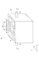
- FIG. 1 is a schematic cross-sectional view showing an example of a gas diffusion electrode according to an embodiment of the present invention.
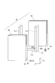
- FIG. 2 is a schematic perspective view showing an example of a microbial fuel cell according to an embodiment of the present invention.
- FIG. 3 is a cross-sectional view taken along line AA in FIG.
- FIG. 4 is an exploded perspective view showing a fuel cell unit in the microbial fuel cell.
- FIG. 5 is a graph showing the relationship between the power density and the elapsed days in the microbial fuel cell using the gas diffusion electrodes of Examples and Comparative Examples 1 and 2.
- the gas diffusion electrode 10 of the present embodiment is formed of a woven fabric or a nonwoven fabric, and has a water-repellent water-repellent layer 1 and an adhesive layer laminated on one surface 1 a of the water-repellent layer 1. 2 is provided. Further, the gas diffusion electrode 10 includes a gas diffusion layer 3 laminated on the surface 2b opposite to the surface 2a on the water repellent layer side in the adhesive layer 2.
- water repellent layer Since the water repellent layer 1 has water repellency, it separates a gas phase 5 described later from an electrolyte solution 70 as a liquid phase held in the waste water tank 80. And by providing the water repellent layer 1, it can suppress that the electrolyte solution 70 moves to the gaseous-phase 5 side.
- separation here means physical interruption
- the water repellent layer 1 is in contact with the gas phase 5 containing oxygen, diffuses the gas in the gas phase 5, and supplies the gas substantially uniformly to the surface 3 a of the gas diffusion layer 3. Therefore, the water repellent layer 1 is preferably a porous body so that the gas can be diffused. In addition, since the water repellent layer 1 has water repellency, it can suppress that the pore of a porous body obstruct
- the water repellent layer 1 is preferably formed in a sheet shape from a woven fabric or a non-woven fabric.
- the material constituting the water repellent layer 1 is not particularly limited as long as it has water repellency and can diffuse the gas in the gas phase 5.
- a material constituting the water repellent layer 1 for example, at least one selected from the group consisting of polyethylene, polypropylene, polybutadiene, nylon, polytetrafluoroethylene, ethyl cellulose, poly-4-methylpentene-1 and butyl rubber is used. be able to. Since these materials are easy to form a porous body and also have high water repellency, they can suppress clogging of pores and improve gas diffusibility.
- the water repellent layer 1 preferably has a plurality of through holes in the stacking direction X of the water repellent layer 1, the adhesive layer 2, and the gas diffusion layer 3.
- the water repellent layer 1 may be subjected to a water repellent treatment using a water repellent as necessary in order to enhance water repellency.
- a water repellent such as polytetrafluoroethylene (PTFE) may be attached to the porous body constituting the water repellent layer 1 to improve water repellency.
- PTFE polytetrafluoroethylene
- the water repellent layer 1 is preferably bonded to the gas diffusion layer 3 via the adhesive layer 2 as shown in FIG. That is, the surface 1 a of the water repellent layer 1 is preferably bonded to the surface 3 a of the gas diffusion layer 3 facing the adhesive layer 2. Thereby, the diffused gas is directly supplied to the surface 3a of the gas diffusion layer 3, and the oxygen reduction reaction can be performed efficiently.
- the gas diffusion electrode 10 of this embodiment includes a gas diffusion layer 3 having conductivity and oxygen permeability.
- a gas diffusion layer 3 having conductivity and oxygen permeability.
- electrons generated by a local cell reaction described later can be conducted between the catalyst layer 4 and the load circuit 90. That is, as will be described later, the catalyst layer 4 carries an oxygen reduction catalyst. Therefore, by providing the gas diffusion layer 3, electrons are supplied from the load circuit 90 to the oxygen reduction catalyst through the gas diffusion layer 3, so that the oxygen reduction reaction by oxygen, hydrogen ions, and electrons is promoted in the catalyst layer 4. Is possible.
- the gas diffusion layer 3 is preferably a porous body having many pores through which oxygen can pass.
- the shape of the gas diffusion layer 3 is particularly preferably a three-dimensional mesh. Such a mesh shape makes it possible to impart high oxygen permeability and conductivity to the gas diffusion layer 3.
- the conductor material constituting the gas diffusion layer 3 is not particularly limited as long as high conductivity can be secured.
- the conductor material is preferably made of at least one conductive metal selected from the group consisting of aluminum, copper, stainless steel, nickel and titanium. Since these conductive metals have high corrosion resistance and conductivity, they can be suitably used as a material constituting the gas diffusion layer 3.
- the conductor material constituting the gas diffusion layer 3 may be a carbon material.
- the carbon material for example, at least one selected from the group consisting of carbon paper, carbon felt, carbon cloth, and graphite sheet can be used.
- the conductor material may be made of one selected from the group consisting of carbon paper, carbon felt, carbon cloth, and graphite sheet, or may be a laminate formed by laminating a plurality of these.
- Carbon paper and carbon felt which are carbon fiber nonwoven fabrics, carbon cloth, which is carbon fiber woven fabric, and graphite sheets made of graphite have high corrosion resistance and electrical resistance equivalent to that of metal materials. It becomes possible to achieve both durability and conductivity.
- the above graphite sheet can be obtained as follows. First, natural graphite is chemically treated with an acid to form an insert between the graphite graphene layers. Next, this is rapidly heated at a high temperature to obtain expanded graphite in which the graphene interlayer is pushed and expanded by the gas pressure due to the thermal decomposition of the intercalated insert. Then, the expanded graphite is pressurized and roll-rolled to obtain a graphite sheet.
- the graphite sheet thus obtained is used as the gas diffusion layer 3
- the graphene layers in the graphite are arranged along the direction Y perpendicular to the stacking direction X. And the efficiency of the battery reaction can be further improved.
- the gas diffusion electrode 10 of this embodiment includes an adhesive layer 2 that joins the water-repellent layer 1 and the gas diffusion layer 3. That is, one surface 1 a of the water repellent layer 1 and the surface 3 a facing the surface 1 a of the gas diffusion layer 3 are bonded via the adhesive layer 2. And the contact bonding layer 2 does not have biodegradability, and has alkali resistance.
- the negative electrode 20 the ion permeable membrane 30, and the catalyst layer 4 of the positive electrode 40 are immersed in the electrolytic solution 70, and the adhesive layer 2 is the electrolytic solution. 70 is contacted.
- the contact bonding layer 2 contacts the microorganisms which exist in the electrolyte solution 70, in order to suppress decomposition
- protons are consumed in association with the oxygen reduction reaction, resulting in an increase in pH.
- the adhesive layer 2 of the positive electrode 40 is exposed to an alkaline environment, the adhesive layer 2 needs to have alkali resistance.
- the adhesive layer 2 since the adhesive layer 2 has biodegradability and alkali resistance, the adhesiveness between the water repellent layer 1 and the gas diffusion layer 3 is maintained for a long period of time. It is possible to suppress the electrolyte solution 70 from entering between the gas diffusion layer 3 and the gas diffusion layer 3. And by suppressing peeling between the water repellent layer 1 and the gas diffusion layer 3, it is possible to prevent the electrolytic solution 70 from entering the inside of the water repellent layer 1. While maintaining, water leakage from the water repellent layer 1 can be suppressed.
- the adhesive layer does not have biodegradability
- the resin constituting the adhesive layer 2 has a molecular structure that serves as a substrate for extracellular enzymes secreted from microorganisms. It means not. Specifically, it means that the resin constituting the adhesive layer 2 does not have the urethane bond shown in Chemical Formula 1 or the polyvinyl alcohol structure shown in Chemical Formula 2. Microorganisms contained in the electrolyte solution 70 secrete extracellular enzymes and have an action of decomposing urethane bonds and polyvinyl alcohol structures. Therefore, since the resin constituting the adhesive layer 2 does not have these molecular structures, the biodegradability can be improved.
- the alkali resistance of the adhesive layer 2 can be measured in accordance with ASTM standard D543. Specifically, first, a plate-shaped test piece having a length of 76.2 mm and a width of 25.4 mm is produced from the material constituting the adhesive layer 2. Next, the obtained test piece is immersed in a solution at 23 ⁇ 2 ° C. for 7 days. At this time, the amount of the solution is 10 ml or more per 1 in 2 of the test piece, and the test piece is suspended in the container so as not to touch the bottom surface and wall surface of the container holding the solution. The solution in the container is stirred every 24 hours.
- the mass, length, and thickness of the test piece are measured before and after the immersion, and the mass change rate M (%), the length change rate L (%), and the thickness change rate T (%) are measured from Equations 1 to 3. .
- the silicone rubber one-part RTV silicone rubber KE-3475-T manufactured by Shin-Etsu Chemical Co., Ltd.
- the rate of change T (%) is measured.
- the mass change rate, the length change rate, and the thickness change rate of the silicone rubber are each 1, a material in which the mass change rate, the length change rate, and the thickness change rate are all less than 1, Define.
- M 1 Mass of the test piece before immersion
- M 2 Mass of the test piece after immersion
- L 1 length in the longitudinal direction of the test piece before immersion
- L 2 length in the longitudinal direction of the test piece after immersion
- T 1 thickness of the test piece before immersion
- T 2 thickness of the test piece after immersion
- the adhesive layer 2 is preferably made of a resin that does not have biodegradability and has alkali resistance.
- the adhesive layer 2 is made of a resin containing at least one selected from the group consisting of polymethyl methacrylate, methacrylic acid-styrene copolymer, styrene-butadiene rubber, butyl rubber, nitrile rubber, and chloroprene rubber. preferable.
- the adhesive layer 2 is made of polyvinyl chloride, polyvinylidene chloride, polystyrene, styrene-acrylonitrile copolymer, styrene-butadiene-acrylonitrile copolymer, polyethylene, ethylene-vinyl acetate copolymer, polypropylene, polyacetal copolymer, It is preferably made of a resin containing at least one selected from the group consisting of polymethyl methacrylate, polyethylene terephthalate, epoxy resin, ethylene-propylene rubber, chlorosulfonated polyethylene, and ethylene-vinyl acetate rubber.
- the adhesive layer 2 needs to be provided at least at a part between the water-repellent layer 1 and the gas diffusion layer 3 from the viewpoint of ensuring the adhesiveness between the water-repellent layer 1 and the gas diffusion layer 3. .
- the adhesive layer 2 is formed between the water repellent layer 1 and the gas diffusion layer 3. It is preferable to be provided over the entire surface.
- the gas diffusion electrode 10 of the present embodiment preferably further includes a catalyst layer 4 laminated on a surface 3 b opposite to the surface 3 a on the adhesive layer 2 side in the gas diffusion layer 3.
- a catalyst layer 4 laminated on a surface 3 b opposite to the surface 3 a on the adhesive layer 2 side in the gas diffusion layer 3.
- the catalyst layer 4 preferably contains an oxygen reduction catalyst.
- the reaction rate between oxygen and hydrogen ions transferred by the water repellent layer 1, the adhesive layer 2, and the gas diffusion layer 3 can be further increased.
- the catalyst layer 4 preferably has oxygen permeability, that is, has a large number of voids (pores) through which oxygen can permeate.
- the catalyst layer 4 preferably uses a binder for binding the oxygen reduction catalyst particles together to form a porous body. Such a binder is not particularly limited as long as particles can be bound to each other.
- binder for example, at least one selected from the group consisting of polytetrafluoroethylene (PTFE), polyvinylidene fluoride (PVDF), and ethylene-propylene-diene copolymer (EPDM) is preferably used.
- PTFE polytetrafluoroethylene
- PVDF polyvinylidene fluoride
- EPDM ethylene-propylene-diene copolymer
- the oxygen reduction catalyst is preferably a carbon-based material doped with metal atoms. Although it does not specifically limit as a metal atom, Titanium, vanadium, chromium, manganese, iron, cobalt, nickel, copper, zirconium, niobium, molybdenum, ruthenium, rhodium, palladium, silver, hafnium, tantalum, tungsten, rhenium, osmium, iridium , Preferably an atom of at least one metal selected from the group consisting of platinum and gold.
- the carbon-based material exhibits excellent performance particularly as a catalyst for promoting the oxygen reduction reaction. What is necessary is just to set suitably the quantity of the metal atom which carbonaceous material contains so that carbonaceous material may have the outstanding catalyst performance.
- the carbon-based material is further doped with one or more nonmetallic atoms selected from nitrogen, boron, sulfur, and phosphorus. What is necessary is just to set suitably the quantity of the nonmetallic atom doped by the carbonaceous material so that carbonaceous material may have the outstanding catalyst performance.
- the carbon-based material is based on a carbon source material such as graphite and amorphous carbon, for example, and the carbon source material is doped with a metal atom and one or more non-metal atoms selected from nitrogen, boron, sulfur and phosphorus. Can be obtained.
- a carbon source material such as graphite and amorphous carbon, for example, and the carbon source material is doped with a metal atom and one or more non-metal atoms selected from nitrogen, boron, sulfur and phosphorus. Can be obtained.
- the combination of metal atoms and nonmetal atoms doped in the carbon-based material is appropriately selected.
- the nonmetallic atom contains nitrogen and the metallic atom contains iron.
- the carbon-based material can have particularly excellent catalytic activity.
- the nonmetallic atom may be only nitrogen. Further, the metal atom may be only iron.
- the nonmetallic atom may contain nitrogen, and the metallic atom may contain at least one of cobalt and manganese. Also in this case, the carbon-based material can have a particularly excellent catalytic activity.
- the nonmetallic atom may be only nitrogen. Further, the metal atom may be only cobalt, only manganese, or only cobalt and manganese.
- a carbon-based material configured as an oxygen reduction catalyst can be prepared as follows. First, for example, a mixture containing a nonmetallic compound containing at least one nonmetal selected from the group consisting of nitrogen, boron, sulfur, and phosphorus, a metal compound, and a carbon source material is prepared. And this mixture is heated at the temperature of 800 degreeC or more and 1000 degrees C or less for 45 second or more and less than 600 second. Thereby, the carbonaceous material comprised as an oxygen reduction catalyst can be obtained.
- the carbon source material for example, graphite or amorphous carbon can be used as described above.
- the metal compound is not particularly limited as long as it is a compound containing a metal atom capable of coordinating with a nonmetal atom doped in the carbon source material.
- Metal compounds include, for example, metal chlorides, nitrates, sulfates, bromides, iodides, fluorides, etc .; inorganic metal salts such as acetates; inorganic metal salt hydrates; and organic metal salts At least one selected from the group consisting of hydrates can be used.
- the metal compound preferably contains iron (III) chloride.
- the metal compound when graphite is doped with cobalt, the metal compound preferably contains cobalt chloride.
- the metal compound when the carbon source material is doped with manganese, the metal compound preferably contains manganese acetate.
- the amount of the metal compound used is preferably set so that, for example, the ratio of the metal atom in the metal compound to the carbon source material is in the range of 5 to 30% by mass, and this ratio is in the range of 5 to 20% by mass. It is more preferable to set so as to be within.
- the nonmetallic compound is preferably at least one nonmetallic compound selected from the group consisting of nitrogen, boron, sulfur and phosphorus.
- Non-metallic compounds include, for example, pentaethylenehexamine, ethylenediamine, tetraethylenepentamine, triethylenetetramine, ethylenediamine, octylboronic acid, 1,2-bis (diethylphosphinoethane), triphenyl phosphite, benzyldisal
- At least one compound selected from the group consisting of fido can be used.
- the amount of the nonmetallic compound used is appropriately set according to the amount of the nonmetallic atom doped into the carbon source material.
- the amount of the nonmetallic compound used is preferably set so that the molar ratio of the metal atom in the metal compound to the nonmetallic atom in the nonmetallic compound is within the range of 1: 1 to 1: 2. : It is more preferable to set it within the range of 1.5 to 1: 1.8.
- a mixture containing a nonmetallic compound, a metal compound, and a carbon source material when preparing a carbon-based material configured as an oxygen reduction catalyst is obtained, for example, as follows. First, a carbon source material, a metal compound, and a nonmetal compound are mixed, and if necessary, a solvent such as ethanol is added to adjust the total amount. These are further dispersed by an ultrasonic dispersion method. Subsequently, after heating them at an appropriate temperature (for example, 60 ° C.), the mixture is dried to remove the solvent. Thereby, the mixture containing a nonmetallic compound, a metal compound, and a carbon source raw material is obtained.
- the obtained mixture is heated, for example, under a reducing atmosphere or an inert gas atmosphere.
- a non-metallic atom is doped to a carbon source raw material, and also a metallic atom is doped by the coordinate bond of a non-metallic atom and a metallic atom.
- the heating temperature is preferably in the range of 800 ° C. to 1000 ° C.
- the heating time is preferably in the range of 45 seconds to less than 600 seconds. Since the heating time is short, the carbon-based material is efficiently produced, and the catalytic activity of the carbon-based material is further increased.
- the temperature rising rate of the mixture at the start of heating is preferably 50 ° C./s or more. Such rapid heating further improves the catalytic activity of the carbon-based material.
- the carbon-based material may be further acid cleaned.
- the carbon-based material may be dispersed in pure water with a homogenizer for 30 minutes, and then the carbon-based material may be placed in 2M sulfuric acid and stirred at 80 ° C. for 3 hours. In this case, elution of the metal component from the carbon-based material can be suppressed.
- the gas diffusion electrode 10 for a microbial fuel cell of the present embodiment is formed of a woven fabric or a non-woven fabric, and has a water-repellent water-repellent layer 1 and an adhesive layer laminated on one surface of the water-repellent layer 1. 2 is provided. Further, the gas diffusion electrode 10 includes a gas diffusion layer 3 laminated on a surface 2 b opposite to the surface 2 a on the water repellent layer 1 side in the adhesive layer 2. And the contact bonding layer 2 does not have biodegradability, and has alkali resistance.
- the adhesive layer 2 Since the adhesive layer 2 has biodegradation resistance against microorganisms present in the electrolytic solution 70 and also has alkali resistance, the adhesiveness between the water repellent layer 1 and the gas diffusion layer 3 is maintained for a long period of time. . Therefore, since the electrolyte solution 70 is prevented from entering the water repellent layer 1, water leakage from the water repellent layer 1 can be suppressed for a long period of time. In addition, since the high gas permeability and gas diffusibility of the water repellent layer 1 can be maintained, a high output can be obtained over a long period of time.
- the manufacturing method of the gas diffusion electrode 10 has the process of joining the water-repellent layer 1 and the gas diffusion layer 3 with the contact bonding layer 2, another process will not be specifically limited.
- an adhesive constituting the adhesive layer 2 is applied to the surface 1 a of the water repellent layer 1.
- a coating method is not particularly limited, and a known method can be used.
- the surface 3a of the gas diffusion layer 3 is brought into contact with the applied adhesive, pressed as necessary, and then the adhesive is cured, so that the water repellent layer 1 and the gas diffusion layer 3 are joined by the adhesive layer 2. be able to.
- coating an adhesive agent to the surface 3a of the gas diffusion layer 3 you may make the surface 1a of the water-repellent layer 1 contact an adhesive agent.
- the production method of the catalyst layer 4 is not particularly limited, and can be produced, for example, as follows.
- a catalyst slurry is prepared by mixing an oxygen reduction catalyst and a binder in a solvent.
- the mixing amount of the oxygen reduction catalyst and the binder is preferably adjusted as appropriate according to the thickness of the catalyst layer.
- the solvent used in preparing the slurry is not particularly limited, and examples thereof include water, alcohol solvents such as methanol, ethanol, 1-propanol, 2-propanol, ethylene glycol, and propylene glycol.
- the catalyst layer 4 can be formed by directly applying the catalyst slurry to the surface 3b of the gas diffusion layer 3 and compressing and drying or firing. In this case, since the catalyst slurry is directly applied to the gas diffusion layer 3, the contact area between the gas diffusion layer 3 and the catalyst layer 4 can be increased.
- the microbial fuel cell 100 of the present embodiment is separated from the negative electrode 20 via the ion permeable membrane 30, the ion permeable membrane 30 that transmits hydrogen ions, and the negative electrode 20 that supports microorganisms.
- the positive electrode 40 made of the gas diffusion electrode 10 described above.
- the negative electrode 20 is disposed so as to contact one surface 30 a of the ion permeable membrane 30, and the positive electrode 40 contacts the surface 30 b opposite to the surface 30 a of the ion permeable membrane 30. Is arranged.
- the negative electrode 20 has a structure in which microorganisms are supported on a conductive sheet having conductivity.
- the conductor sheet it is possible to use at least one selected from the group consisting of a porous conductor sheet, a woven conductor sheet, and a nonwoven conductor sheet.
- the conductor sheet may be a laminate in which a plurality of sheets are laminated.
- the conductor sheet of the negative electrode 20 has a space (void) continuous in the stacking direction X of the positive electrode 40, the ion permeable film 30 and the negative electrode 20, that is, in the thickness direction. It is preferable.
- the conductor sheet may be a metal plate having a plurality of through holes in the thickness direction. Therefore, as a material constituting the conductor sheet of the negative electrode 20, for example, at least one selected from the group consisting of conductive metals such as aluminum, copper, stainless steel, nickel and titanium, carbon paper, and carbon felt is used. be able to.
- the conductor sheet of the negative electrode 20 a gas diffusion layer used in the gas diffusion electrode 10 may be used.
- the negative electrode 20 preferably contains graphite, and the graphene layer in the graphite is preferably arranged along a plane in a direction YZ perpendicular to the stacking direction X of the positive electrode 40, the ion permeable film 30 and the negative electrode 20.
- the conductivity in the direction YZ perpendicular to the stacking direction X is improved as compared with the conductivity in the stacking direction X. Therefore, it becomes easy to conduct the electrons generated by the local battery reaction of the negative electrode 20 to the load circuit, and the efficiency of the battery reaction can be further improved.
- the microorganism supported on the negative electrode 20 is not particularly limited as long as it is a microorganism that decomposes an organic substance in the electrolyte solution 70 or a compound containing nitrogen.
- a microorganism that decomposes an organic substance in the electrolyte solution 70 or a compound containing nitrogen is used.
- an anaerobic microorganism that does not require oxygen for growth is used.
- Anaerobic microorganisms do not require air for oxidizing and decomposing organic substances in the electrolyte solution 70. Therefore, the electric power required for sending air can be significantly reduced.
- the free energy which microbes acquire is small, it becomes possible to reduce the amount of sludge generation.
- the anaerobic microorganism held in the negative electrode 20 is preferably an electricity producing bacterium having an extracellular electron transfer mechanism, for example.
- examples of the anaerobic microorganism include Geobacter genus bacteria, Shewanella genus bacteria, Aeromonas genus bacteria, Geothrix genus bacteria, and Saccharomyces genus bacteria.
- Anaerobic microorganisms may be held on the negative electrode 20 by superimposing and fixing a biofilm containing anaerobic microorganisms on the negative electrode 20.
- the biofilm generally refers to a three-dimensional structure including a microbial population and an extracellular polymeric substance (EPS) produced by the microbial population.
- EPS extracellular polymeric substance
- the anaerobic microorganisms may be held on the negative electrode 20 without depending on the biofilm.
- the anaerobic microorganisms may be held not only on the surface of the negative electrode 20 but also inside.
- the microbial fuel cell 100 of the present embodiment includes an ion permeable membrane 30 that transmits hydrogen ions.
- the ion permeable membrane 30 has a function of transmitting hydrogen ions generated by the negative electrode 20 and moving the hydrogen ions to the positive electrode 40 side.
- an ion exchange membrane using an ion exchange resin can be used as the ion permeable membrane 30.
- the ion exchange resin for example, NAFION (registered trademark) manufactured by DuPont, and Flemion (registered trademark) and Selemion (registered trademark) manufactured by Asahi Glass Co., Ltd. can be used.
- the ion permeable membrane 30 a porous membrane having pores that can permeate hydrogen ions may be used.
- the ion permeable membrane 30 may be a sheet having a space (void) for hydrogen ions to move between the negative electrode 20 and the positive electrode 40. Therefore, the ion permeable membrane 30 preferably includes at least one selected from the group consisting of a porous sheet, a woven sheet, and a non-woven sheet.
- the ion permeable film 30 can use at least one chosen from the group which consists of a glass fiber film, a synthetic fiber film, and a plastic nonwoven fabric, and the laminated body formed by laminating
- the pore diameter of the ion permeable membrane 30 is not particularly limited as long as hydrogen ions can move from the negative electrode 20 to the positive electrode 40.
- the microbial fuel cell 100 of the present embodiment includes a positive electrode 40 made of the gas diffusion electrode 10 described above. That is, the positive electrode 40 is formed of a woven fabric or a non-woven fabric and includes a water-repellent water-repellent layer 1 and an adhesive layer 2 laminated on one surface of the water-repellent layer 1. Further, the positive electrode 40 includes a gas diffusion layer 3 laminated on a surface 2 b opposite to the surface 2 a on the water repellent layer 1 side in the adhesive layer 2. An ion permeable membrane 30 is provided on the surface 4 a side of the catalyst layer 4.
- the microbial fuel cell 100 includes a plurality of membrane electrode assemblies 50 including a positive electrode 40, an ion permeable membrane 30, and a negative electrode 20, as shown in FIGS. 2 and 3. Further, the two membrane electrode assemblies 50 are laminated via the cassette base 51 so that the positive electrodes 40 face each other. As shown in FIG. 4, the cassette base 51 is a U-shaped frame member along the outer periphery of the positive electrode 40, and the upper part is open. That is, the cassette base 51 is a frame member in which the bottom surfaces of the two first columnar members 51a are connected by the second columnar member 51b.
- the side surface 51 c of the cassette base 51 is joined to the outer peripheral portion of the surface 40 a opposite to the ion permeable membrane 30 in the positive electrode 40, and the electrolytic solution 70 enters the cassette base 51 from the outer peripheral portion of the positive electrode 40. Can be prevented from leaking.
- the fuel cell unit 60 formed by laminating the two membrane electrode assemblies 50 and the cassette base material 51 has a waste water tank so that a gas phase 5 communicating with the atmosphere is formed. 80 is arranged inside.
- An electrolytic solution 70 is held inside the waste water tank 80, and the negative electrode 20, the ion permeable membrane 30, and the catalyst layer 4 of the positive electrode 40 are immersed in the electrolytic solution 70. That is, the water repellent layer 1 constituting the positive electrode 40 is disposed so as to be in contact with a gas containing oxygen, and the catalyst layer 4 is disposed so as to be in contact with the electrolytic solution 70.
- the water repellent layer 1 of the positive electrode 40 has water repellency. Therefore, the electrolytic solution 70 held in the waste water tank 80 is separated from the inside of the cassette base 51, and the internal space formed by the two membrane electrode assemblies 50 and the cassette base 51 is a gas phase 5. It has become. As shown in FIG. 3, the positive electrode 40 and the negative electrode 20 are electrically connected to the load circuit 90, respectively.
- the negative electrode 20 is in contact with one surface 30a of the ion permeable membrane 30, and the positive electrode 40 is provided on the surface 30b opposite to the surface 30a of the ion permeable membrane 30.
- the negative electrode 20 is not necessarily in contact with the surface 30 a of the ion permeable membrane 30.
- the positive electrode 40 is not necessarily in contact with the surface 30 b of the ion permeable membrane 30.
- the negative electrode 20, the ion permeable film 30, and the positive electrode 40 may be arranged so that hydrogen ions generated in the negative electrode 20 can pass through the ion permeable film 30 and move to the positive electrode 40. Therefore, a gap may exist between the negative electrode 20 and the ion permeable film 30, and a gap may exist between the positive electrode 40 and the ion permeable film 30.
- the waste water tank 80 holds the electrolytic solution 70 therein, but may be configured such that the electrolytic solution 70 circulates.
- a liquid supply port 81 for supplying the electrolytic solution 70 to the wastewater tank 80 and a discharged electrolytic solution 70 from the wastewater tank 80 are discharged.
- the liquid discharge port 82 may be provided.
- the inside of the wastewater tank 80 is maintained under anaerobic conditions in which, for example, molecular oxygen is not present or even if molecular oxygen is present, the concentration thereof is extremely small. Thereby, it becomes possible to hold
- the electrolyte solution 70 is supplied to the negative electrode 20, and air (or oxygen) is supplied to the positive electrode 40.
- the electrolytic solution 70 contains at least an organic substance, but may further contain a nitrogen-containing compound. Air is continuously supplied through an opening provided in the upper part of the cassette base 51.
- the electrolyte solution 70 is also preferably supplied continuously through the liquid supply port 81 and the liquid discharge port 82.
- the positive electrode 40 air is diffused by the water repellent layer 1, oxygen in the air passes through the adhesive layer 2 and the gas diffusion layer 3, and reaches the catalyst layer 4.
- hydrogen ions and electrons are generated from organic substances and / or nitrogen-containing compounds in the electrolytic solution 70 by the catalytic action of microorganisms.
- the generated hydrogen ions pass through the ion permeable membrane 30 and move to the positive electrode 40 side.
- the generated electrons move to the load circuit 90 through the conductor sheet of the negative electrode 20, and further move from the load circuit 90 to the catalyst layer 4 through the gas diffusion layer 3 of the positive electrode 40.
- the hydrogen ions and electrons that have moved to the catalyst layer 4 are combined with oxygen by the action of the oxygen reduction catalyst in the catalyst layer 4 and consumed as water. At this time, the load circuit 90 recovers the electric energy flowing in the closed circuit.
- the water-repellent layer 1 and the gas diffusion layer 3 are joined by the adhesive layer 2 that is not biodegradable and has alkali resistance.
- the adhesive layer 2 is hardly deteriorated by microorganisms or an alkaline atmosphere present in the electrolytic solution 70, and thus the adhesiveness between the water repellent layer 1 and the gas diffusion layer 3 is maintained for a long period of time. Therefore, since the electrolytic solution 70 is prevented from entering the water repellent layer 1, water leakage from the water repellent layer 1 can be suppressed.
- the high gas permeability and gas diffusibility of the water repellent layer 1 can be maintained, it is possible to efficiently supply oxygen to the catalyst layer 4 and obtain a high output over a long period of time.
- the negative electrode 20 may be modified with, for example, an electron transfer mediator molecule.
- the electrolytic solution 70 in the waste water tank 80 may contain electron transfer mediator molecules. Thereby, the electron transfer from an anaerobic microorganism to the negative electrode 20 is accelerated
- an electron transfer mediator molecule is not particularly limited.
- the electron transfer mediator molecule for example, at least one selected from the group consisting of neutral red, anthraquinone-2,6-disulfonic acid (AQDS), thionine, potassium ferricyanide, and methylviologen can be used.
- the fuel cell unit 60 shown in FIGS. 2 and 3 has a configuration in which two membrane electrode assemblies 50 and a cassette base 51 are stacked.
- the present embodiment is not limited to this configuration.
- the membrane electrode assembly 50 may be bonded to only one side surface 51c of the cassette base 51 and the other side surface may be sealed with a plate member. 2 and 3, the entire upper portion of the cassette base 51 is open, but may be partially open if air (oxygen) can be introduced into the interior, It may be closed.
- an acrylic resin was applied to one surface of a polyolefin water-repellent layer to form an adhesive layer, and then a carbon cloth as a gas diffusion layer was laminated to adhere the carbon cloth to the water-repellent layer.
- the polyolefin water-repellent layer used was DuPont Tyvek (registered trademark).
- As the acrylic resin ACRICID (registered trademark) WAL578 manufactured by DIC Corporation was used.
- the catalyst layer was formed by apply
- an ionomer Aciplex (registered trademark) manufactured by Asahi Kasei Corporation was used. Thus, the gas diffusion electrode of this example was obtained.
- the microbial fuel cell was produced using the positive electrode which consists of the obtained gas diffusion electrode. Specifically, first, a positive electrode in which an air intake portion was provided in the water repellent layer of the gas diffusion electrode and a negative electrode made of a stainless steel mesh substrate were installed in a wastewater tank. And the nonwoven fabric was installed between the positive electrode and the negative electrode, and the electrolyte solution was filled in the waste water tank so that a positive electrode, a negative electrode, and a nonwoven fabric might be touched.
- the electrolytic solution contained an organic substance having a total organic carbon (TOC) of 800 mg / L, and soil microorganisms were inoculated as an anaerobic microorganism source for power generation. The amount of inflow into the wastewater tank was adjusted so that the hydraulic retention time of the electrolyte was 24 hours. And the microbial fuel cell of this example was obtained by connecting a positive electrode and a negative electrode to a load circuit.
- TOC total organic carbon
- a gas diffusion electrode of this example was obtained in the same manner as in Example except that urethane resin was used instead of acrylic resin as the adhesive layer in the gas diffusion electrode.
- the urethane resin used was a mixture of ACRICID (registered trademark) 52-666-BA manufactured by DIC Corporation and Takenate (registered trademark) D-160N manufactured by Mitsui Chemicals Co., Ltd. at a ratio of 5: 2. .
- the microbial fuel cell of this example was obtained in the same manner as in the example using the obtained positive electrode composed of the gas diffusion electrode.
- a gas diffusion electrode of this example was obtained in the same manner as in the example except that a silicone resin was used instead of an acrylic resin as an adhesive layer in the gas diffusion electrode.
- a silicone resin one-component RTV silicone rubber KE-3475-T manufactured by Shin-Etsu Chemical Co., Ltd. was used.
- the microbial fuel cell of this example was obtained in the same manner as in the example using the obtained positive electrode composed of the gas diffusion electrode.
- Examples and Comparative Examples 1 and 2 were obtained immediately after the output was stabilized and after 60 days of operation.
- the output after 60 days of operation was divided by the output immediately after stabilization to determine the maintenance rate.
- Table 1 shows the output immediately after stabilization, the output after 60 days of operation, and the maintenance rate in Examples and Comparative Examples 1 and 2.
- the microbial fuel cell of Comparative Example 1 uses an adhesive layer made of a urethane resin having low biodegradability. Therefore, it is considered that with the operation of the microbial fuel cell, microorganisms proliferated and decomposed the adhesive layer, and separation occurred between the water-repellent layer and the gas diffusion layer. When peeling occurs, an electrolytic solution enters between the water repellent layer and the gas diffusion layer, and the diffusion rate of oxygen in the gas phase decreases. Therefore, it is considered that the characteristics of the positive electrode deteriorate and the output of the microbial fuel cell decreases. In addition, since this peeling expands with time, the output of the microbial fuel cell of Comparative Example 1 is lower than that immediately after stabilization after 60 days of operation, and the output maintenance rate is deteriorated.
- the microbial fuel cell of Comparative Example 2 uses an adhesive layer made of a silicone resin having low alkali resistance.
- proton consumption accompanying the oxygen reduction reaction that is, an increase in pH occurs.
- the adhesive layer of the positive electrode is exposed to an alkaline environment, so that it is considered that peeling occurred between the water repellent layer and the gas diffusion layer.
- this peeling expands with time, the output of the microbial fuel cell of Comparative Example 2 is lower than that immediately after stabilization after 60 days of operation, and the output maintenance rate is deteriorated.
- the microbial fuel cell of the example uses an acrylic resin having high biodegradability and alkali resistance. Therefore, it is considered that high output was maintained by suppressing the separation between the water repellent layer and the gas diffusion layer generated in Comparative Examples 1 and 2.
- the present embodiment has been described above, the present embodiment is not limited to these, and various modifications are possible within the scope of the gist of the present embodiment.
- the gas diffusion electrode 10 provided with the water repellent layer 1, the adhesive layer 2, the gas diffusion layer 3, and the catalyst layer 4, and the negative electrode 20, the ion permeable membrane 30 and the positive electrode 40 are formed in a rectangular shape.
- these shapes are not particularly limited, and can be arbitrarily changed depending on the size of the fuel cell and the desired power generation performance. Further, the area of each layer can be arbitrarily changed as long as a desired function can be exhibited.
- the adhesion between the water repellent layer and the gas diffusion layer is enhanced by the predetermined adhesive layer, water leakage from the water repellent layer can be suppressed over a long period of time.
- the microbial fuel cell using the gas diffusion electrode can maintain a high output for a long time.
Abstract
A gas diffusion electrode (10) is formed of a woven or nonwoven textile, and is provided with a water repellent layer (1) having water repellency, and an adhesion layer (2) laminated on one surface of the water repellent layer. The gas diffusion electrode is additionally provided with a gas diffusion layer (3) that is laminated on the surface of the adhesion layer on the opposite side from the surface facing the water repellent layer. The adhesion layer is non-biodegradable, and is alkali-resistant. A microbial fuel cell (100) is provided with a negative electrode (20) for supporting microbes, an ion-permeable membrane (30) that is permeable with respect to hydrogen ions, and a positive electrode (40) comprising the gas diffusion electrode, the positive electrode (40) being separated from the negative electrode by the ion-permeable membrane.
Description
本発明は、微生物燃料電池用ガス拡散電極、及びそれを用いた微生物燃料電池に関する。詳細には本発明は、廃水を浄化し、かつ、電気エネルギーを生成することが可能な微生物燃料電池用ガス拡散電極、及びそれを用いた微生物燃料電池に関する。
The present invention relates to a gas diffusion electrode for a microbial fuel cell and a microbial fuel cell using the same. More particularly, the present invention relates to a gas diffusion electrode for a microbial fuel cell that can purify wastewater and generate electrical energy, and a microbial fuel cell using the same.
近年、持続可能なエネルギーとして、バイオマスを利用して発電をする微生物燃料電池が注目されている。微生物燃料電池は、生活廃水や工場廃水に含まれる有機性物質の化学エネルギーを電気エネルギーに変換しつつ、その有機性物質を酸化分解して処理する廃水処理装置である。そして、微生物燃料電池は、汚泥の発生が少なく、さらにエネルギー消費が少ない特徴を有する。ただ、微生物が発する電力が非常に小さく、出力される電流密度が低いため、更なる改良が必要である。
In recent years, microbial fuel cells that generate electricity using biomass have attracted attention as sustainable energy. A microbial fuel cell is a wastewater treatment apparatus that converts the chemical energy of an organic substance contained in domestic wastewater or factory wastewater into electrical energy and oxidizes and decomposes the organic substance. The microbial fuel cell is characterized by little generation of sludge and low energy consumption. However, since the power generated by microorganisms is very small and the output current density is low, further improvement is necessary.
微生物燃料電池は、微生物を担持する負極と、酸素を含む気相及び電解液に接触する正極とを有する。そして、有機性物質などを含有する電解液を負極に供給するとともに、酸素を含んだ気体を正極に供給する。負極及び正極は、負荷回路を介して相互に接続することにより閉回路を形成する。負極では、微生物の触媒作用により電解液から水素イオン及び電子が生成する。そして、生成した水素イオンは正極へ移動し、電子は負荷回路を介して正極へ移動する。負極から移動した水素イオン及び電子は正極において酸素と結合し、水となって消費される。その際に、閉回路に流れる電気エネルギーを回収する。
The microbial fuel cell has a negative electrode supporting microorganisms, and a positive electrode in contact with a gas phase containing oxygen and an electrolytic solution. And while supplying the electrolyte solution containing an organic substance etc. to a negative electrode, the gas containing oxygen is supplied to a positive electrode. The negative electrode and the positive electrode are connected to each other through a load circuit to form a closed circuit. In the negative electrode, hydrogen ions and electrons are generated from the electrolytic solution by the catalytic action of microorganisms. And the produced | generated hydrogen ion moves to a positive electrode, and an electron moves to a positive electrode through a load circuit. Hydrogen ions and electrons transferred from the negative electrode are combined with oxygen at the positive electrode and consumed as water. At that time, the electric energy flowing in the closed circuit is recovered.
ここで、正極は電解液と酸素を分離する必要があるため、撥水性が要求されている。また、正極内で漏水が生じた場合、酸素の拡散速度の減少による電流生成能の低下が起こるため、正極は長期に亘り漏水が生じ難いことが求められている。このような正極に用いられ得るガス拡散電極として、従来、ガス拡散電極基材の撥水処理を施したい部分に、ポリテトラフルオロエチレンなどのフッ素含有化合物を含む撥水材を形成することが開示されている(例えば、特許文献1参照)。そして、当該撥水材は、乾式噴霧法によりフッ素含有化合物を成膜することで形成されることが開示されている。
Here, since the positive electrode needs to separate the electrolyte and oxygen, water repellency is required. In addition, when water leakage occurs in the positive electrode, the current generation ability is reduced due to a decrease in the diffusion rate of oxygen. Therefore, it is demanded that the positive electrode is difficult to cause water leakage over a long period of time. Conventionally, as a gas diffusion electrode that can be used for such a positive electrode, it is disclosed that a water repellent material containing a fluorine-containing compound such as polytetrafluoroethylene is formed on a portion of the gas diffusion electrode base material where water repellent treatment is desired. (For example, refer to Patent Document 1). And it is disclosed that the water repellent material is formed by depositing a fluorine-containing compound by a dry spray method.
上述のように、特許文献1のガス拡散電極は、ポリテトラフルオロエチレンなどのフッ素含有化合物の粉末を乾式噴霧することで成膜している。そのため、得られる撥水材にはクラックやピンホールが生じ易い。特に、このようなガス拡散電極を大面積化した場合には、クラック等の発生による漏水が生じ易く、その結果、酸素の拡散速度が著しく減少して燃料電池の出力が低下する恐れがあった。
As described above, the gas diffusion electrode of Patent Document 1 is formed by dry spraying a powder of a fluorine-containing compound such as polytetrafluoroethylene. Therefore, cracks and pinholes are likely to occur in the obtained water repellent material. In particular, when such a gas diffusion electrode is enlarged, water leakage due to the occurrence of cracks or the like is likely to occur, and as a result, the oxygen diffusion rate may be significantly reduced and the output of the fuel cell may be reduced. .
本発明は、このような従来技術の有する課題に鑑みてなされたものである。そして、本発明の目的は、長期間に亘り撥水層からの漏水を抑制し、高出力を維持することが可能な微生物燃料電池用ガス拡散電極、及びそれを用いた微生物燃料電池を提供することにある。
The present invention has been made in view of such problems of the conventional technology. And the objective of this invention provides the gas diffusion electrode for microbial fuel cells which can suppress the water leakage from a water repellent layer over a long period of time, and can maintain a high output, and a microbial fuel cell using the same There is.
上記課題を解決するために、本発明の第一の態様に係る微生物燃料電池用ガス拡散電極は、織布又は不織布で形成され、撥水性を有する撥水層と、撥水層の一方の面に積層された接着層とを備える。さらに当該ガス拡散電極は、接着層における撥水層側の面と反対側の面に積層されたガス拡散層を備える。そして、接着層は、生分解性を有さず、かつ、耐アルカリ性を有する。
In order to solve the above problems, a gas diffusion electrode for a microbial fuel cell according to a first aspect of the present invention is formed of a woven fabric or a nonwoven fabric and has a water-repellent water-repellent layer and one surface of the water-repellent layer. And an adhesive layer laminated to each other. The gas diffusion electrode further includes a gas diffusion layer laminated on the surface of the adhesive layer opposite to the surface on the water repellent layer side. The adhesive layer does not have biodegradability and has alkali resistance.
本発明の第二の態様に係る微生物燃料電池は、微生物を担持する負極と、水素イオンを透過するイオン透過膜と、イオン透過膜を介して負極と隔てられた、微生物燃料電池用ガス拡散電極からなる正極とを備える。
A microbial fuel cell according to a second aspect of the present invention includes a negative electrode carrying microorganisms, an ion permeable membrane that transmits hydrogen ions, and a gas diffusion electrode for a microbial fuel cell that is separated from the negative electrode through the ion permeable membrane. The positive electrode which consists of.
以下、本実施形態に係る微生物燃料電池用ガス拡散電極、及びそれを用いた微生物燃料電池について詳細に説明する。なお、図面の寸法比率は説明の都合上誇張されており、実際の比率とは異なる場合がある。
Hereinafter, the gas diffusion electrode for a microbial fuel cell according to the present embodiment and the microbial fuel cell using the same will be described in detail. In addition, the dimension ratio of drawing is exaggerated on account of description, and may differ from an actual ratio.
[ガス拡散電極]
本実施形態のガス拡散電極10は、図1に示すように、織布又は不織布で形成され、撥水性を有する撥水層1と、撥水層1の一方の面1aに積層された接着層2とを備える。さらにガス拡散電極10は、接着層2における撥水層側の面2aと反対側の面2bに積層されたガス拡散層3を備える。 [Gas diffusion electrode]
As shown in FIG. 1, thegas diffusion electrode 10 of the present embodiment is formed of a woven fabric or a nonwoven fabric, and has a water-repellent water-repellent layer 1 and an adhesive layer laminated on one surface 1 a of the water-repellent layer 1. 2 is provided. Further, the gas diffusion electrode 10 includes a gas diffusion layer 3 laminated on the surface 2b opposite to the surface 2a on the water repellent layer side in the adhesive layer 2.
本実施形態のガス拡散電極10は、図1に示すように、織布又は不織布で形成され、撥水性を有する撥水層1と、撥水層1の一方の面1aに積層された接着層2とを備える。さらにガス拡散電極10は、接着層2における撥水層側の面2aと反対側の面2bに積層されたガス拡散層3を備える。 [Gas diffusion electrode]
As shown in FIG. 1, the
(撥水層)
撥水層1は、撥水性を有しているため、後述する気相5と、廃水槽80の内部に保持された液相としての電解液70とを分離する。そして、撥水層1を設けることで、電解液70が気相5側に移動することを抑制できる。なお、ここでいう「分離」とは、物理的に遮断することをいう。 (Water repellent layer)
Since thewater repellent layer 1 has water repellency, it separates a gas phase 5 described later from an electrolyte solution 70 as a liquid phase held in the waste water tank 80. And by providing the water repellent layer 1, it can suppress that the electrolyte solution 70 moves to the gaseous-phase 5 side. In addition, "separation" here means physical interruption | blocking.
撥水層1は、撥水性を有しているため、後述する気相5と、廃水槽80の内部に保持された液相としての電解液70とを分離する。そして、撥水層1を設けることで、電解液70が気相5側に移動することを抑制できる。なお、ここでいう「分離」とは、物理的に遮断することをいう。 (Water repellent layer)
Since the
また、撥水層1は、酸素を含む気相5と接触しており、気相5中の気体を拡散し、ガス拡散層3の面3aに対し気体を略均一に供給している。そのため、撥水層1は、当該気体を拡散できるように、多孔質体であることが好ましい。なお、撥水層1が撥水性を有するため、結露等により多孔質体の細孔が閉塞し、気体の拡散性が低下することを抑制できる。そして、後述するように、ガス拡散電極10を燃料電池に用いた場合、撥水層1の内部に電解液70が染み込み難くなり、撥水層1が気相と接触しやすくなる。
Further, the water repellent layer 1 is in contact with the gas phase 5 containing oxygen, diffuses the gas in the gas phase 5, and supplies the gas substantially uniformly to the surface 3 a of the gas diffusion layer 3. Therefore, the water repellent layer 1 is preferably a porous body so that the gas can be diffused. In addition, since the water repellent layer 1 has water repellency, it can suppress that the pore of a porous body obstruct | occludes by dew condensation etc. and gas diffusibility falls. As will be described later, when the gas diffusion electrode 10 is used in a fuel cell, the electrolytic solution 70 is less likely to penetrate into the water repellent layer 1 and the water repellent layer 1 is likely to come into contact with the gas phase.
撥水層1は、織布又は不織布によりシート状に形成されていることが好ましい。また、撥水層1を構成する材料は、撥水性を有し、気相5中の気体を拡散できれば特に限定されない。撥水層1を構成する材料としては、例えば、ポリエチレン、ポリプロピレン、ポリブタジエン、ナイロン、ポリテトラフルオロエチレン、エチルセルロース、ポリ-4-メチルペンテン-1及びブチルゴムからなる群より選ばれる少なくとも一つを使用することができる。これらの材料は多孔質体を形成しやすく、さらに撥水性も高いため、細孔の閉塞を抑制してガス拡散性を向上させることができる。なお、撥水層1は、撥水層1、接着層2及びガス拡散層3の積層方向Xに複数の貫通孔を有することが好ましい。
The water repellent layer 1 is preferably formed in a sheet shape from a woven fabric or a non-woven fabric. The material constituting the water repellent layer 1 is not particularly limited as long as it has water repellency and can diffuse the gas in the gas phase 5. As a material constituting the water repellent layer 1, for example, at least one selected from the group consisting of polyethylene, polypropylene, polybutadiene, nylon, polytetrafluoroethylene, ethyl cellulose, poly-4-methylpentene-1 and butyl rubber is used. be able to. Since these materials are easy to form a porous body and also have high water repellency, they can suppress clogging of pores and improve gas diffusibility. The water repellent layer 1 preferably has a plurality of through holes in the stacking direction X of the water repellent layer 1, the adhesive layer 2, and the gas diffusion layer 3.
撥水層1は撥水性を高めるために、必要に応じて撥水剤を用いて撥水処理を施してもよい。具体的には、撥水層1を構成する多孔質体にポリテトラフルオロエチレン(PTFE)等の撥水剤を付着させ、撥水性を向上させてもよい。
The water repellent layer 1 may be subjected to a water repellent treatment using a water repellent as necessary in order to enhance water repellency. Specifically, a water repellent such as polytetrafluoroethylene (PTFE) may be attached to the porous body constituting the water repellent layer 1 to improve water repellency.
ガス拡散層3の面3aに効率的に気体を供給するために、図1に示すように、撥水層1は、接着層2を介してガス拡散層3と接合していることが好ましい。つまり、撥水層1における面1aは、対向するガス拡散層3の面3aと接着層2を介して接合していることが好ましい。これにより、ガス拡散層3の面3aに対し、拡散した気体が直接供給され、酸素還元反応を効率的に行うことができる。
In order to efficiently supply the gas to the surface 3 a of the gas diffusion layer 3, the water repellent layer 1 is preferably bonded to the gas diffusion layer 3 via the adhesive layer 2 as shown in FIG. That is, the surface 1 a of the water repellent layer 1 is preferably bonded to the surface 3 a of the gas diffusion layer 3 facing the adhesive layer 2. Thereby, the diffused gas is directly supplied to the surface 3a of the gas diffusion layer 3, and the oxygen reduction reaction can be performed efficiently.
(ガス拡散層)
本実施形態のガス拡散電極10は、導電性及び酸素透過性を有するガス拡散層3を備えている。このようなガス拡散層3を設けることで、後述する局部電池反応により生成した電子を触媒層4と負荷回路90との間で導通させることが可能となる。つまり、後述するように、触媒層4には酸素還元触媒が担持されている。そのため、ガス拡散層3を設けることにより、負荷回路90からガス拡散層3を通じて酸素還元触媒に対し電子が供給されるため、触媒層4において酸素、水素イオン及び電子による酸素還元反応を促進することが可能となる。 (Gas diffusion layer)
Thegas diffusion electrode 10 of this embodiment includes a gas diffusion layer 3 having conductivity and oxygen permeability. By providing such a gas diffusion layer 3, electrons generated by a local cell reaction described later can be conducted between the catalyst layer 4 and the load circuit 90. That is, as will be described later, the catalyst layer 4 carries an oxygen reduction catalyst. Therefore, by providing the gas diffusion layer 3, electrons are supplied from the load circuit 90 to the oxygen reduction catalyst through the gas diffusion layer 3, so that the oxygen reduction reaction by oxygen, hydrogen ions, and electrons is promoted in the catalyst layer 4. Is possible.
本実施形態のガス拡散電極10は、導電性及び酸素透過性を有するガス拡散層3を備えている。このようなガス拡散層3を設けることで、後述する局部電池反応により生成した電子を触媒層4と負荷回路90との間で導通させることが可能となる。つまり、後述するように、触媒層4には酸素還元触媒が担持されている。そのため、ガス拡散層3を設けることにより、負荷回路90からガス拡散層3を通じて酸素還元触媒に対し電子が供給されるため、触媒層4において酸素、水素イオン及び電子による酸素還元反応を促進することが可能となる。 (Gas diffusion layer)
The
ガス拡散電極10では、安定的な性能を確保するために、酸素が撥水層1及びガス拡散層3を効率よく透過し、酸素還元触媒に供給されることが好ましい。そのため、ガス拡散層3は、酸素が透過する細孔を多数有する多孔質体であることが好ましい。また、ガス拡散層3の形状は、三次元のメッシュ状であることが特に好ましい。このようなメッシュ状であることにより、ガス拡散層3に対し、高い酸素透過性及び導電性を付与することが可能となる。
In the gas diffusion electrode 10, it is preferable that oxygen permeate the water repellent layer 1 and the gas diffusion layer 3 efficiently and be supplied to the oxygen reduction catalyst in order to ensure stable performance. Therefore, the gas diffusion layer 3 is preferably a porous body having many pores through which oxygen can pass. The shape of the gas diffusion layer 3 is particularly preferably a three-dimensional mesh. Such a mesh shape makes it possible to impart high oxygen permeability and conductivity to the gas diffusion layer 3.
ガス拡散層3を構成する導電体材料は、高い導電性が確保できるならば特に限定されない。ただ、導電体材料は、アルミニウム、銅、ステンレス鋼、ニッケル及びチタンからなる群より選ばれる少なくとも一つの導電性金属からなることが好ましい。これらの導電性金属は、高い耐食性及び導電性を備えているため、ガス拡散層3を構成する材料として好適に用いることができる。
The conductor material constituting the gas diffusion layer 3 is not particularly limited as long as high conductivity can be secured. However, the conductor material is preferably made of at least one conductive metal selected from the group consisting of aluminum, copper, stainless steel, nickel and titanium. Since these conductive metals have high corrosion resistance and conductivity, they can be suitably used as a material constituting the gas diffusion layer 3.
ガス拡散層3を構成する導電体材料は、炭素材料であってもよい。炭素材料としては、例えば、カーボンペーパー、カーボンフェルト、カーボンクロス及び黒鉛シートからなる群より選ばれる少なくとも一つを用いることができる。また、導電体材料は、カーボンペーパー、カーボンフェルト、カーボンクロス及び黒鉛シートからなる群より選ばれる一つからなるものであってもよく、これらを複数積層してなる積層体でもよい。炭素繊維の不織布であるカーボンペーパー及びカーボンフェルト、炭素繊維の織布であるカーボンクロス、並びに黒鉛からなる黒鉛シートは、高い耐食性を有し、かつ、電気抵抗率が金属材料と同等であるため、耐久性と導電性を両立することが可能となる。
The conductor material constituting the gas diffusion layer 3 may be a carbon material. As the carbon material, for example, at least one selected from the group consisting of carbon paper, carbon felt, carbon cloth, and graphite sheet can be used. Further, the conductor material may be made of one selected from the group consisting of carbon paper, carbon felt, carbon cloth, and graphite sheet, or may be a laminate formed by laminating a plurality of these. Carbon paper and carbon felt, which are carbon fiber nonwoven fabrics, carbon cloth, which is carbon fiber woven fabric, and graphite sheets made of graphite have high corrosion resistance and electrical resistance equivalent to that of metal materials. It becomes possible to achieve both durability and conductivity.
上述の黒鉛シートは、次のようにして得ることができる。まず、天然黒鉛を酸によって化学処理を施し、黒鉛のグラフェン層の層間へ挿入物を形成する。次に、これを高温で急速加熱することで、層間挿入物の熱分解によるガス圧でグラフェン層間が押し広がった膨張黒鉛が得られる。そして、この膨張黒鉛を加圧し、ロール圧延することにより、黒鉛シートが得られる。このようにして得られた黒鉛シートをガス拡散層3として用いた場合、黒鉛におけるグラフェン層が積層方向Xに垂直な方向Yに沿って配列しているため、負荷回路90との間の導電性を高め、電池反応の効率をより向上させることが可能となる。
The above graphite sheet can be obtained as follows. First, natural graphite is chemically treated with an acid to form an insert between the graphite graphene layers. Next, this is rapidly heated at a high temperature to obtain expanded graphite in which the graphene interlayer is pushed and expanded by the gas pressure due to the thermal decomposition of the intercalated insert. Then, the expanded graphite is pressurized and roll-rolled to obtain a graphite sheet. When the graphite sheet thus obtained is used as the gas diffusion layer 3, the graphene layers in the graphite are arranged along the direction Y perpendicular to the stacking direction X. And the efficiency of the battery reaction can be further improved.
(接着層)
本実施形態のガス拡散電極10は、図1に示すように、撥水層1とガス拡散層3とを接合する接着層2を備えている。つまり、撥水層1の一方の面1aと、ガス拡散層3における面1aと対向する面3aとは、接着層2を介して接合されている。そして、接着層2は、生分解性を有さず、かつ、耐アルカリ性を有している。 (Adhesive layer)
As shown in FIG. 1, thegas diffusion electrode 10 of this embodiment includes an adhesive layer 2 that joins the water-repellent layer 1 and the gas diffusion layer 3. That is, one surface 1 a of the water repellent layer 1 and the surface 3 a facing the surface 1 a of the gas diffusion layer 3 are bonded via the adhesive layer 2. And the contact bonding layer 2 does not have biodegradability, and has alkali resistance.
本実施形態のガス拡散電極10は、図1に示すように、撥水層1とガス拡散層3とを接合する接着層2を備えている。つまり、撥水層1の一方の面1aと、ガス拡散層3における面1aと対向する面3aとは、接着層2を介して接合されている。そして、接着層2は、生分解性を有さず、かつ、耐アルカリ性を有している。 (Adhesive layer)
As shown in FIG. 1, the
後述するように、ガス拡散電極10を正極40として用いた微生物燃料電池100において、負極20、イオン透過膜30、並びに正極40の触媒層4は電解液70に浸漬され、接着層2は電解液70と接触する。そして、接着層2は電解液70中に存在する微生物と接触することから、微生物による分解を抑制するために耐生分解性を備える必要がある。また、微生物燃料電池100における正極40の近傍では、酸素還元反応に伴いプロトンが消費され、pHの上昇が生じる。その結果、正極40の接着層2がアルカリ環境に晒されることから、接着層2は耐アルカリ性を備える必要がある。
As will be described later, in the microbial fuel cell 100 using the gas diffusion electrode 10 as the positive electrode 40, the negative electrode 20, the ion permeable membrane 30, and the catalyst layer 4 of the positive electrode 40 are immersed in the electrolytic solution 70, and the adhesive layer 2 is the electrolytic solution. 70 is contacted. And since the contact bonding layer 2 contacts the microorganisms which exist in the electrolyte solution 70, in order to suppress decomposition | disassembly by microorganisms, it is necessary to provide biodegradability. Further, in the vicinity of the positive electrode 40 in the microbial fuel cell 100, protons are consumed in association with the oxygen reduction reaction, resulting in an increase in pH. As a result, since the adhesive layer 2 of the positive electrode 40 is exposed to an alkaline environment, the adhesive layer 2 needs to have alkali resistance.
本実施形態では、接着層2が耐生分解性及び耐アルカリ性を有していることにより、撥水層1とガス拡散層3との間の接着性を長期間に亘り維持し、撥水層1とガス拡散層3との間に電解液70が侵入することを抑制することが可能となる。そして、撥水層1とガス拡散層3との間の剥離を抑制することにより、撥水層1の内部へ電解液70が侵入することを防ぐため、撥水層1の高いガス透過性を維持しつつも、撥水層1からの漏水を抑制することが可能となる。
In this embodiment, since the adhesive layer 2 has biodegradability and alkali resistance, the adhesiveness between the water repellent layer 1 and the gas diffusion layer 3 is maintained for a long period of time. It is possible to suppress the electrolyte solution 70 from entering between the gas diffusion layer 3 and the gas diffusion layer 3. And by suppressing peeling between the water repellent layer 1 and the gas diffusion layer 3, it is possible to prevent the electrolytic solution 70 from entering the inside of the water repellent layer 1. While maintaining, water leakage from the water repellent layer 1 can be suppressed.
ここで、本明細書において、「接着層が生分解性を有さない」とは、接着層2を構成する樹脂が、微生物から分泌される菌体外酵素の基質となる分子構造を有していないことをいう。具体的には、接着層2を構成する樹脂が、化学式1に示すウレタン結合又は化学式2に示すポリビニルアルコール構造を有していないことをいう。電解液70に含まれる微生物は菌体外酵素を分泌し、ウレタン結合やポリビニルアルコール構造を分解する作用を有する。そのため、接着層2を構成する樹脂がこれらの分子構造を有しないことにより、耐生分解性を高めることが可能となる。
Here, in this specification, “the adhesive layer does not have biodegradability” means that the resin constituting the adhesive layer 2 has a molecular structure that serves as a substrate for extracellular enzymes secreted from microorganisms. It means not. Specifically, it means that the resin constituting the adhesive layer 2 does not have the urethane bond shown in Chemical Formula 1 or the polyvinyl alcohol structure shown in Chemical Formula 2. Microorganisms contained in the electrolyte solution 70 secrete extracellular enzymes and have an action of decomposing urethane bonds and polyvinyl alcohol structures. Therefore, since the resin constituting the adhesive layer 2 does not have these molecular structures, the biodegradability can be improved.


また、本明細書において、接着層2の耐アルカリ性は、ASTM規格D543に準拠して測定することができる。具体的には、まず、接着層2を構成する材料から、縦76.2mm、横25.4mmの板状の試験片を作製する。次に、得られた試験片を23±2℃の溶液に7日間浸漬する。この際、溶液量は試験片1in2あたり10ml以上とし、溶液が保持されている容器の底面及び壁面に触れないように、試験片を容器内に吊るす。なお、容器内の溶液は24時間ごとに攪拌する。
Further, in this specification, the alkali resistance of the adhesive layer 2 can be measured in accordance with ASTM standard D543. Specifically, first, a plate-shaped test piece having a length of 76.2 mm and a width of 25.4 mm is produced from the material constituting the adhesive layer 2. Next, the obtained test piece is immersed in a solution at 23 ± 2 ° C. for 7 days. At this time, the amount of the solution is 10 ml or more per 1 in 2 of the test piece, and the test piece is suspended in the container so as not to touch the bottom surface and wall surface of the container holding the solution. The solution in the container is stirred every 24 hours.
そして、浸漬前後で試験片の質量、長さ及び厚みを測定し、数式1~3より質量変化率M(%)、長さ変化率L(%)及び厚み変化率T(%)を測定する。また、基準物質であるシリコーンゴム(信越化学工業株式会社製一液型RTVシリコーンゴムKE-3475-T)についても、同様に質量変化率M(%)、長さ変化率L(%)及び厚み変化率T(%)を測定する。そして、シリコーンゴムの質量変化率、長さ変化率及び厚み変化率をそれぞれ1とした場合、質量変化率、長さ変化率及び厚み変化率の全てが1未満の材料を、耐アルカリ性を有すると定義する。
Then, the mass, length, and thickness of the test piece are measured before and after the immersion, and the mass change rate M (%), the length change rate L (%), and the thickness change rate T (%) are measured from Equations 1 to 3. . Similarly, the silicone rubber (one-part RTV silicone rubber KE-3475-T manufactured by Shin-Etsu Chemical Co., Ltd.), which is a reference material, is similarly subjected to mass change rate M (%), length change rate L (%), and thickness. The rate of change T (%) is measured. And when the mass change rate, the length change rate, and the thickness change rate of the silicone rubber are each 1, a material in which the mass change rate, the length change rate, and the thickness change rate are all less than 1, Define.


接着層2は、生分解性を有さず、かつ、耐アルカリ性を有する樹脂からなることが好ましい。具体的には、接着層2は、ポリメチルメタクリレート、メタクリル酸-スチレン共重合体、スチレン-ブタジエンゴム、ブチルゴム、ニトリルゴム及びクロロプレンゴムからなる群より選ばれる少なくとも一つを含む樹脂からなることが好ましい。また、接着層2は、ポリ塩化ビニル、ポリ塩化ビニリデン、ポリスチレン、スチレン-アクリロニトリル共重合体、スチレン-ブタジエン-アクリロニトリル共重合体、ポリエチレン、エチレン-酢酸ビニル共重合体、ポリプロピレン、ポリアセタール共重合体、ポリメチルメタクリレート、ポリエチレンテレフタレート、エポキシ樹脂、エチレン-プロピレンゴム、クロロスルホン化ポリエチレン、エチレン-酢酸ビニルゴムからなる群より選ばれる少なくとも一つを含む樹脂からなることが好ましい。
The adhesive layer 2 is preferably made of a resin that does not have biodegradability and has alkali resistance. Specifically, the adhesive layer 2 is made of a resin containing at least one selected from the group consisting of polymethyl methacrylate, methacrylic acid-styrene copolymer, styrene-butadiene rubber, butyl rubber, nitrile rubber, and chloroprene rubber. preferable. The adhesive layer 2 is made of polyvinyl chloride, polyvinylidene chloride, polystyrene, styrene-acrylonitrile copolymer, styrene-butadiene-acrylonitrile copolymer, polyethylene, ethylene-vinyl acetate copolymer, polypropylene, polyacetal copolymer, It is preferably made of a resin containing at least one selected from the group consisting of polymethyl methacrylate, polyethylene terephthalate, epoxy resin, ethylene-propylene rubber, chlorosulfonated polyethylene, and ethylene-vinyl acetate rubber.
接着層2は、撥水層1とガス拡散層3との間の接着性を確保する観点から、撥水層1とガス拡散層3との間の少なくとも一部に設けられている必要がある。ただ、撥水層1とガス拡散層3との間の接着性を高め、長期間に亘り電解液70の侵入を抑制する観点から、接着層2は撥水層1とガス拡散層3との間の全面に設けられていることが好ましい。
The adhesive layer 2 needs to be provided at least at a part between the water-repellent layer 1 and the gas diffusion layer 3 from the viewpoint of ensuring the adhesiveness between the water-repellent layer 1 and the gas diffusion layer 3. . However, from the viewpoint of enhancing the adhesion between the water repellent layer 1 and the gas diffusion layer 3 and suppressing the intrusion of the electrolyte solution 70 over a long period of time, the adhesive layer 2 is formed between the water repellent layer 1 and the gas diffusion layer 3. It is preferable to be provided over the entire surface.
(触媒層)
本実施形態のガス拡散電極10は、図1に示すように、ガス拡散層3における接着層2側の面3aと反対側の面3bに積層された触媒層4をさらに備えることが好ましい。上述のように、触媒層4を設けることにより、気相5からの酸素、並びに負極20からの水素イオン及び電子による酸素還元反応を効率的に行うことが可能となる。 (Catalyst layer)
As shown in FIG. 1, thegas diffusion electrode 10 of the present embodiment preferably further includes a catalyst layer 4 laminated on a surface 3 b opposite to the surface 3 a on the adhesive layer 2 side in the gas diffusion layer 3. As described above, by providing the catalyst layer 4, it is possible to efficiently perform an oxygen reduction reaction using oxygen from the gas phase 5 and hydrogen ions and electrons from the negative electrode 20.
本実施形態のガス拡散電極10は、図1に示すように、ガス拡散層3における接着層2側の面3aと反対側の面3bに積層された触媒層4をさらに備えることが好ましい。上述のように、触媒層4を設けることにより、気相5からの酸素、並びに負極20からの水素イオン及び電子による酸素還元反応を効率的に行うことが可能となる。 (Catalyst layer)
As shown in FIG. 1, the
触媒層4は、酸素還元触媒を含有することが好ましい。酸素還元触媒を含有することにより、撥水層1、接着層2及びガス拡散層3によって移送された酸素と水素イオンとの反応速度をより高めることが可能となる。
The catalyst layer 4 preferably contains an oxygen reduction catalyst. By containing the oxygen reduction catalyst, the reaction rate between oxygen and hydrogen ions transferred by the water repellent layer 1, the adhesive layer 2, and the gas diffusion layer 3 can be further increased.
ここで、本実施形態のガス拡散電極10では、安定的な性能を確保するために、撥水層1、接着層2及びガス拡散層3を透過した酸素を酸素還元触媒に効率よく供給することが好ましい。そのため、触媒層4は、酸素透過性を有すること、つまり酸素を透過することが可能な空隙(細孔)を数多く有することが好ましい。また、触媒層4は、酸素還元触媒の粒子同士を結着して多孔質体を形成するための結着剤を用いることが好ましい。このような結着剤としては、粒子同士を結着できれば特に限定されない。結着剤としては、例えばポリテトラフルオロエチレン(PTFE)、ポリフッ化ビニリデン(PVDF)、及びエチレン-プロピレン-ジエン共重合体(EPDM)からなる群より選ばれる少なくとも一つを用いることが好ましい。
Here, in the gas diffusion electrode 10 of this embodiment, in order to ensure stable performance, oxygen that has passed through the water-repellent layer 1, the adhesive layer 2, and the gas diffusion layer 3 is efficiently supplied to the oxygen reduction catalyst. Is preferred. Therefore, the catalyst layer 4 preferably has oxygen permeability, that is, has a large number of voids (pores) through which oxygen can permeate. The catalyst layer 4 preferably uses a binder for binding the oxygen reduction catalyst particles together to form a porous body. Such a binder is not particularly limited as long as particles can be bound to each other. As the binder, for example, at least one selected from the group consisting of polytetrafluoroethylene (PTFE), polyvinylidene fluoride (PVDF), and ethylene-propylene-diene copolymer (EPDM) is preferably used.
酸素還元触媒について、より詳細に説明する。酸素還元触媒は、金属原子がドープされている炭素系材料であることが好ましい。金属原子としては特に限定されないが、チタン、バナジウム、クロム、マンガン、鉄、コバルト、ニッケル、銅、ジルコニウム、ニオブ、モリブデン、ルテニウム、ロジウム、パラジウム、銀、ハフニウム、タンタル、タングステン、レニウム、オスミウム、イリジウム、白金及び金からなる群より選ばれる少なくとも一種の金属の原子であることが好ましい。この場合、炭素系材料は、特に酸素還元反応を促進させるための触媒として優れた性能を発揮する。炭素系材料が含有する金属原子の量は、炭素系材料が優れた触媒性能を有するように適宜設定すればよい。
The oxygen reduction catalyst will be described in more detail. The oxygen reduction catalyst is preferably a carbon-based material doped with metal atoms. Although it does not specifically limit as a metal atom, Titanium, vanadium, chromium, manganese, iron, cobalt, nickel, copper, zirconium, niobium, molybdenum, ruthenium, rhodium, palladium, silver, hafnium, tantalum, tungsten, rhenium, osmium, iridium , Preferably an atom of at least one metal selected from the group consisting of platinum and gold. In this case, the carbon-based material exhibits excellent performance particularly as a catalyst for promoting the oxygen reduction reaction. What is necessary is just to set suitably the quantity of the metal atom which carbonaceous material contains so that carbonaceous material may have the outstanding catalyst performance.
炭素系材料には、更に窒素、ホウ素、硫黄及びリンから選択される一種以上の非金属原子がドープされていることが好ましい。炭素系材料にドープされている非金属原子の量も、炭素系材料が優れた触媒性能を有するように適宜設定すればよい。
It is preferable that the carbon-based material is further doped with one or more nonmetallic atoms selected from nitrogen, boron, sulfur, and phosphorus. What is necessary is just to set suitably the quantity of the nonmetallic atom doped by the carbonaceous material so that carbonaceous material may have the outstanding catalyst performance.
炭素系材料は、例えばグラファイト及び無定形炭素等の炭素源原料をベースとし、この炭素源原料に金属原子と、窒素、ホウ素、硫黄及びリンから選択される一種以上の非金属原子とをドープすることで得られる。
The carbon-based material is based on a carbon source material such as graphite and amorphous carbon, for example, and the carbon source material is doped with a metal atom and one or more non-metal atoms selected from nitrogen, boron, sulfur and phosphorus. Can be obtained.
炭素系材料にドープされている金属原子と非金属原子との組み合わせは、適宜選択される。特に、非金属原子が窒素を含み、金属原子が鉄を含むことが好ましい。この場合、炭素系材料が特に優れた触媒活性を有することができる。なお、非金属原子が窒素のみであってもよい。また、金属原子が鉄のみであってもよい。
The combination of metal atoms and nonmetal atoms doped in the carbon-based material is appropriately selected. In particular, it is preferable that the nonmetallic atom contains nitrogen and the metallic atom contains iron. In this case, the carbon-based material can have particularly excellent catalytic activity. The nonmetallic atom may be only nitrogen. Further, the metal atom may be only iron.
非金属原子が窒素を含み、金属原子がコバルトとマンガンとのうち少なくとも一方を含んでもよい。この場合も、炭素系材料は特に優れた触媒活性を有することができる。なお、非金属原子が窒素のみであってもよい。また、金属原子がコバルトのみ、マンガンのみ、あるいはコバルト及びマンガンのみであってもよい。
The nonmetallic atom may contain nitrogen, and the metallic atom may contain at least one of cobalt and manganese. Also in this case, the carbon-based material can have a particularly excellent catalytic activity. The nonmetallic atom may be only nitrogen. Further, the metal atom may be only cobalt, only manganese, or only cobalt and manganese.
酸素還元触媒として構成される炭素系材料は、次のように調製することができる。まず、例えば窒素、ホウ素、硫黄及びリンからなる群より選ばれる少なくとも一種の非金属を含む非金属化合物と、金属化合物と、炭素源原料とを含有する混合物を準備する。そして、この混合物を、800℃以上1000℃以下の温度で、45秒以上600秒未満加熱する。これにより、酸素還元触媒として構成される炭素系材料を得ることができる。
A carbon-based material configured as an oxygen reduction catalyst can be prepared as follows. First, for example, a mixture containing a nonmetallic compound containing at least one nonmetal selected from the group consisting of nitrogen, boron, sulfur, and phosphorus, a metal compound, and a carbon source material is prepared. And this mixture is heated at the temperature of 800 degreeC or more and 1000 degrees C or less for 45 second or more and less than 600 second. Thereby, the carbonaceous material comprised as an oxygen reduction catalyst can be obtained.
ここで、炭素源原料としては、上述の通り、例えばグラファイト又は無定形炭素を使用することができる。さらに、金属化合物としては、炭素源原料にドープされる非金属原子と配位結合し得る金属原子を含む化合物であれば、特に制限されない。金属化合物は、例えば金属の塩化物、硝酸塩、硫酸塩、臭化物、ヨウ化物、フッ化物などのような無機金属塩;酢酸塩などの有機金属塩;無機金属塩の水和物;及び有機金属塩の水和物からなる群より選ばれる少なくとも一種を使用することができる。例えばグラファイトに鉄がドープされる場合には、金属化合物は塩化鉄(III)を含有することが好ましい。また、グラファイトにコバルトがドープされる場合には、金属化合物は塩化コバルトを含有することが好ましい。また、炭素源原料にマンガンがドープされる場合には、金属化合物は酢酸マンガンを含有することが好ましい。金属化合物の使用量は、例えば炭素源原料に対する金属化合物中の金属原子の割合が5~30質量%の範囲内となるように設定することが好ましく、更にこの割合が5~20質量%の範囲内となるように設定することがより好ましい。
Here, as the carbon source material, for example, graphite or amorphous carbon can be used as described above. Further, the metal compound is not particularly limited as long as it is a compound containing a metal atom capable of coordinating with a nonmetal atom doped in the carbon source material. Metal compounds include, for example, metal chlorides, nitrates, sulfates, bromides, iodides, fluorides, etc .; inorganic metal salts such as acetates; inorganic metal salt hydrates; and organic metal salts At least one selected from the group consisting of hydrates can be used. For example, when graphite is doped with iron, the metal compound preferably contains iron (III) chloride. Moreover, when graphite is doped with cobalt, the metal compound preferably contains cobalt chloride. When the carbon source material is doped with manganese, the metal compound preferably contains manganese acetate. The amount of the metal compound used is preferably set so that, for example, the ratio of the metal atom in the metal compound to the carbon source material is in the range of 5 to 30% by mass, and this ratio is in the range of 5 to 20% by mass. It is more preferable to set so as to be within.
非金属化合物は、上記の通り、窒素、ホウ素、硫黄及びリンからなる群より選ばれる少なくとも一種の非金属の化合物であることが好ましい。非金属化合物としては、例えば、ペンタエチレンヘキサミン、エチレンジアミン、テトラエチレンペンタミン、トリエチレンテトラミン、エチレンジアミン、オクチルボロン酸、1,2-ビス(ジエチルホスフィノエタン)、亜リン酸トリフェニル、ベンジルジサルフィドからなる群より選ばれる少なくとも一種の化合物を使用することができる。非金属化合物の使用量は、炭素源原料への非金属原子のドープ量に応じて適宜設定される。非金属化合物の使用量は、金属化合物中の金属原子と、非金属化合物中の非金属原子とのモル比が、1:1~1:2の範囲内となるように設定ことが好ましく、1:1.5~1:1.8の範囲内となるように設定することがより好ましい。
As described above, the nonmetallic compound is preferably at least one nonmetallic compound selected from the group consisting of nitrogen, boron, sulfur and phosphorus. Non-metallic compounds include, for example, pentaethylenehexamine, ethylenediamine, tetraethylenepentamine, triethylenetetramine, ethylenediamine, octylboronic acid, 1,2-bis (diethylphosphinoethane), triphenyl phosphite, benzyldisal At least one compound selected from the group consisting of fido can be used. The amount of the nonmetallic compound used is appropriately set according to the amount of the nonmetallic atom doped into the carbon source material. The amount of the nonmetallic compound used is preferably set so that the molar ratio of the metal atom in the metal compound to the nonmetallic atom in the nonmetallic compound is within the range of 1: 1 to 1: 2. : It is more preferable to set it within the range of 1.5 to 1: 1.8.
酸素還元触媒として構成される炭素系材料を調製する際の、非金属化合物と金属化合物と炭素源原料とを含有する混合物は、例えば次のようにして得られる。まず炭素源原料と金属化合物と非金属化合物とを混合し、更に必要に応じてエタノール等の溶媒を加えて全量を調整する。これらを更に超音波分散法により分散させる。続いて、これらを適宜の温度(例えば60℃)で加熱した後に、混合物を乾燥して溶媒を除去する。これにより、非金属化合物と金属化合物と炭素源原料とを含有する混合物が得られる。
A mixture containing a nonmetallic compound, a metal compound, and a carbon source material when preparing a carbon-based material configured as an oxygen reduction catalyst is obtained, for example, as follows. First, a carbon source material, a metal compound, and a nonmetal compound are mixed, and if necessary, a solvent such as ethanol is added to adjust the total amount. These are further dispersed by an ultrasonic dispersion method. Subsequently, after heating them at an appropriate temperature (for example, 60 ° C.), the mixture is dried to remove the solvent. Thereby, the mixture containing a nonmetallic compound, a metal compound, and a carbon source raw material is obtained.
次に、得られた混合物を、例えば還元性雰囲気下又は不活性ガス雰囲気下で加熱する。これにより、炭素源原料に非金属原子がドープされ、さらに非金属原子と金属原子とが配位結合することで金属原子もドープされる。加熱温度は800℃以上1000℃以下の範囲内であることが好ましく、加熱時間は45秒以上600秒未満の範囲内であることが好ましい。加熱時間が短時間であるため、炭素系材料が効率よく製造され、しかも炭素系材料の触媒活性が更に高くなる。なお、加熱処理における、加熱開始時の混合物の昇温速度は、50℃/s以上であることが好ましい。このような急速加熱は、炭素系材料の触媒活性を更に向上させる。
Next, the obtained mixture is heated, for example, under a reducing atmosphere or an inert gas atmosphere. Thereby, a non-metallic atom is doped to a carbon source raw material, and also a metallic atom is doped by the coordinate bond of a non-metallic atom and a metallic atom. The heating temperature is preferably in the range of 800 ° C. to 1000 ° C., and the heating time is preferably in the range of 45 seconds to less than 600 seconds. Since the heating time is short, the carbon-based material is efficiently produced, and the catalytic activity of the carbon-based material is further increased. In the heat treatment, the temperature rising rate of the mixture at the start of heating is preferably 50 ° C./s or more. Such rapid heating further improves the catalytic activity of the carbon-based material.
また、炭素系材料を、更に酸洗浄してもよい。例えば炭素系材料を、純水中、ホモジナイザーで30分間分散させ、その後この炭素系材料を2M硫酸中に入れて、80℃で3時間攪拌してもよい。この場合、炭素系材料からの金属成分の溶出が抑えられる。
In addition, the carbon-based material may be further acid cleaned. For example, the carbon-based material may be dispersed in pure water with a homogenizer for 30 minutes, and then the carbon-based material may be placed in 2M sulfuric acid and stirred at 80 ° C. for 3 hours. In this case, elution of the metal component from the carbon-based material can be suppressed.
このような製造方法により、不活性金属化合物及び金属結晶の含有量が著しく低く、かつ、導電性の高い炭素系材料が得られる。
By such a production method, a carbon-based material having a significantly low content of inert metal compound and metal crystal and high conductivity can be obtained.
このように、本実施形態の微生物燃料電池用ガス拡散電極10は、織布又は不織布で形成され、撥水性を有する撥水層1と、撥水層1の一方の面に積層された接着層2とを備える。さらにガス拡散電極10は、接着層2における撥水層1側の面2aと反対側の面2bに積層されたガス拡散層3を備える。そして、接着層2は、生分解性を有さず、かつ、耐アルカリ性を有する。接着層2が電解液70中に存在する微生物に対する耐生分解性を有し、さらに耐アルカリ性も有するため、撥水層1とガス拡散層3との間の接着性を長期間に亘り維持する。そのため、撥水層1の内部へ電解液70が侵入することを防ぐことから、長期間に亘り撥水層1からの漏水を抑制することができる。また、撥水層1の高いガス透過性及びガス拡散性を維持できることから、長期間に亘り高い出力を得ることが可能となる。
As described above, the gas diffusion electrode 10 for a microbial fuel cell of the present embodiment is formed of a woven fabric or a non-woven fabric, and has a water-repellent water-repellent layer 1 and an adhesive layer laminated on one surface of the water-repellent layer 1. 2 is provided. Further, the gas diffusion electrode 10 includes a gas diffusion layer 3 laminated on a surface 2 b opposite to the surface 2 a on the water repellent layer 1 side in the adhesive layer 2. And the contact bonding layer 2 does not have biodegradability, and has alkali resistance. Since the adhesive layer 2 has biodegradation resistance against microorganisms present in the electrolytic solution 70 and also has alkali resistance, the adhesiveness between the water repellent layer 1 and the gas diffusion layer 3 is maintained for a long period of time. . Therefore, since the electrolyte solution 70 is prevented from entering the water repellent layer 1, water leakage from the water repellent layer 1 can be suppressed for a long period of time. In addition, since the high gas permeability and gas diffusibility of the water repellent layer 1 can be maintained, a high output can be obtained over a long period of time.
次に、本実施形態に係るガス拡散電極10の製造方法について説明する。ガス拡散電極10の製造方法は、撥水層1とガス拡散層3を接着層2により接合する工程を有しているならば、その他の工程は特に限定されない。例えば、まず、撥水層1の面1aに、接着層2を構成する接着剤を塗布する。塗布方法は特に限定されず、公知の方法を用いることができる。そして、塗布された接着剤にガス拡散層3の面3aを接触し、必要に応じて押圧した後に接着剤を硬化させることで、撥水層1とガス拡散層3を接着層2により接合することができる。なお、接着剤をガス拡散層3の面3aに塗布した後に、接着剤に撥水層1の面1aを接触させてもよい。
Next, a method for manufacturing the gas diffusion electrode 10 according to this embodiment will be described. If the manufacturing method of the gas diffusion electrode 10 has the process of joining the water-repellent layer 1 and the gas diffusion layer 3 with the contact bonding layer 2, another process will not be specifically limited. For example, first, an adhesive constituting the adhesive layer 2 is applied to the surface 1 a of the water repellent layer 1. A coating method is not particularly limited, and a known method can be used. Then, the surface 3a of the gas diffusion layer 3 is brought into contact with the applied adhesive, pressed as necessary, and then the adhesive is cured, so that the water repellent layer 1 and the gas diffusion layer 3 are joined by the adhesive layer 2. be able to. In addition, after apply | coating an adhesive agent to the surface 3a of the gas diffusion layer 3, you may make the surface 1a of the water-repellent layer 1 contact an adhesive agent.
触媒層4の製造方法も特に限定されず、例えば次のように作製することができる。まず、酸素還元触媒及び結着剤を溶媒に混合することにより、触媒スラリーを調製する。酸素還元触媒及び結着剤の混合量は、触媒層の厚さなどに応じて適宜調整することが好ましい。なお、上記スラリーを調製する際に用いられる溶媒としては特に限定されないが、水やメタノール、エタノール、1-プロパノール、2-プロパノール、エチレングリコール、プロピレングリコールなどのアルコール系溶媒などが挙げられる。また、各スラリーには、必要に応じて公知の界面活性剤や増粘剤を混合してもよい。
The production method of the catalyst layer 4 is not particularly limited, and can be produced, for example, as follows. First, a catalyst slurry is prepared by mixing an oxygen reduction catalyst and a binder in a solvent. The mixing amount of the oxygen reduction catalyst and the binder is preferably adjusted as appropriate according to the thickness of the catalyst layer. The solvent used in preparing the slurry is not particularly limited, and examples thereof include water, alcohol solvents such as methanol, ethanol, 1-propanol, 2-propanol, ethylene glycol, and propylene glycol. Moreover, you may mix a well-known surfactant and a thickener with each slurry as needed.
次に、触媒スラリーをガス拡散層3の面3bに直接塗布し、圧縮、及び乾燥又は焼成することで、触媒層4を形成することができる。この場合には、触媒スラリーをガス拡散層3に直接塗布しているため、ガス拡散層3と触媒層4との接触面積を増加させることが可能となる。
Next, the catalyst layer 4 can be formed by directly applying the catalyst slurry to the surface 3b of the gas diffusion layer 3 and compressing and drying or firing. In this case, since the catalyst slurry is directly applied to the gas diffusion layer 3, the contact area between the gas diffusion layer 3 and the catalyst layer 4 can be increased.
[微生物燃料電池]
次に、本実施形態に係る微生物燃料電池について説明する。本実施形態の微生物燃料電池100は、図2及び図3に示すように、微生物を担持する負極20と、水素イオンを透過するイオン透過膜30と、イオン透過膜30を介して負極20と隔てられた、上述のガス拡散電極10からなる正極40とを備える。そして、微生物燃料電池100では、イオン透過膜30の一方の面30aに負極20が接触するように配置されており、イオン透過膜30の面30aと反対側の面30bに正極40が接触するように配置されている。 [Microbial fuel cell]
Next, the microbial fuel cell according to this embodiment will be described. As shown in FIGS. 2 and 3, themicrobial fuel cell 100 of the present embodiment is separated from the negative electrode 20 via the ion permeable membrane 30, the ion permeable membrane 30 that transmits hydrogen ions, and the negative electrode 20 that supports microorganisms. And the positive electrode 40 made of the gas diffusion electrode 10 described above. In the microbial fuel cell 100, the negative electrode 20 is disposed so as to contact one surface 30 a of the ion permeable membrane 30, and the positive electrode 40 contacts the surface 30 b opposite to the surface 30 a of the ion permeable membrane 30. Is arranged.
次に、本実施形態に係る微生物燃料電池について説明する。本実施形態の微生物燃料電池100は、図2及び図3に示すように、微生物を担持する負極20と、水素イオンを透過するイオン透過膜30と、イオン透過膜30を介して負極20と隔てられた、上述のガス拡散電極10からなる正極40とを備える。そして、微生物燃料電池100では、イオン透過膜30の一方の面30aに負極20が接触するように配置されており、イオン透過膜30の面30aと反対側の面30bに正極40が接触するように配置されている。 [Microbial fuel cell]
Next, the microbial fuel cell according to this embodiment will be described. As shown in FIGS. 2 and 3, the
負極20は、導電性を有する導電体シートに微生物を担持した構造を有する。導電体シートとしては、多孔質の導電体シート、織布状の導電体シート及び不織布状の導電体シートからなる群より選ばれる少なくとも一つを使用することができる。また、導電体シートは複数のシートを積層した積層体でもよい。負極20の導電体シートとして、このような複数の細孔を有するシートを用いることにより、後述する局部電池反応で生成した水素イオンがイオン透過膜30の方向へ移動しやすくなり、酸素還元反応の速度を高めることが可能となる。また、イオン透過性を向上させる観点から、負極20の導電体シートは、正極40、イオン透過膜30及び負極20の積層方向X、つまり厚さ方向に連続した空間(空隙)を有していることが好ましい。
The negative electrode 20 has a structure in which microorganisms are supported on a conductive sheet having conductivity. As the conductor sheet, it is possible to use at least one selected from the group consisting of a porous conductor sheet, a woven conductor sheet, and a nonwoven conductor sheet. The conductor sheet may be a laminate in which a plurality of sheets are laminated. By using such a sheet having a plurality of pores as the conductor sheet of the negative electrode 20, hydrogen ions generated in the local battery reaction described later easily move toward the ion permeable membrane 30, and the oxygen reduction reaction The speed can be increased. From the viewpoint of improving ion permeability, the conductor sheet of the negative electrode 20 has a space (void) continuous in the stacking direction X of the positive electrode 40, the ion permeable film 30 and the negative electrode 20, that is, in the thickness direction. It is preferable.
当該導電体シートは、厚さ方向に複数の貫通孔を有する金属板であってもよい。そのため、負極20の導電体シートを構成する材料としては、例えば、アルミニウム、銅、ステンレス鋼、ニッケル及びチタンなどの導電性金属、並びにカーボンペーパー、カーボンフェルトからなる群より選ばれる少なくとも一つを用いることができる。
The conductor sheet may be a metal plate having a plurality of through holes in the thickness direction. Therefore, as a material constituting the conductor sheet of the negative electrode 20, for example, at least one selected from the group consisting of conductive metals such as aluminum, copper, stainless steel, nickel and titanium, carbon paper, and carbon felt is used. be able to.
負極20の導電体シートとして、ガス拡散電極10で使用するガス拡散層を用いてもよい。また、負極20は黒鉛を含有し、さらに黒鉛におけるグラフェン層は、正極40、イオン透過膜30及び負極20の積層方向Xに垂直な方向YZの面に沿って配列していることが好ましい。グラフェン層がこのように配列していることにより、積層方向Xの導電性よりも、積層方向Xに垂直な方向YZの導電性が向上する。そのため、負極20の局部電池反応により生成した電子を負荷回路へ導通させやすくなり、電池反応の効率をより向上させることが可能となる。
As the conductor sheet of the negative electrode 20, a gas diffusion layer used in the gas diffusion electrode 10 may be used. In addition, the negative electrode 20 preferably contains graphite, and the graphene layer in the graphite is preferably arranged along a plane in a direction YZ perpendicular to the stacking direction X of the positive electrode 40, the ion permeable film 30 and the negative electrode 20. By arranging the graphene layers in this way, the conductivity in the direction YZ perpendicular to the stacking direction X is improved as compared with the conductivity in the stacking direction X. Therefore, it becomes easy to conduct the electrons generated by the local battery reaction of the negative electrode 20 to the load circuit, and the efficiency of the battery reaction can be further improved.
負極20に担持される微生物としては、電解液70中の有機物、又は窒素を含む化合物を分解する微生物であれば特に限定されないが、例えば増殖に酸素を必要としない嫌気性微生物を使用することが好ましい。嫌気性微生物は、電解液70中の有機物を酸化分解するための空気を必要としない。そのため、空気を送り込むために必要な電力を大幅に低減することができる。また、微生物が獲得する自由エネルギーが小さいので、汚泥発生量を減少させることが可能となる。
The microorganism supported on the negative electrode 20 is not particularly limited as long as it is a microorganism that decomposes an organic substance in the electrolyte solution 70 or a compound containing nitrogen. For example, an anaerobic microorganism that does not require oxygen for growth is used. preferable. Anaerobic microorganisms do not require air for oxidizing and decomposing organic substances in the electrolyte solution 70. Therefore, the electric power required for sending air can be significantly reduced. Moreover, since the free energy which microbes acquire is small, it becomes possible to reduce the amount of sludge generation.
負極20に保持される嫌気性微生物は、例えば細胞外電子伝達機構を有する電気生産細菌であることが好ましい。具体的には、嫌気性微生物として、例えばGeobacter属細菌、Shewanella属細菌、Aeromonas属細菌、Geothrix属細菌、Saccharomyces属細菌が挙げられる。
The anaerobic microorganism held in the negative electrode 20 is preferably an electricity producing bacterium having an extracellular electron transfer mechanism, for example. Specifically, examples of the anaerobic microorganism include Geobacter genus bacteria, Shewanella genus bacteria, Aeromonas genus bacteria, Geothrix genus bacteria, and Saccharomyces genus bacteria.
負極20に、嫌気性微生物を含むバイオフィルムが重ねられて固定されることで、負極20に嫌気性微生物が保持されていてもよい。なお、バイオフィルムとは、一般に、微生物集団と、微生物集団が生産する菌体外重合体物質(extracellular polymeric substance、EPS)とを含む三次元構造体のことをいう。ただ、嫌気性微生物は、バイオフィルムによらずに負極20に保持されていてもよい。また、嫌気性微生物は、負極20の表面だけでなく、内部に保持されていてもよい。
Anaerobic microorganisms may be held on the negative electrode 20 by superimposing and fixing a biofilm containing anaerobic microorganisms on the negative electrode 20. The biofilm generally refers to a three-dimensional structure including a microbial population and an extracellular polymeric substance (EPS) produced by the microbial population. However, the anaerobic microorganisms may be held on the negative electrode 20 without depending on the biofilm. The anaerobic microorganisms may be held not only on the surface of the negative electrode 20 but also inside.
本実施形態の微生物燃料電池100は、水素イオンを透過するイオン透過膜30を備えている。イオン透過膜30は、負極20で生成した水素イオンを透過し、正極40側へ移動させる機能を有する。イオン透過膜30としてはイオン交換樹脂を用いたイオン交換膜を使用することができる。イオン交換樹脂としては、例えばデュポン株式会社製のNAFION(登録商標)、並びに旭硝子株式会社製のフレミオン(登録商標)及びセレミオン(登録商標)を用いることができる。
The microbial fuel cell 100 of the present embodiment includes an ion permeable membrane 30 that transmits hydrogen ions. The ion permeable membrane 30 has a function of transmitting hydrogen ions generated by the negative electrode 20 and moving the hydrogen ions to the positive electrode 40 side. As the ion permeable membrane 30, an ion exchange membrane using an ion exchange resin can be used. As the ion exchange resin, for example, NAFION (registered trademark) manufactured by DuPont, and Flemion (registered trademark) and Selemion (registered trademark) manufactured by Asahi Glass Co., Ltd. can be used.
また、イオン透過膜30として、水素イオンを透過することが可能な細孔を有する多孔質膜を使用してもよい。つまり、イオン透過膜30は、負極20と正極40との間を水素イオンが移動するための空間(空隙)を有するシートであってもよい。そのため、イオン透過膜30は、多孔質のシート、織布状のシート及び不織布状のシートからなる群より選ばれる少なくとも一つを備えることが好ましい。また、イオン透過膜30は、ガラス繊維膜、合成繊維膜、及びプラスチック不織布からなる群より選ばれる少なくとも一つを用いることができ、これらを複数積層してなる積層体でもよい。このような多孔質のシートは、内部に多数の細孔を有しているため、水素イオンが容易に移動することが可能となる。なお、イオン透過膜30の細孔径は、負極20から正極40に水素イオンが移動できれば特に限定されない。
Further, as the ion permeable membrane 30, a porous membrane having pores that can permeate hydrogen ions may be used. In other words, the ion permeable membrane 30 may be a sheet having a space (void) for hydrogen ions to move between the negative electrode 20 and the positive electrode 40. Therefore, the ion permeable membrane 30 preferably includes at least one selected from the group consisting of a porous sheet, a woven sheet, and a non-woven sheet. Moreover, the ion permeable film 30 can use at least one chosen from the group which consists of a glass fiber film, a synthetic fiber film, and a plastic nonwoven fabric, and the laminated body formed by laminating | stacking these two or more may be used. Since such a porous sheet has a large number of pores inside, hydrogen ions can easily move. The pore diameter of the ion permeable membrane 30 is not particularly limited as long as hydrogen ions can move from the negative electrode 20 to the positive electrode 40.
本実施形態の微生物燃料電池100は、上述のガス拡散電極10からなる正極40を備えている。つまり、正極40は、織布又は不織布で形成され、撥水性を有する撥水層1と、撥水層1の一方の面に積層された接着層2とを備える。さらに正極40は、接着層2における撥水層1側の面2aと反対側の面2bに積層されたガス拡散層3を備える。そして、触媒層4の面4a側にイオン透過膜30が設けられる。
The microbial fuel cell 100 of the present embodiment includes a positive electrode 40 made of the gas diffusion electrode 10 described above. That is, the positive electrode 40 is formed of a woven fabric or a non-woven fabric and includes a water-repellent water-repellent layer 1 and an adhesive layer 2 laminated on one surface of the water-repellent layer 1. Further, the positive electrode 40 includes a gas diffusion layer 3 laminated on a surface 2 b opposite to the surface 2 a on the water repellent layer 1 side in the adhesive layer 2. An ion permeable membrane 30 is provided on the surface 4 a side of the catalyst layer 4.
微生物燃料電池100は、図2及び図3に示すように、正極40、イオン透過膜30及び負極20を備える膜電極接合体50を複数備えている。また、2枚の膜電極接合体50は、正極40同士が対向するように、カセット基材51を介して積層されている。カセット基材51は、図4に示すように、正極40の外周部に沿うU字状の枠部材であり、上部が開口している。つまり、カセット基材51は、2本の第一柱状部材51aの底面を第二柱状部材51bで連結した枠部材である。そして、カセット基材51の側面51cは、正極40におけるイオン透過膜30とは反対側の面40aの外周部と接合されており、正極40の外周部からカセット基材51の内部に電解液70が漏出することを抑制できる。
The microbial fuel cell 100 includes a plurality of membrane electrode assemblies 50 including a positive electrode 40, an ion permeable membrane 30, and a negative electrode 20, as shown in FIGS. 2 and 3. Further, the two membrane electrode assemblies 50 are laminated via the cassette base 51 so that the positive electrodes 40 face each other. As shown in FIG. 4, the cassette base 51 is a U-shaped frame member along the outer periphery of the positive electrode 40, and the upper part is open. That is, the cassette base 51 is a frame member in which the bottom surfaces of the two first columnar members 51a are connected by the second columnar member 51b. The side surface 51 c of the cassette base 51 is joined to the outer peripheral portion of the surface 40 a opposite to the ion permeable membrane 30 in the positive electrode 40, and the electrolytic solution 70 enters the cassette base 51 from the outer peripheral portion of the positive electrode 40. Can be prevented from leaking.
そして、図3に示すように、2枚の膜電極接合体50とカセット基材51とを積層してなる燃料電池ユニット60は、大気と連通した気相5が形成されるように、廃水槽80の内部に配置される。廃水槽80の内部には電解液70が保持されており、負極20、イオン透過膜30及び正極40の触媒層4は、電解液70に浸漬されている。つまり、正極40を構成する撥水層1は酸素を含む気体と接触するように配置され、触媒層4は電解液70と接触するように配置されている。
As shown in FIG. 3, the fuel cell unit 60 formed by laminating the two membrane electrode assemblies 50 and the cassette base material 51 has a waste water tank so that a gas phase 5 communicating with the atmosphere is formed. 80 is arranged inside. An electrolytic solution 70 is held inside the waste water tank 80, and the negative electrode 20, the ion permeable membrane 30, and the catalyst layer 4 of the positive electrode 40 are immersed in the electrolytic solution 70. That is, the water repellent layer 1 constituting the positive electrode 40 is disposed so as to be in contact with a gas containing oxygen, and the catalyst layer 4 is disposed so as to be in contact with the electrolytic solution 70.
上述のように、正極40の撥水層1は撥水性を有する。そのため、廃水槽80の内部に保持された電解液70とカセット基材51の内部とは隔てられ、2枚の膜電極接合体50とカセット基材51とにより形成された内部空間は気相5となっている。そして、図3に示すように、正極40及び負極20は、それぞれ負荷回路90と電気的に接続されている。
As described above, the water repellent layer 1 of the positive electrode 40 has water repellency. Therefore, the electrolytic solution 70 held in the waste water tank 80 is separated from the inside of the cassette base 51, and the internal space formed by the two membrane electrode assemblies 50 and the cassette base 51 is a gas phase 5. It has become. As shown in FIG. 3, the positive electrode 40 and the negative electrode 20 are electrically connected to the load circuit 90, respectively.
なお、図2及び図3において、微生物燃料電池100では、イオン透過膜30の一方の面30aに負極20が接触しており、イオン透過膜30の面30aと反対側の面30bに正極40が接触している。ただ、負極20は、イオン透過膜30の面30aに必ずしも接触している必要はない。また、正極40は、イオン透過膜30の面30bに必ずしも接触している必要はない。後述するように、負極20、イオン透過膜30及び正極40は、負極20で生成した水素イオンがイオン透過膜30を透過して正極40へ移動することができるように配置されていればよい。そのため、負極20とイオン透過膜30との間に隙間が存在していてもよく、さらに正極40とイオン透過膜30との間に隙間が存在していてもよい。
2 and 3, in the microbial fuel cell 100, the negative electrode 20 is in contact with one surface 30a of the ion permeable membrane 30, and the positive electrode 40 is provided on the surface 30b opposite to the surface 30a of the ion permeable membrane 30. In contact. However, the negative electrode 20 is not necessarily in contact with the surface 30 a of the ion permeable membrane 30. Further, the positive electrode 40 is not necessarily in contact with the surface 30 b of the ion permeable membrane 30. As will be described later, the negative electrode 20, the ion permeable film 30, and the positive electrode 40 may be arranged so that hydrogen ions generated in the negative electrode 20 can pass through the ion permeable film 30 and move to the positive electrode 40. Therefore, a gap may exist between the negative electrode 20 and the ion permeable film 30, and a gap may exist between the positive electrode 40 and the ion permeable film 30.
廃水槽80は内部に電解液70を保持しているが、電解液70が流通するような構成であってもよい。例えば、図2及び図3に示すように、廃水槽80には、電解液70を廃水槽80に供給するための液体供給口81と、処理後の電解液70を廃水槽80から排出するための液体排出口82とが設けられていてもよい。
The waste water tank 80 holds the electrolytic solution 70 therein, but may be configured such that the electrolytic solution 70 circulates. For example, as shown in FIGS. 2 and 3, in the wastewater tank 80, a liquid supply port 81 for supplying the electrolytic solution 70 to the wastewater tank 80 and a discharged electrolytic solution 70 from the wastewater tank 80 are discharged. The liquid discharge port 82 may be provided.
なお、廃水槽80内は、例えば分子状酸素が存在しない、又は分子状酸素が存在してもその濃度が極めて小さい嫌気性条件に保たれていることが好ましい。これにより、廃水槽80内で電解液70を酸素と殆ど接触しないように保持することが可能となる。
In addition, it is preferable that the inside of the wastewater tank 80 is maintained under anaerobic conditions in which, for example, molecular oxygen is not present or even if molecular oxygen is present, the concentration thereof is extremely small. Thereby, it becomes possible to hold | maintain the electrolyte solution 70 in the wastewater tank 80 so that it may hardly contact oxygen.
次に、本実施形態の微生物燃料電池100の作用について説明する。微生物燃料電池100の動作時には、負極20に電解液70を供給し、正極40に空気(又は酸素)を供給する。電解液70は少なくとも有機物を含有するが、窒素含有化合物をさらに含有していてもよい。空気は、カセット基材51の上部に設けられた開口部を通じて連続的に供給される。なお、電解液70も、液体供給口81及び液体排出口82を通じて連続的に供給されることが好ましい。
Next, the operation of the microbial fuel cell 100 of this embodiment will be described. During operation of the microbial fuel cell 100, the electrolyte solution 70 is supplied to the negative electrode 20, and air (or oxygen) is supplied to the positive electrode 40. The electrolytic solution 70 contains at least an organic substance, but may further contain a nitrogen-containing compound. Air is continuously supplied through an opening provided in the upper part of the cassette base 51. The electrolyte solution 70 is also preferably supplied continuously through the liquid supply port 81 and the liquid discharge port 82.
そして、正極40では、撥水層1により空気が拡散し、接着層2及びガス拡散層3を空気中の酸素が透過し、触媒層4へ到達する。負極20では、微生物の触媒作用により、電解液70中の有機物及び/又は窒素含有化合物から水素イオン及び電子を生成する。生成した水素イオンは、イオン透過膜30を透過して正極40側へ移動する。また、生成した電子は負極20の導電体シートを通じて負荷回路90へ移動し、さらに負荷回路90から正極40のガス拡散層3を通じて触媒層4に移動する。そして、触媒層4に移動した水素イオン及び電子は、触媒層4における酸素還元触媒の作用により酸素と結合し、水となって消費される。このとき、負荷回路90によって、閉回路に流れる電気エネルギーを回収する。
In the positive electrode 40, air is diffused by the water repellent layer 1, oxygen in the air passes through the adhesive layer 2 and the gas diffusion layer 3, and reaches the catalyst layer 4. In the negative electrode 20, hydrogen ions and electrons are generated from organic substances and / or nitrogen-containing compounds in the electrolytic solution 70 by the catalytic action of microorganisms. The generated hydrogen ions pass through the ion permeable membrane 30 and move to the positive electrode 40 side. The generated electrons move to the load circuit 90 through the conductor sheet of the negative electrode 20, and further move from the load circuit 90 to the catalyst layer 4 through the gas diffusion layer 3 of the positive electrode 40. The hydrogen ions and electrons that have moved to the catalyst layer 4 are combined with oxygen by the action of the oxygen reduction catalyst in the catalyst layer 4 and consumed as water. At this time, the load circuit 90 recovers the electric energy flowing in the closed circuit.
上述のように、正極40は、生分解性を有さず、かつ、耐アルカリ性を有する接着層2により、撥水層1及びガス拡散層3が接合されている。これにより、接着層2が電解液70中に存在する微生物やアルカリ雰囲気により劣化し難くなるため、撥水層1とガス拡散層3との間の接着性を長期間に亘り維持する。そのため、撥水層1の内部へ電解液70が侵入することを防ぐことから、撥水層1からの漏水を抑制することができる。また、撥水層1の高いガス透過性及びガス拡散性を維持できることから、触媒層4に効率的に酸素を供給し、長期間に亘り高い出力を得ることが可能となる。
As described above, in the positive electrode 40, the water-repellent layer 1 and the gas diffusion layer 3 are joined by the adhesive layer 2 that is not biodegradable and has alkali resistance. As a result, the adhesive layer 2 is hardly deteriorated by microorganisms or an alkaline atmosphere present in the electrolytic solution 70, and thus the adhesiveness between the water repellent layer 1 and the gas diffusion layer 3 is maintained for a long period of time. Therefore, since the electrolytic solution 70 is prevented from entering the water repellent layer 1, water leakage from the water repellent layer 1 can be suppressed. In addition, since the high gas permeability and gas diffusibility of the water repellent layer 1 can be maintained, it is possible to efficiently supply oxygen to the catalyst layer 4 and obtain a high output over a long period of time.
ここで、本実施形態に係る負極20には、例えば、電子伝達メディエーター分子が修飾されていてもよい。あるいは、廃水槽80内の電解液70は、電子伝達メディエーター分子を含んでいてもよい。これにより、嫌気性微生物から負極20への電子移動を促進し、より効率的な液体処理を実現できる。
Here, the negative electrode 20 according to the present embodiment may be modified with, for example, an electron transfer mediator molecule. Alternatively, the electrolytic solution 70 in the waste water tank 80 may contain electron transfer mediator molecules. Thereby, the electron transfer from an anaerobic microorganism to the negative electrode 20 is accelerated | stimulated, and more efficient liquid processing is realizable.
具体的には、嫌気性微生物による代謝機構では、細胞内又は最終電子受容体との間で電子の授受が行われる。電解液70中にメディエーター分子を導入すると、メディエーター分子が代謝の最終電子受容体として作用し、かつ、受け取った電子を負極20へと受け渡す。この結果、電解液70における有機物などの酸化分解速度を高めることが可能になる。このような電子伝達メディエーター分子は、特に限定されない。電子伝達メディエーター分子としては、例えばニュートラルレッド、アントラキノン-2,6-ジスルホン酸(AQDS)、チオニン、フェリシアン化カリウム、及びメチルビオローゲンからなる群より選ばれる少なくとも一つを用いることができる。
Specifically, in the metabolic mechanism by anaerobic microorganisms, electrons are transferred between cells or with the final electron acceptor. When a mediator molecule is introduced into the electrolytic solution 70, the mediator molecule acts as a final electron acceptor of metabolism, and delivers received electrons to the negative electrode 20. As a result, it becomes possible to increase the rate of oxidative decomposition of the organic matter in the electrolytic solution 70. Such an electron transfer mediator molecule is not particularly limited. As the electron transfer mediator molecule, for example, at least one selected from the group consisting of neutral red, anthraquinone-2,6-disulfonic acid (AQDS), thionine, potassium ferricyanide, and methylviologen can be used.
なお、図2及び図3に示す燃料電池ユニット60は、2枚の膜電極接合体50とカセット基材51とを積層する構成となっている。しかし、本実施形態はこの構成に限定されない。例えば、カセット基材51の一方の側面51cのみに膜電極接合体50を接合し、他方の側面は板部材で封止してもよい。また、図2及び図3に示すカセット基材51は、上部の全体が開口しているが、内部に空気(酸素)を導入することが可能ならば部分的に開口していてもよく、また閉口していてもよい。
The fuel cell unit 60 shown in FIGS. 2 and 3 has a configuration in which two membrane electrode assemblies 50 and a cassette base 51 are stacked. However, the present embodiment is not limited to this configuration. For example, the membrane electrode assembly 50 may be bonded to only one side surface 51c of the cassette base 51 and the other side surface may be sealed with a plate member. 2 and 3, the entire upper portion of the cassette base 51 is open, but may be partially open if air (oxygen) can be introduced into the interior, It may be closed.
以下、本実施形態を実施例及び比較例によりさらに詳細に説明するが、本実施形態はこれら実施例に限定されるものではない。
Hereinafter, the present embodiment will be described in more detail with reference to examples and comparative examples, but the present embodiment is not limited to these examples.
[実施例]
まず、ポリオレフィン製撥水層の一方の面にアクリル樹脂を塗布して接着層を形成した後、ガス拡散層であるカーボンクロスを積層することにより、撥水層にカーボンクロスを接着した。なお、ポリオレフィン製撥水層は、デュポン株式会社製タイベック(登録商標)を使用した。アクリル樹脂は、DIC株式会社製アクリディック(登録商標)WAL578を使用した。カーボンクロスは、質量が140g/m2程度であり、平織のものを使用した。 [Example]
First, an acrylic resin was applied to one surface of a polyolefin water-repellent layer to form an adhesive layer, and then a carbon cloth as a gas diffusion layer was laminated to adhere the carbon cloth to the water-repellent layer. The polyolefin water-repellent layer used was DuPont Tyvek (registered trademark). As the acrylic resin, ACRICID (registered trademark) WAL578 manufactured by DIC Corporation was used. A carbon cloth having a mass of about 140 g / m 2 and having a plain weave was used.
次に、カーボンクロスにおける接着層と反対側の面に、酸素還元触媒とイオノマーとの混合物を塗布することにより、触媒層を形成した。この際、混合物は、酸素還元触媒の目付け量が2mg/cm2となるように塗布した。なお、イオノマーとしては、旭化成株式会社製アシプレックス(登録商標)を使用した。このようにして、本例のガス拡散電極を得た。
Next, the catalyst layer was formed by apply | coating the mixture of an oxygen reduction catalyst and an ionomer to the surface on the opposite side to the contact bonding layer in carbon cloth. At this time, the mixture was applied so that the basis weight of the oxygen reduction catalyst was 2 mg / cm 2 . As an ionomer, Aciplex (registered trademark) manufactured by Asahi Kasei Corporation was used. Thus, the gas diffusion electrode of this example was obtained.
そして、得られたガス拡散電極からなる正極を用いて微生物燃料電池を作製した。具体的には、まず、上述のガス拡散電極の撥水層に空気取り入れ部を設けた正極と、ステンレス鋼のメッシュ基材からなる負極とを廃水槽内に設置した。そして、正極と負極との間に不織布を設置し、正極、負極及び不織布に接するように、電解液を廃水槽内に満たした。なお、電解液は、全有機炭素(TOC)が800mg/Lの有機性物質を含んでおり、さらに発電を行う嫌気性微生物源として土壌微生物を植種した。なお、電解液の水理学的滞留時間が24時間となるように、廃水槽への流入量を調整した。そして、正極と負極を負荷回路に接続することにより、本例の微生物燃料電池を得た。
And the microbial fuel cell was produced using the positive electrode which consists of the obtained gas diffusion electrode. Specifically, first, a positive electrode in which an air intake portion was provided in the water repellent layer of the gas diffusion electrode and a negative electrode made of a stainless steel mesh substrate were installed in a wastewater tank. And the nonwoven fabric was installed between the positive electrode and the negative electrode, and the electrolyte solution was filled in the waste water tank so that a positive electrode, a negative electrode, and a nonwoven fabric might be touched. The electrolytic solution contained an organic substance having a total organic carbon (TOC) of 800 mg / L, and soil microorganisms were inoculated as an anaerobic microorganism source for power generation. The amount of inflow into the wastewater tank was adjusted so that the hydraulic retention time of the electrolyte was 24 hours. And the microbial fuel cell of this example was obtained by connecting a positive electrode and a negative electrode to a load circuit.
[比較例1]
ガス拡散電極における接着層として、アクリル樹脂の代わりにウレタン樹脂を用いた以外は実施例と同様にして、本例のガス拡散電極を得た。なお、ウレタン樹脂は、DIC株式会社製アクリディック(登録商標)52-666-BAと、三井化学株式会社製タケネート(登録商標)D-160Nとを5:2の割合で混合したものを使用した。 [Comparative Example 1]
A gas diffusion electrode of this example was obtained in the same manner as in Example except that urethane resin was used instead of acrylic resin as the adhesive layer in the gas diffusion electrode. The urethane resin used was a mixture of ACRICID (registered trademark) 52-666-BA manufactured by DIC Corporation and Takenate (registered trademark) D-160N manufactured by Mitsui Chemicals Co., Ltd. at a ratio of 5: 2. .
そして、得られたガス拡散電極からなる正極を用い、実施例と同様にして本例の微生物燃料電池を得た。
Then, the microbial fuel cell of this example was obtained in the same manner as in the example using the obtained positive electrode composed of the gas diffusion electrode.
[比較例2]
ガス拡散電極における接着層として、アクリル樹脂の代わりにシリコーン樹脂を用いた以外は実施例と同様にして、本例のガス拡散電極を得た。なお、シリコーン樹脂は、信越化学工業株式会社製一液型RTVシリコーンゴムKE-3475-Tを使用した。 [Comparative Example 2]
A gas diffusion electrode of this example was obtained in the same manner as in the example except that a silicone resin was used instead of an acrylic resin as an adhesive layer in the gas diffusion electrode. As the silicone resin, one-component RTV silicone rubber KE-3475-T manufactured by Shin-Etsu Chemical Co., Ltd. was used.
そして、得られたガス拡散電極からなる正極を用い、実施例と同様にして本例の微生物燃料電池を得た。
Then, the microbial fuel cell of this example was obtained in the same manner as in the example using the obtained positive electrode composed of the gas diffusion electrode.
[評価]
(出力特性)
実施例並びに比較例1及び2で得られた微生物燃料電池を60日間運転させ、それぞれの燃料電池の出力特性の変化を調べた。それぞれの評価結果を図5に示す。微生物燃料電池の出力は、微生物燃料電池の負荷回路の両端における電位差を測定し、次の数式4に基づき測定した。
[数4]
P=V2/R
(P:出力、V:負荷回路の両端における電位差、R:負荷回路の抵抗値) [Evaluation]
(Output characteristics)
The microbial fuel cells obtained in Examples and Comparative Examples 1 and 2 were operated for 60 days, and changes in the output characteristics of the respective fuel cells were examined. Each evaluation result is shown in FIG. The output of the microbial fuel cell was measured based on thefollowing equation 4 by measuring the potential difference at both ends of the load circuit of the microbial fuel cell.
[Equation 4]
P = V 2 / R
(P: output, V: potential difference at both ends of the load circuit, R: resistance value of the load circuit)
(出力特性)
実施例並びに比較例1及び2で得られた微生物燃料電池を60日間運転させ、それぞれの燃料電池の出力特性の変化を調べた。それぞれの評価結果を図5に示す。微生物燃料電池の出力は、微生物燃料電池の負荷回路の両端における電位差を測定し、次の数式4に基づき測定した。
[数4]
P=V2/R
(P:出力、V:負荷回路の両端における電位差、R:負荷回路の抵抗値) [Evaluation]
(Output characteristics)
The microbial fuel cells obtained in Examples and Comparative Examples 1 and 2 were operated for 60 days, and changes in the output characteristics of the respective fuel cells were examined. Each evaluation result is shown in FIG. The output of the microbial fuel cell was measured based on the
[Equation 4]
(P: output, V: potential difference at both ends of the load circuit, R: resistance value of the load circuit)
また、実施例並びに比較例1及び2における出力を、出力が安定した直後及び60日運転後で求めた。そして、60日運転後の出力を安定直後の出力で除して、維持率を求めた。実施例並びに比較例1及び2における安定直後の出力、60日運転後の出力、及び維持率を表1に示す。
Further, the outputs in Examples and Comparative Examples 1 and 2 were obtained immediately after the output was stabilized and after 60 days of operation. The output after 60 days of operation was divided by the output immediately after stabilization to determine the maintenance rate. Table 1 shows the output immediately after stabilization, the output after 60 days of operation, and the maintenance rate in Examples and Comparative Examples 1 and 2.
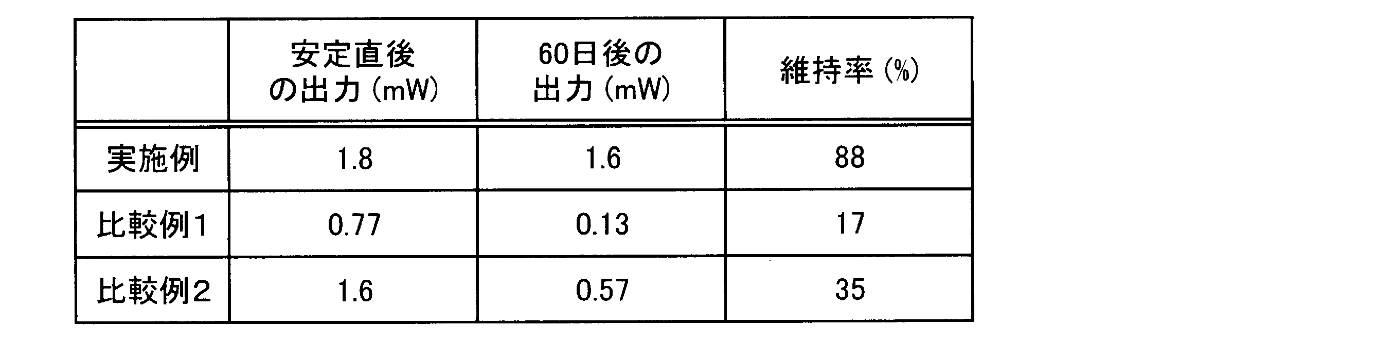
図5に示すように、実施例及び比較例ともに、微生物燃料電池の立ち上げには1週間程度を要し、両方とも徐々に出力が向上している。しかし、その後の出力維持には差異が発生した。
As shown in FIG. 5, in both the example and the comparative example, it takes about one week to start up the microbial fuel cell, and the output of both of them is gradually improved. However, there was a difference in the subsequent output maintenance.
つまり、比較例1の微生物燃料電池は、耐生分解性が低いウレタン樹脂からなる接着層を用いている。そのため、微生物燃料電池の運転に伴い、微生物が増殖して接着層を分解し、撥水層とガス拡散層に剥離が生じたと考えられる。剥離が生じた場合、撥水層とガス拡散層の間に電解液が入り、気相中の酸素の拡散速度が低下する。そのため、正極の特性が悪化し、微生物燃料電池の出力が低下すると考えられる。なお、この剥離は経時的に拡大するため、比較例1の微生物燃料電池は、60日運転後は安定直後よりも出力が低下し、出力維持率が悪化している。
That is, the microbial fuel cell of Comparative Example 1 uses an adhesive layer made of a urethane resin having low biodegradability. Therefore, it is considered that with the operation of the microbial fuel cell, microorganisms proliferated and decomposed the adhesive layer, and separation occurred between the water-repellent layer and the gas diffusion layer. When peeling occurs, an electrolytic solution enters between the water repellent layer and the gas diffusion layer, and the diffusion rate of oxygen in the gas phase decreases. Therefore, it is considered that the characteristics of the positive electrode deteriorate and the output of the microbial fuel cell decreases. In addition, since this peeling expands with time, the output of the microbial fuel cell of Comparative Example 1 is lower than that immediately after stabilization after 60 days of operation, and the output maintenance rate is deteriorated.
比較例2の微生物燃料電池は、耐アルカリ性が低いシリコーン樹脂からなる接着層を用いている。ここで、正極の近傍では、酸素還元反応に伴うプロトンの消費、すなわちpHの上昇が生じる。その結果、正極の接着層がアルカリ環境に晒されるため、撥水層とガス拡散層に剥離が生じたと考えられる。そして、この剥離は経時的に拡大するため、比較例2の微生物燃料電池は、60日運転後は安定直後よりも出力が低下し、出力維持率が悪化している。
The microbial fuel cell of Comparative Example 2 uses an adhesive layer made of a silicone resin having low alkali resistance. Here, in the vicinity of the positive electrode, proton consumption accompanying the oxygen reduction reaction, that is, an increase in pH occurs. As a result, the adhesive layer of the positive electrode is exposed to an alkaline environment, so that it is considered that peeling occurred between the water repellent layer and the gas diffusion layer. And since this peeling expands with time, the output of the microbial fuel cell of Comparative Example 2 is lower than that immediately after stabilization after 60 days of operation, and the output maintenance rate is deteriorated.
これに対し、実施例の微生物燃料電池は、耐生分解性及び耐アルカリ性が高いアクリル樹脂を用いている。そのため、比較例1及び2で生じた撥水層とガス拡散層との剥離を抑制して、高い出力を保持したと考えられる。
On the other hand, the microbial fuel cell of the example uses an acrylic resin having high biodegradability and alkali resistance. Therefore, it is considered that high output was maintained by suppressing the separation between the water repellent layer and the gas diffusion layer generated in Comparative Examples 1 and 2.
さらに、100日間運転した実施例及び比較例1の微生物燃料電池におけるガス拡散電極の外観を目視で観察した。その結果、実施例のガス拡散電極は、触媒層4のごく一部のみが膨れ上がり、剥離していた。これに対し、比較例1のガス拡散電極は、触媒層4の3~4割程度が膨れ上がり、剥離していた。このように、実施例のガス拡散電極では剥離が抑制されているため、撥水層1の内部へ電解液が侵入し難くなり、燃料電池の出力が高い状態に維持されていると考えられる。
Furthermore, the appearance of the gas diffusion electrode in the microbial fuel cell of Example and Comparative Example 1 operated for 100 days was visually observed. As a result, in the gas diffusion electrode of the example, only a part of the catalyst layer 4 was swollen and peeled off. On the other hand, in the gas diffusion electrode of Comparative Example 1, about 30 to 40% of the catalyst layer 4 was swollen and peeled off. As described above, in the gas diffusion electrode of the example, since peeling is suppressed, it is difficult for the electrolyte to enter the water-repellent layer 1 and the output of the fuel cell is maintained at a high level.
以上、本実施形態を説明したが、本実施形態はこれらに限定されるものではなく、本実施形態の要旨の範囲内で種々の変形が可能である。具体的には、図面において、撥水層1、接着層2、ガス拡散層3、触媒層4を備えたガス拡散電極10、並びに負極20、イオン透過膜30及び正極40は、矩形状に形成されている。しかし、これらの形状は特に限定されず、燃料電池の大きさ、並びに所望の発電性能等により任意に変更することができる。また、各層の面積も所望の機能が発揮できるならば任意に変更することができる。
Although the present embodiment has been described above, the present embodiment is not limited to these, and various modifications are possible within the scope of the gist of the present embodiment. Specifically, in the drawing, the gas diffusion electrode 10 provided with the water repellent layer 1, the adhesive layer 2, the gas diffusion layer 3, and the catalyst layer 4, and the negative electrode 20, the ion permeable membrane 30 and the positive electrode 40 are formed in a rectangular shape. Has been. However, these shapes are not particularly limited, and can be arbitrarily changed depending on the size of the fuel cell and the desired power generation performance. Further, the area of each layer can be arbitrarily changed as long as a desired function can be exhibited.
特願2016-000859号(出願日:2016年1月6日)の全内容は、ここに援用される。
The entire contents of Japanese Patent Application No. 2016-000859 (application date: January 6, 2016) are incorporated herein by reference.
本発明によれば、所定の接着層により撥水層とガス拡散層の接着性を高めるため、長期間に亘り撥水層からの漏水を抑制することができる。その結果、ガス拡散電極を用いた微生物燃料電池は、高出力を長期間維持することが可能となる。
According to the present invention, since the adhesion between the water repellent layer and the gas diffusion layer is enhanced by the predetermined adhesive layer, water leakage from the water repellent layer can be suppressed over a long period of time. As a result, the microbial fuel cell using the gas diffusion electrode can maintain a high output for a long time.
1 撥水層
2 接着層
3 ガス拡散層
4 触媒層
10 微生物燃料電池用ガス拡散電極
20 負極
30 イオン透過膜
40 正極
100 微生物燃料電池 DESCRIPTION OFSYMBOLS 1 Water repellent layer 2 Adhesive layer 3 Gas diffusion layer 4 Catalyst layer 10 Gas diffusion electrode for microbial fuel cells 20 Negative electrode 30 Ion permeable membrane 40 Positive electrode 100 Microbial fuel cell
2 接着層
3 ガス拡散層
4 触媒層
10 微生物燃料電池用ガス拡散電極
20 負極
30 イオン透過膜
40 正極
100 微生物燃料電池 DESCRIPTION OF
Claims (4)
- 織布又は不織布で形成され、撥水性を有する撥水層と、
前記撥水層の一方の面に積層された接着層と
前記接着層における撥水層側の面と反対側の面に積層されたガス拡散層と、
を備え、
前記接着層は、生分解性を有さず、かつ、耐アルカリ性を有する、微生物燃料電池用ガス拡散電極。 A water-repellent layer formed of woven or non-woven fabric and having water repellency;
An adhesive layer laminated on one surface of the water repellent layer, and a gas diffusion layer laminated on a surface opposite to the surface of the water repellent layer in the adhesive layer;
With
The gas diffusion electrode for a microbial fuel cell, wherein the adhesive layer does not have biodegradability and has alkali resistance. - 前記接着層は、ポリメチルメタクリレート、メタクリル酸-スチレン共重合体、スチレン-ブタジエンゴム、ブチルゴム、ニトリルゴム及びクロロプレンゴムからなる群より選ばれる少なくとも一つを含む樹脂からなる、請求項1に記載の微生物燃料電池用ガス拡散電極。 2. The adhesive layer according to claim 1, wherein the adhesive layer is made of a resin containing at least one selected from the group consisting of polymethyl methacrylate, methacrylic acid-styrene copolymer, styrene-butadiene rubber, butyl rubber, nitrile rubber, and chloroprene rubber. Gas diffusion electrode for microbial fuel cells.
- 前記ガス拡散層における接着層側の面と反対側の面に積層された触媒層をさらに備える、請求項1又は2に記載の微生物燃料電池用ガス拡散電極。 The gas diffusion electrode for a microbial fuel cell according to claim 1 or 2, further comprising a catalyst layer laminated on a surface opposite to the surface on the adhesive layer side in the gas diffusion layer.
- 微生物を担持する負極と、
水素イオンを透過するイオン透過膜と、
前記イオン透過膜を介して前記負極と隔てられた、請求項1乃至3のいずれか一項に記載の微生物燃料電池用ガス拡散電極からなる正極と、
を備える、微生物燃料電池。 A negative electrode carrying microorganisms;
An ion permeable membrane that transmits hydrogen ions;
A positive electrode comprising the gas diffusion electrode for a microbial fuel cell according to any one of claims 1 to 3, separated from the negative electrode through the ion permeable membrane,
A microbial fuel cell comprising:
Priority Applications (4)
| Application Number | Priority Date | Filing Date | Title |
|---|---|---|---|
| EP17735956.9A EP3401986A4 (en) | 2016-01-06 | 2017-01-05 | Gas diffusion electrode for microbial fuel cells and microbial fuel cell in which same is used |
| JP2017560389A JPWO2017119419A1 (en) | 2016-01-06 | 2017-01-05 | Gas diffusion electrode for microbial fuel cell, and microbial fuel cell using the same |
| US15/780,730 US20180358627A1 (en) | 2016-01-06 | 2017-01-05 | Gas diffusion electrode for microbial fuel cells and microbial fuel cell in which same is used |
| CN201780004333.3A CN108292756A (en) | 2016-01-06 | 2017-01-05 | Microbiological fuel cell gas-diffusion electrode and the microbiological fuel cell for using the gas-diffusion electrode |
Applications Claiming Priority (2)
| Application Number | Priority Date | Filing Date | Title |
|---|---|---|---|
| JP2016000859 | 2016-01-06 | ||
| JP2016-000859 | 2016-01-06 |
Publications (1)
| Publication Number | Publication Date |
|---|---|
| WO2017119419A1 true WO2017119419A1 (en) | 2017-07-13 |
Family
ID=59274372
Family Applications (1)
| Application Number | Title | Priority Date | Filing Date |
|---|---|---|---|
| PCT/JP2017/000062 WO2017119419A1 (en) | 2016-01-06 | 2017-01-05 | Gas diffusion electrode for microbial fuel cells and microbial fuel cell in which same is used |
Country Status (5)
| Country | Link |
|---|---|
| US (1) | US20180358627A1 (en) |
| EP (1) | EP3401986A4 (en) |
| JP (1) | JPWO2017119419A1 (en) |
| CN (1) | CN108292756A (en) |
| WO (1) | WO2017119419A1 (en) |
Cited By (1)
| Publication number | Priority date | Publication date | Assignee | Title |
|---|---|---|---|---|
| JP2019053906A (en) * | 2017-09-15 | 2019-04-04 | 学校法人立命館 | Electrode for power generation apparatus |
Families Citing this family (5)
| Publication number | Priority date | Publication date | Assignee | Title |
|---|---|---|---|---|
| WO2018209336A1 (en) * | 2017-05-12 | 2018-11-15 | Microrganic Technologies, Inc. | Microbial fuel cell cathode and method of making same |
| DE102019101483A1 (en) | 2019-01-22 | 2020-07-23 | Eisenhuth Gmbh & Co. Kg | Process and reactor for the electrochemical treatment of liquids, in particular organically contaminated wastewater |
| CN109830698B (en) * | 2019-02-18 | 2022-02-08 | 湖南农业大学 | Preparation method of electrode with hollow fold structure |
| CN113707924B (en) * | 2021-10-29 | 2022-03-22 | 中国科学院过程工程研究所 | Microbial fuel cell and construction method and application thereof |
| CN114335569B (en) * | 2021-12-22 | 2023-10-27 | 山东仁丰特种材料股份有限公司 | Gas diffusion layer for proton exchange membrane fuel cell and preparation method thereof |
Citations (4)
| Publication number | Priority date | Publication date | Assignee | Title |
|---|---|---|---|---|
| JP2011065821A (en) * | 2009-09-16 | 2011-03-31 | Kurita Water Ind Ltd | Microorganism power generation method and microorganism power generation device |
| JP2013145660A (en) * | 2012-01-13 | 2013-07-25 | Maezawa Kasei Ind Co Ltd | Microbial fuel cell |
| JP2015046361A (en) * | 2013-08-29 | 2015-03-12 | 株式会社日立製作所 | Cathode for microbial fuel battery use, method for manufacturing the same, and microbial fuel battery |
| WO2015198520A1 (en) * | 2014-06-24 | 2015-12-30 | パナソニック株式会社 | Gas diffusion electrode, electrochemical device, and fuel cell |
Family Cites Families (6)
| Publication number | Priority date | Publication date | Assignee | Title |
|---|---|---|---|---|
| US4338370A (en) * | 1980-04-07 | 1982-07-06 | Goodyear Aerospace Corporation | Chemically resistant coated fabric |
| WO2001054216A2 (en) * | 2000-01-18 | 2001-07-26 | Ramot University Authority For Applied Research And Industrial Development Ltd. | Fuel cell with proton conducting membrane |
| US7470483B2 (en) * | 2002-12-11 | 2008-12-30 | Panasonic Corporation | Electrolyte membrane-electrode assembly for fuel cell and operation method of fuel cell using the same |
| CN102918690B (en) * | 2010-06-29 | 2016-02-24 | 伟途股份有限公司 | Gas-diffusion electrode and production method, the assembly comprising it and production comprise the method for its membrane electrode assembly |
| AU2014228812A1 (en) * | 2013-03-15 | 2015-07-23 | Oregon State University | Microbial fuel cell and methods of use |
| CN107431214A (en) * | 2015-04-13 | 2017-12-01 | 松下电器产业株式会社 | Electrode assembly and microbiological fuel cell |
-
2017
- 2017-01-05 WO PCT/JP2017/000062 patent/WO2017119419A1/en unknown
- 2017-01-05 CN CN201780004333.3A patent/CN108292756A/en active Pending
- 2017-01-05 EP EP17735956.9A patent/EP3401986A4/en not_active Withdrawn
- 2017-01-05 US US15/780,730 patent/US20180358627A1/en not_active Abandoned
- 2017-01-05 JP JP2017560389A patent/JPWO2017119419A1/en not_active Ceased
Patent Citations (4)
| Publication number | Priority date | Publication date | Assignee | Title |
|---|---|---|---|---|
| JP2011065821A (en) * | 2009-09-16 | 2011-03-31 | Kurita Water Ind Ltd | Microorganism power generation method and microorganism power generation device |
| JP2013145660A (en) * | 2012-01-13 | 2013-07-25 | Maezawa Kasei Ind Co Ltd | Microbial fuel cell |
| JP2015046361A (en) * | 2013-08-29 | 2015-03-12 | 株式会社日立製作所 | Cathode for microbial fuel battery use, method for manufacturing the same, and microbial fuel battery |
| WO2015198520A1 (en) * | 2014-06-24 | 2015-12-30 | パナソニック株式会社 | Gas diffusion electrode, electrochemical device, and fuel cell |
Non-Patent Citations (1)
| Title |
|---|
| See also references of EP3401986A4 * |
Cited By (2)
| Publication number | Priority date | Publication date | Assignee | Title |
|---|---|---|---|---|
| JP2019053906A (en) * | 2017-09-15 | 2019-04-04 | 学校法人立命館 | Electrode for power generation apparatus |
| JP7043052B2 (en) | 2017-09-15 | 2022-03-29 | 学校法人立命館 | Electrodes for power generation equipment and power generation equipment |
Also Published As
| Publication number | Publication date |
|---|---|
| JPWO2017119419A1 (en) | 2018-09-27 |
| US20180358627A1 (en) | 2018-12-13 |
| EP3401986A4 (en) | 2019-01-02 |
| EP3401986A1 (en) | 2018-11-14 |
| CN108292756A (en) | 2018-07-17 |
Similar Documents
| Publication | Publication Date | Title |
|---|---|---|
| WO2017119419A1 (en) | Gas diffusion electrode for microbial fuel cells and microbial fuel cell in which same is used | |
| JP6368036B2 (en) | Electrode structure and microbial fuel cell | |
| JP6364529B2 (en) | Electrode manufacturing method and electrode | |
| JP6438115B2 (en) | Microbial fuel cell system | |
| US20200317543A1 (en) | Purification unit and purification device | |
| JP6643642B2 (en) | Purification unit and purification device | |
| US20210280888A1 (en) | Microbial fuel cell | |
| WO2016114139A1 (en) | Microbial fuel cell system | |
| WO2017175260A1 (en) | Electrode, fuel cell and water treatment device | |
| JP2020087804A (en) | Microbial fuel cell and liquid processing unit | |
| JP6703859B2 (en) | Microbial fuel cell | |
| JP6660174B2 (en) | Method for producing electrode and method for producing membrane electrode assembly | |
| WO2017199475A1 (en) | Liquid processing unit and liquid processing device | |
| JP2017228411A (en) | Electrode composite and fuel cell | |
| JP2019076833A (en) | Liquid treatment system | |
| WO2018203455A1 (en) | Liquid treatment system | |
| JP2017228410A (en) | Electrode and microbial fuel cell | |
| WO2017195406A1 (en) | Microbial fuel cell and liquid treatment unit using same | |
| WO2019078003A1 (en) | Microbial fuel cell, liquid processing system, and liquid processing structure | |
| JP2017117586A (en) | Method of manufacturing electrode composite | |
| WO2019078002A1 (en) | Liquid processing system | |
| JP2020099853A (en) | Liquid treatment system | |
| JP2020099854A (en) | Liquid treatment system | |
| JP2020099851A (en) | Liquid treatment system | |
| JP2020099850A (en) | Liquid treatment system |
Legal Events
| Date | Code | Title | Description |
|---|---|---|---|
| 121 | Ep: the epo has been informed by wipo that ep was designated in this application |
Ref document number: 17735956 Country of ref document: EP Kind code of ref document: A1 |
|
| ENP | Entry into the national phase |
Ref document number: 2017560389 Country of ref document: JP Kind code of ref document: A |
|
| NENP | Non-entry into the national phase |
Ref country code: DE |