US20120320339A1 - Ophthalmologic apparatus, ophthalmologic system, controlling method for ophthalmologic apparatus, and program for the controlling method - Google Patents
Ophthalmologic apparatus, ophthalmologic system, controlling method for ophthalmologic apparatus, and program for the controlling method Download PDFInfo
- Publication number
- US20120320339A1 US20120320339A1 US13/488,735 US201213488735A US2012320339A1 US 20120320339 A1 US20120320339 A1 US 20120320339A1 US 201213488735 A US201213488735 A US 201213488735A US 2012320339 A1 US2012320339 A1 US 2012320339A1
- Authority
- US
- United States
- Prior art keywords
- image
- acquired
- eye
- working distance
- tomographic image
- Prior art date
- Legal status (The legal status is an assumption and is not a legal conclusion. Google has not performed a legal analysis and makes no representation as to the accuracy of the status listed.)
- Abandoned
Links
Images


Classifications
-
- A—HUMAN NECESSITIES
- A61—MEDICAL OR VETERINARY SCIENCE; HYGIENE
- A61B—DIAGNOSIS; SURGERY; IDENTIFICATION
- A61B3/00—Apparatus for testing the eyes; Instruments for examining the eyes
- A61B3/10—Objective types, i.e. instruments for examining the eyes independent of the patients' perceptions or reactions
- A61B3/102—Objective types, i.e. instruments for examining the eyes independent of the patients' perceptions or reactions for optical coherence tomography [OCT]
Definitions
- the present invention relates to an ophthalmologic apparatus, an ophthalmologic system, a controlling method for an ophthalmologic apparatus, and a program for the controlling method.
- the present invention relates to an image processing apparatus and an image processing method which are suitable for those ophthalmologic apparatuses used in ophthalmological diagnosis and treatment.
- An optical tomographic imaging apparatus (or optical coherence tomography (OCT) apparatus) that acquires a fundus tomographic image by utilizing optical interference enables three-dimensional observation of the state of an internal structure of a retinal fundus, and hence the OCT apparatus is useful for performing diagnosis of the diseases.
- the retinal fundus has a multiple layer structure, and it is known that a thickness of each layer can be used as an index indicating development of the disease.
- the OCT apparatus has enabled quantitative observation of the layer structure of the retinal fundus, and hence it is expected that the development of the disease can be grasped more precisely.
- FIG. 3 is a schematic view of a tomographic image of a macula lutea and its vicinity of a myopic eye fundus.
- FIG. 3 illustrates boundaries L 1 to L 4 of a layer structure of a retina.
- the boundary L 1 is a boundary between an internal limiting membrane and its upper organism (hereinafter, referred to as ILM)
- the boundary L 2 is a boundary between a nerve fiber layer and its lower layer (hereinafter, referred to as NFL)
- the boundary L 3 is a boundary between a photoreceptor inner/outer segment junction and its upper layer (hereinafter, referred to as IS/OS)
- the boundary L 4 is a boundary between a retinal pigment epithelium and its lower organism (hereinafter, referred to as RPE).
- a thickness of the retina layer is generally smaller than the actual thickness thereof in a tomographic image of a fundus having a large curvature due to myopia or the like.
- a distance from an objective lens of the OCT apparatus to an eye whose image is to be acquired is called a working distance (WD).
- This distance is designated to a value optimal for the apparatus, and an operation method is determined so that a focal point obtained by using an anterior eye part becomes substantially close to this optimal value.
- the image may be often acquired at a point shifted from the optimal value in order that the retina layers are placed within one tomographic image.
- US 2007/0076217 discloses measurement of an axial length of an eye to be inspected based on a tomographic image of an anterior eye part and a tomographic image of a fundus of the eye to be inspected, which are obtained by two OCT apparatuses.
- the present invention provides an ophthalmologic apparatus, including: an image acquiring unit configured to acquire a tomographic image of a fundus of an eye to be inspected; a calculating unit configured to calculate a working distance, based on a predetermined layer of the tomographic image, a coherence gate position, and an axial length of the eye to be inspected, at a time when the tomographic image is acquired; and a correcting unit configured to correct the tomographic image based on the working distance.
- a curvature of a retina can be corrected based on information obtained by analyzing a tomographic image.
- FIG. 1 is a diagram illustrating a functional configuration of an image processing apparatus according to a first embodiment of the present invention.
- FIGS. 2A and 2B are flowcharts illustrating a process procedure of the image processing apparatus according to the first embodiment of the present invention.
- FIG. 3 is a schematic view of a retina tomographic image having a large curvature.
- FIG. 4 is a diagram illustrating an OCT apparatus.
- FIG. 5A is a diagram illustrating a positional relationship among a WD, an eyeball, and a retina in an acquired image.
- FIG. 5B is a schematic diagram illustrating an outline of ray tracing for determining a rotation center.
- FIG. 5C is a schematic diagram illustrating coordinate conversion.
- FIG. 6A shows a variation of curvature on an image due to a variation of working distance in a model eye.
- FIG. 6B shows an example of curvature correction by the process according to the first embodiment of the present invention.
- FIG. 7A shows an image obtained by superimposing the images shown in FIG. 6A .
- FIG. 7B shows an image obtained by superimposing the images shown in FIG. 6B .
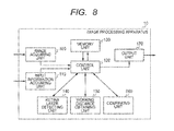
- FIG. 8 is a diagram illustrating a functional configuration of the image processing apparatus according to a second embodiment of the present invention.
- FIG. 9 is a flowchart illustrating a process procedure of the image processing apparatus according to the second embodiment of the present invention.
- FIG. 10 is a table showing a model of refraction elements of an eye to be inspected.
- FIG. 11 is a graph showing an example of a relationship between the working distance and a distance from the rotation center to the retina.
- FIG. 12 is a diagram illustrating a functional configuration of the image processing apparatus according to a third embodiment of the present invention.
- FIG. 13 is a flowchart illustrating a process procedure of the image processing apparatus according to the third embodiment of the present invention.
- variation of curvature of retina of the acquired tomographic image is corrected by using a working distance (WD) obtained when the image is acquired so that a correct curvature is measured. More specifically, an axial length of an eye to be inspected is obtained, the WD is calculated from a coherence gate position when the image is acquired and a retina position in an acquired tomographic image, and the acquired tomographic image is corrected based on this WD value. With this correction, a correct curvature can be measured, and comparison among eyes to be inspected or evaluation of the variation with time can be performed.
- WD working distance
- a distance from a reference point to an objective lens is obtained, and the axial length of the eye to be inspected, the coherence gate position when the image is acquired, and the retina position of the acquired tomographic image are obtained.
- the WD is calculated, and hence the curvature is corrected.
- FIG. 1 is a diagram illustrating a functional configuration of an image processing apparatus 10 according to this embodiment.
- an image acquiring unit 100 corresponds to an image acquiring unit of the present invention, which acquires a tomographic image acquired by an optical tomographic imaging apparatus (OCT apparatus) or a tomographic image stored in an external database directly or via a network or the like.
- An input information acquiring unit 110 acquires, from the OCT apparatus or the database, information of the axial length of the eye to be inspected and the coherence gate position when the image is acquired.
- the acquired information is stored in a memory unit 130 via a control unit 120 .
- the image acquiring unit 100 further includes a retina layer detecting unit 140 , a working distance obtaining unit 150 , and an image correcting unit 160 . Based on the obtained working distance, the entire image is corrected so that curvature of a detected layer in the acquired tomographic image is corrected, and a result of the correction is stored in the memory unit 130 .
- An output unit 170 outputs the corrected tomographic image to a monitor or the like, and saves the process result stored in the memory unit 130 in the database.
- FIG. 4 is a diagram illustrating a configuration of the optical tomographic imaging apparatus used in this embodiment.
- the optical tomographic imaging apparatus is constituted of a Michelson interferometer. Emerging light 102 from a light source 101 is guided to a single mode fiber 107 to enter an optical coupler 108 .
- the optical coupler 108 split the light into reference light 103 and measuring light 104 . Then, the measuring light 104 is reflected or scattered by a measurement point of a retina 125 to be observed and becomes return light 105 to travel back to the optical coupler 108 . Then, the optical coupler 108 combines the return light 105 with the reference light 103 that has propagated through a reference light path, so as to emit combined light 106 , which then reaches a spectroscope 119 .
- the light source 101 is a super luminescent diode (SLD), which is a typical low coherence light source.
- SLD super luminescent diode
- the wavelength near infrared light is suitable in view of measuring an eye. Further, the wavelength affects a lateral resolution of the acquired tomographic image, and hence the wavelength is desirable to be as short as possible.
- a center wavelength is set to 840 nm, and a wavelength width is set to 50 nm. It is to be understood that another wavelength may be selected depending on a measurement part to be observed.
- an SLD is selected in this embodiment, but any type of light source may be selected as long as the light source can emit low coherent light, and an amplified spontaneous emission (ASE) light source or the like may also be used.
- ASE amplified spontaneous emission
- the reference light path of the reference light 103 is described.
- the reference light 103 split by the optical coupler 108 is converted into substantially parallel light by a lens 109 - 1 , and is then emitted.
- the reference light 103 passes through a dispersion compensation glass 310 , and the direction of the reference light 103 is changed by a mirror 111 .
- the reference light 103 is guided to the spectroscope 119 again via the optical coupler 108 .
- the dispersion compensating glass 310 compensates for dispersion of the measuring light 104 propagating forward and backward between an eye to be inspected 124 and a scanning optical system with respect to the reference light 103 .
- an optical path length of the reference light can be adjusted by moving the mirror 111 in the arrow direction by an electric stage 112 so that the coherence gate position corresponding to this optical path length can be adjusted.
- the coherence gate means a position in the measuring light path which matches the reference light path in terms of the distance.
- the electric stage 112 is controlled by the control unit 120 , and the control unit 120 stores position information of the electric stage 112 when the image is acquired and the acquired tomographic image associated with each other.
- the measuring light path of the measuring light 104 is described.
- the measuring light 104 split by the optical coupler 108 is converted into substantially parallel light by the lens 109 - 2 , and is then emitted.
- the resultant light is input to a mirror of an XY scanner 113 constituting the scanning optical system.
- FIG. 4 illustrates the XY scanner 113 as one mirror, but in reality, two mirrors are disposed closely to each other, which include an X-scan mirror and a Y-scan mirror.
- the measuring light passes through a lens 114 and an objective lens 128 to reach the eye to be inspected 124 .
- the measuring light 104 that has reached the eye to be inspected 124 is reflected by the retina 125 and the like to be the reflected light 105 , which propagates backward through the path of the measuring light 104 and enters the optical coupler 108 , so as to be combined with the reference light 103 .
- the combined light 106 generated by the optical coupler 108 is split into beams having individual wavelengths by the spectroscope 119 , and intensities of the respective beams are detected and output to a computer 320 .
- the computer 320 performs a process of Fourier transform or the like so as to generate a tomographic image.
- the memory unit of the computer 320 stores design values of the OCT apparatus, which can be output externally.
- a WD 126 is defined as a distance from a surface of a cornea 122 to a surface of the objective lens 128 .
- a value of the WD 126 is designed so that a pupil 129 of the eye becomes a rotation center when the measuring light 104 scans the retina 125 . Therefore, it is desirable to adjust the WD 126 to be a design value so as to acquire the tomographic image.
- the OCT optical system has a small NA and therefore a large focal depth. As a result, even if the WD is shifted from the design value, the image can be acquired. Note that, if the WD is shifted largely from the design value, light may be blocked by an iris 127 , or the image may be defocused.
- the image processing apparatus 10 of FIG. 1 may acquire the tomographic image directly from the computer 320 of the optical tomographic imaging apparatus of FIG. 4 , or may acquire the tomographic image via a network.
- the tomographic image acquired by the optical tomographic imaging apparatus and the information of the eye to be inspected are stored in the database connected via network, and the image processing apparatus 10 acquires the tomographic image and the information of the eye to be inspected from the database.
- Step S 210 the input information acquiring unit 110 acquires information about the OCT apparatus, for example, a reference distance 155 that is a distance from a reference position 121 to the objective lens 128 , which is illustrated in FIG. 5A , from the computer 320 and stores the information in the memory unit 130 via the control unit 120 .
- a reference position 121 of acquiring the image is now described in more detail.
- the reference position 121 of acquiring the image in this embodiment is a coherence gate position when the mirror 111 moves to the origin (a position within a moving range of the mirror 111 at which the reference light path length becomes shortest).
- the distance 155 from the reference position 121 to the objective lens is fixed and set to be always a determined value. In FIG.
- the reference position 121 is illustrated on the opposite side to the eyeball when viewed from the objective lens 128 for easy understanding, but in reality, the reference position 121 exists on the same side as the eyeball when viewed from the objective lens 128 . This is because that it is sufficient if the moving range of the mirror 111 is set so that the coherence gate position covers an assumed range of the object to be measured. Therefore, if the positional relationship is defined as illustrated in FIG. 5A , the reference distance 155 becomes a negative value.
- the reference position 121 is not limited to the position obtained in the above-mentioned case, but may be a position obtained in a case where the mirror 111 is placed in an arbitrary position.
- the reference position 121 is adjusted so that the origin is a mirror position when the reference light path length becomes a certain value, and hence the constant reference distance 155 can be set without depending on the apparatus.
- the input information acquiring unit 110 as an eye information acquiring unit in the present invention acquires information of the eye to be inspected from the database or an input by an operator using an input unit (not shown).
- information of the eye to be inspected refers to eye parameters typified by an axial length, which are characteristics unique to the eye to be inspected.
- the acquired information is stored in the memory unit 130 via the control unit 120 .
- the eye information acquiring unit acquires eye parameters such as a distance from the reference position 121 to the coherence gate position, the axial length of the eye to be inspected, and the like. Note that, the light beam is refracted and propagates inside the eye to be inspected as a property of light.
- the anterior eye part such as the cornea and a crystalline lens
- the above-mentioned property of light can be taken into account, and hence an accuracy of correcting the tomographic image can be improved.
- Step S 230 the image acquiring unit 100 acquires the tomographic image to be analyzed from the optical tomographic imaging apparatus of FIG. 4 connected to the image processing apparatus 10 , or the database storing the tomographic image acquired by the optical tomographic imaging apparatus.
- the acquired tomographic image is stored in the memory unit 130 via the control unit 120 .
- the coherence gate position 126 may be described in an image acquiring information file attached to the tomographic image, or may be included as tag information of the image.
- the reference position 121 is the coherence gate position when the mirror 111 is at the origin, and hence when the moving distance from the origin of the coherence gate is converted into an actual distance length based on a value of the coherence gate position 126 when the image is acquired, and a distance 153 is obtained as illustrated in FIG. 5A .
- the retina layer detecting unit 140 detects a retina layer boundary from the tomographic image stored in the memory unit 130 .
- the retina layer detecting unit 140 functions as a layer extracting unit in the present invention, which extracts a predetermined layer from the tomographic image.
- the retina position for measuring the axial length is generally the ILM, and hence detection of the RPE having higher luminance than the ILM is described in this embodiment, but other layer boundaries can also be detected by the same method.
- the retina layer detecting unit 140 performs a smoothing filter process on the tomographic image so as to remove noise components. Then, an edge detection filter process is performed so that an edge component is detected from the tomographic image, and then an edge corresponding to a boundary between layers is extracted. Further, a background region is specified from the tomographic image on which the edge detection has been performed, and a luminance value characteristic of the background region is extracted from the tomographic image. Then, a peak value of the edge component and the luminance value characteristic between the peaks are used so that the boundary between the layers is determined.
- the retina layer detecting unit 140 searches for an edge from a corpus vitreum side in a depth direction of the fundus, and a boundary between the corpus vitreum and the retina layer (ILM) is determined from a peak of the edge component, luminance characteristics of the upper and lower parts thereof, and a luminance characteristic of the background region. Further, an edge is searched for in the depth direction of the fundus, and a retina pigment epithelium (RPE) layer boundary is determined by referring to the peak of the edge component, the luminance characteristic between the peaks, and a luminance characteristic of the background region.
- RPE retina pigment epithelium
- the ILM boundary (control point) detected in this way is sent to the control unit 120 and is stored in the memory unit 130 .
- a height (y coordinate) of an ILM boundary position 302 in a center 301 of the acquired image is converted into an actual distance by using a pixel resolution and a refractive index and is stored in the memory unit 130 via the control unit 120 .
- Step S 250 the working distance obtaining unit 150 acquires the reference distance 155 , an axial length 152 , and the coherence gate distance 153 acquired in Steps S 210 to S 230 from the memory unit 130 .
- the working distance obtaining unit 150 functions as a calculating unit in the present invention that calculates the working distance as a distance to the eye to be inspected when the tomographic image is acquired based on a distance to the coherence gate position, an axial length of the eye to be inspected, and a retina distance.
- the control point of the retina position detected in Step S 240 is acquired from the memory unit 130 , and an image retina distance 154 to the retina position in the image is calculated.
- the calculation of the image retina distance 154 from the coherence gate when the image is acquired to the extracted layer is performed in the unit defined as the obtaining unit in the above-mentioned configuration. Specifically, as illustrated in FIG. 3 , the ILM position 302 at the image center 301 is acquired, and a z coordinate thereof is determined so that the number of pixels from the upper limit of the image to the retina position is obtained. Based on the pixel resolution of the image and the refractive index of the corpus vitreum, the actual distance length is obtained by conversion, and hence the image retina distance 154 of FIG. 5A is acquired.
- FIG. 5A illustrates a positional relationship among those distances. That is, the following equation is satisfied.
- the image is generated so that the upper limit part of the image becomes the coherence gate 126 . If there is a difference ⁇ L between the upper limit part of the image and the coherence gate position, a value obtained by subtracting the difference ⁇ L from the reference distance 155 is set as a new reference distance, so as to perform the same calculation. From Equation 1, the working distance 151 can be acquired.
- the working distance 151 acquired in this way is stored in the memory unit 130 via the control unit 120 .
- Step S 260 the image correcting unit 160 corrects the acquired image based on the working distance acquired in Step S 250 .
- the process in Step S 260 is divided into three parts as illustrated in FIG. 2B , which are calculation of the rotation center in Step S 261 , conversion into a spatial image in Step S 262 , and generation of a corrected image in Step S 263 . Individual steps are described in detail as follows.
- Step S 261 the image correcting unit 160 performs calculation of the rotation center based on the working distance acquired in Step S 250 .
- the image correcting unit 160 corresponds to a correcting unit in the present invention, which corrects the tomographic image based on the determined working distance.
- FIG. 5B is a schematic diagram illustrating an outline of ray tracing for determining the rotation center.
- FIG. 5B illustrates a cornea E 1 , an anterior chamber E 2 , a crystalline lens E 3 , and a corpus vitreum E 4 .
- FIG. 5B further illustrates a rotation center 209 viewed from the objective lens and an effective rotation center 202 viewed from the retina. All rays entering at an angle of ⁇ 0 from the rotation center 209 are refracted by a cornea surface, a boundary between the cornea and the anterior chamber, a boundary between the anterior chamber and the crystalline lens, and a boundary between the crystalline lens and the corpus vitreum, which are approximated by spheres, and enter the retina.
- the rays entering from the rotation center 209 look as if the rays enter from the effective rotation center 202 when viewed from the retina.
- Parameters including a curvature radius, a thickness, and a refractive index are assigned to each of the cornea, the anterior chamber, the crystalline lens, and the corpus vitreum. Average parameter values of human eyes are shown in FIG. 10 . In addition, as parameters of the model eye, values designed for each model eye are used.
- the ray tracing is performed as follows. First, rays entering from a pivot position at an angle of ⁇ 0 are expressed by the following equation, supposing that the pivot position is the origin.
- the cornea surface is expressed by the following equation, supposing that an x value of a point where the cornea surface crosses an x axis is denoted by L 1 , and a curvature radius of the cornea surface is denoted by R 1 .
- An intersection point (x 1 , y 1 ) where the incident light crosses the cornea surface is determined by Equations 1 and 2.
- the angle ⁇ 1 is determined as follows.
- refraction at the cornea surface is expressed as follows by Snell's law, supposing that an angle between a ray after the refraction and the direction perpendicular to the cornea surface is denoted by ⁇ 1 .
- Equation 4 n denotes a refractive index of each medium, and it is supposed that a refractive index n 0 in the air is 1 (one).
- the ray refracted at the cornea surface is expressed as a line that passes the intersection point (x 1 , y 1 ) and has a gradient of tan( ⁇ 1 ⁇ 1 ).
- the boundary between the cornea and the anterior chamber is expressed by the following equations, supposing that an x value of the point where the boundary between the cornea and the anterior chamber crosses the x axis is denoted by L 2 , and the curvature radius of the boundary is denoted by R 2 , similarly to the case of Equation 2.
- an intersection point (x 2 , y 2 ) of the incident light with the boundary between the cornea and the anterior chamber is determined from Equations 5 and 6. Supposing that an angle between the incident ray and a direction perpendicular to the boundary between the cornea and the anterior chamber at the intersection point is ⁇ 1 ⁇ 1 + ⁇ 2 , the angle ⁇ 2 is determined as follows.
- refraction at the boundary between the cornea and the anterior chamber is expressed as follows, supposing that an angle between the ray after the refraction and the direction perpendicular to the boundary between the cornea and the anterior chamber is denoted by ⁇ 2 .
- each solution of Equations 1, 2, 5, and 6 is an intersection point of a circle and a line, which include two points. An appropriate one of the points is selected considering a shape of the eyeball.
- the ray entering the retina is expressed as follows as a line that passes an intersection point (x 4 , y 4 ) at the boundary between the crystalline lens and the corpus vitreum and has a gradient of tan( ⁇ 4 ⁇ 4 ).
- a positional relationship between a variation of the working distance and the effective rotation center 202 is described.
- a distance from the rotation center 202 to the retina 125 is not proportional to the variation of the working distance. This is because the light is refracted at the cornea and at the crystalline lens.
- a horizontal axis indicates the variation of the working distance from the pupil
- a vertical axis indicates the distance from the rotation center 202 to the retina 125 .
- Step S 262 the image correcting unit 160 performs conversion of the acquired image into a spatial image based on the rotation center calculated in Step S 261 .
- FIG. 5C is a schematic diagram illustrating the coordinate conversion.
- the tomographic image is acquired by the OCT apparatus by generating a rectangular image from a signal acquired in a sector region from the coherence gate position 126 like concentric circles, with the effective pivot position 202 as the center ( FIG. 5C ).
- the effective pivot position 202 is regarded as the origin of coordinates, a retina direction is regarded as a z axis, and a direction corresponding to a scan angle is regarded as an x axis.
- the upper left corner is regarded as the origin
- the number of pixels from the origin in a depth direction of the retina is denoted by j
- the number of pixels from the origin in a direction parallel to the retina is denoted by i.
- a size of the image is N h in the depth direction and N w in the width direction.
- a scan angle viewed from the retina is denoted by ⁇ .
- Positions on the j-th row in the image are positions having the same distance from the coherence gate, and hence the following relationships are satisfied.
- Equation 11 L denotes an actual distance from the effective pivot position to the coherence gate position, h denotes a pixel resolution in the retina depth direction, and n denotes a refractive index.
- the upper end of the image is the coherence gate position.
- Step S 263 the image correcting unit 160 forms the corrected image based on the conversion into the spatial image in Step S 262 . Then, the formed corrected image is stored in the memory unit 130 via the control unit 120 .
- the corrected image is formed by reflecting the actual position of the region in which the tomographic image is acquired.
- the region becomes a sector. Therefore, the region is expanded so that the region in which the tomographic image is acquired is substantially included, and the image is formed.
- the resolution of the OCT tomographic image is different between the direction parallel to the retina (horizontal direction in the image) and the depth direction of the retina (vertical direction in the image). This difference is provided for the purpose of acquiring more information in the depth direction of the retina, and therefore the image is enlarged for display in the vertical direction.
- this aspect ratio is maintained and saved. This is because the detailed information in the depth direction of the retina is important for medical doctors.
- the space coordinates of the center of the tomographic image are set to (0, z center ).
- the pixel on the tomographic image corresponding to the space coordinates (x, z) is expressed as follows as reverse conversions of Equations 13 and 14.
- Values of (i, j) determined by Equations 18 and 19 are real values.
- the real values are rounded down or up to be integers, and linear interpolation of four pixels on the tomographic image is performed to calculate pixel values of the pixel (m, l) on the corrected image.
- Step S 270 the output unit 170 displays the corrected image generated in Step S 260 on the monitor via the output unit 170 .
- FIGS. 6A and 6B show an example of the acquired tomographic image and the corrected image thereof.
- FIG. 6A shows tomographic images of the same model eye acquired while changing the working distance. The working distance is largest in the image having the number 01 , and the working distance becomes smaller (push amount becomes larger) as the number increases. As shown in FIG. 6A , it is understood that the curvature on the image varies as the working distance varies.
- Step S 280 the output unit 170 stores the information of the eye to be inspected and the working distance calculated based on the information, which are acquired in Steps S 210 to Step S 250 , in the database.
- the OCT apparatus when the image of the retina is acquired by the OCT apparatus, it is possible to display the image after correcting the difference of curvature due to the difference of working distance when the image is acquired, and thus there is an effect that the difference of curvature among different eyes to be inspected and a variation of the curvature in the same eye to be inspected can be compared in a quantitative manner.
- the acquired working distance is compared with the working distance of the image that has been acquired before for the same eye to be inspected, and a difference between the working distances is displayed so as to assist the operator to acquire an image at the same working distance.
- the first embodiment describes that it is possible to correct the image to have the same curvature even if the images are acquired at different working distances.
- image quality of the corrected image is deteriorated from that of the original tomographic image. Therefore, if the image is acquired at a working distance as close as possible to the working distance when the image was acquired last time, it is possible to compare the retina state between images without correction.
- FIG. 8 A functional configuration of the image processing apparatus 10 according to this embodiment is illustrated in FIG. 8 .
- the comparing unit 860 compares the working distance calculated from the acquired tomographic image with the working distance when the image was acquired last time.
- the working distance when the image was acquired last time is regarded as a reference working distance to be a reference for the working distance of acquiring the image this time.
- the reference working distance may remain the same as the working distance when the image was acquired last time or may be set based on the working distance of the last time, for example, by multiplying the working distance of the last time by a predetermined coefficient.
- the working distance in which the distance from the rotation center to the retina remains the same as that of the last time the image is acquired may be regarded as the reference working distance.
- Step S 210 , S 220 , S 240 , and S 250 is the same as that described in the first embodiment, and hence description thereof is omitted.
- the process procedure of Steps S 210 to S 250 is the same as that described in the first embodiment, but the tomographic image acquired in Step S 930 in this embodiment is different from that in the first embodiment.
- the tomographic image acquired in Step S 930 of this embodiment is a prescan image before acquiring the image while the tomographic image acquired in Step S 930 of the first embodiment is the acquired tomographic image.
- the prescan image refers to an image acquired at high speed by rough sampling, which is displayed to the operator for performing adjustment of the coherence gate position or the focus.
- the tomographic image acquired regularly is referred to as a regular scan image.
- the working distance of the acquired prescan image is calculated and displayed in real time.
- Step S 925 the input information acquiring unit 110 acquires the working distance when the image was acquired last time for the same eye to be inspected from the database based on the information of the eye to be inspected stored in the memory unit 130 . Then, the acquired working distance is stored in the memory unit 130 via the control unit 120 .
- Step S 930 the image acquiring unit 100 acquires the tomographic image from the OCT apparatus connected to the image processing apparatus 10 . Then, the acquired tomographic image is stored in the memory unit 130 via the control unit 120 .
- the coherence gate position 126 when the acquired image is acquired, and information as to whether the acquired tomographic image is acquired as the prescan image or as the regular scan image is acquired and stored in the memory unit 130 via the control unit 120 .
- Step S 960 the comparing unit 860 compares the working distance when the image was acquired last time, which is acquired in Step S 925 , with the working distance when the prescan image is acquired, which is acquired in Step S 250 , and a difference between the working distances is calculated. Then, the calculated difference is displayed on the monitor (not shown) via the output unit 170 .
- a difference value on the display screen of the prescan image as a positive value if the working distance is larger than that when the image was acquired last time, or as a negative value if the working distance is smaller than that when the image was acquired last time.
- the difference value may be displayed in blue, and if the difference value is out of the range, the difference value may be displayed in red or in a larger size, so as to warn the operator effectively.
- Step S 970 the control unit 120 branches the process based on information whether or not the acquired image acquired in Step S 930 is the prescan image.
- the process returns back to Step S 930 in which a next image is acquired and the same process is repeated.
- the process proceeds to Step S 980 .
- Step S 980 the output unit 170 stores the information of the eye to be inspected and the working distance calculated based on the information, which are acquired in Steps S 210 to S 960 , in the database.
- a result of acquiring the image of the eye to be inspected performed by using the reference working distance is displayed on a display unit, and further a display form indicating that the assistance to acquire the image has been performed using the reference working distance is displayed together.
- the operation of causing the display unit to display a display form in which the assistance to acquire the image of the eye to be inspected is being performed at the reference working distance which is set based on the working distance is performed by a unit functioning as a display control unit in the control unit 120 in the present invention.
- a third embodiment of the present invention has a feature that in order to note a structure of the retina in the macula lutea and its vicinity, the rotation center is adjusted so that the distance from the macula lutea is equalized in the acquired image having the macula lutea as its center.
- the information of how much the working distance of the current prescan image is shifted from the reference of the working distance in which the distance from the macula lutea is equal to that when the image was acquired last time is provided to the operator, and hence the operator is assisted in adjusting the working distance.
- FIG. 12 A functional configuration of the image processing apparatus 10 according to this embodiment is illustrated in FIG. 12 .
- portions other than a rotation center calculating portion 1260 of FIG. 12 are the same as those illustrated in FIG. 1 , and hence descriptions thereof are omitted.
- the rotation center calculating portion 1260 calculates a distance between the rotation center and the retina based on the working distance calculated from the acquired tomographic image. This corresponds to an operation of Step S 261 in the first embodiment. Then, a difference between the working distance in a case where the distance from the rotation center to the retina is the same as that when the image was acquired last time and the working distance in a target image are determined.
- the rotation center is calculated in real time from the acquired prescan image, and the display based on the value is performed.
- a distance between the rotation center and the retina is calculated from the calculated value of the rotation center, and a display is performed so as to prompt the operator to adjust the working distance so that the distance between the rotation center and the retina becomes the same as that when the image was acquired last time.
- Step S 1320 the input information acquiring unit 110 acquires information of the eye to be inspected based on the database or an input from the input portion (not shown) by the operator.
- the information of the eye to be inspected refers to eye parameters of the eye to be inspected, which are typified by the axial length and a curvature of the cornea, and the acquired information is stored in the memory unit 130 via the control unit 120 .
- the rotation center calculating portion 1260 determines a relationship between the working distance and the rotation center based on the acquired eye parameters of the eye to be inspected by using the same method as in Step S 261 .
- An example of the obtained result is shown in FIG. 11 , and this result is stored in the memory unit 130 .
- a distance from the retina to the rotation center can be regarded as a distance from the macula lutea to the rotation center.
- Step S 1325 the input information acquiring unit 110 acquires the information when the image was acquired last time for the same eye to be inspected from the database based on the information of the eye to be inspected stored in the memory unit 130 .
- the information when the image was acquired last time refers to the axial length, the working distance, the rotation center, the distance from the retina to the rotation center, and the like, which are obtained when the image was acquired last time. Then, the acquired information is stored in the memory unit 130 via the control unit 120 .
- Step S 1360 the rotation center calculating portion 1260 acquires the distance from the retina to the rotation center when the image was acquired last time, which is acquired in Step S 1325 . Then, through use of the relationship between the working distance and the distance from the rotation center to the retina, which is obtained in Step S 1320 , the working distance is calculated, in which the rotation center is at the same distance from the retina as that when the image was acquired last time.
- the calculated working distance is compared with the working distance of the current acquired image calculated in Step S 250 , and the difference between the working distances is displayed in the monitor (not shown) via the display portion 170 .
- an object of the present invention can be achieved by a configuration in which a storage medium storing program codes of software for realizing the functions of the above-mentioned embodiments is supplied to a system or an apparatus, and a computer (or a CPU or an MPU) of the system or the apparatus reads out the program codes stored in the storage medium and executes the program codes.
- the present invention can also be realized by performing the following process. Specifically, in the process, the software (program) for realizing the functions of the above-mentioned embodiments is supplied to the system or the apparatus via a network or various storage media, and a computer (or a CPU or an MPU) of the system or the apparatus reads out the program and executes the program.
- the software program for realizing the functions of the above-mentioned embodiments is supplied to the system or the apparatus via a network or various storage media, and a computer (or a CPU or an MPU) of the system or the apparatus reads out the program and executes the program.
Landscapes
- Health & Medical Sciences (AREA)
- Life Sciences & Earth Sciences (AREA)
- Biomedical Technology (AREA)
- Heart & Thoracic Surgery (AREA)
- Radiology & Medical Imaging (AREA)
- Biophysics (AREA)
- Ophthalmology & Optometry (AREA)
- Engineering & Computer Science (AREA)
- Nuclear Medicine, Radiotherapy & Molecular Imaging (AREA)
- Physics & Mathematics (AREA)
- Medical Informatics (AREA)
- Molecular Biology (AREA)
- Surgery (AREA)
- Animal Behavior & Ethology (AREA)
- General Health & Medical Sciences (AREA)
- Public Health (AREA)
- Veterinary Medicine (AREA)
- Eye Examination Apparatus (AREA)
Applications Claiming Priority (2)
| Application Number | Priority Date | Filing Date | Title |
|---|---|---|---|
| JP2011132328A JP5728302B2 (ja) | 2011-06-14 | 2011-06-14 | 眼科装置、眼科システム、眼科装置の制御方法、及び該制御方法のプログラム |
| JP2011-132328 | 2011-06-14 |
Publications (1)
| Publication Number | Publication Date |
|---|---|
| US20120320339A1 true US20120320339A1 (en) | 2012-12-20 |
Family
ID=47353426
Family Applications (1)
| Application Number | Title | Priority Date | Filing Date |
|---|---|---|---|
| US13/488,735 Abandoned US20120320339A1 (en) | 2011-06-14 | 2012-06-05 | Ophthalmologic apparatus, ophthalmologic system, controlling method for ophthalmologic apparatus, and program for the controlling method |
Country Status (2)
| Country | Link |
|---|---|
| US (1) | US20120320339A1 (enExample) |
| JP (1) | JP5728302B2 (enExample) |
Cited By (9)
| Publication number | Priority date | Publication date | Assignee | Title |
|---|---|---|---|---|
| US9098742B2 (en) | 2011-09-06 | 2015-08-04 | Canon Kabushiki Kaisha | Image processing apparatus and image processing method |
| CN104970765A (zh) * | 2014-04-01 | 2015-10-14 | 明达医学科技股份有限公司 | 光学测量装置及方法 |
| EP3103383A1 (en) * | 2015-06-11 | 2016-12-14 | Tomey Corporation | Anterior ocular segment optical coherence tomographic imaging device and anterior ocular segment optical coherence tomographic imaging method background |
| US9615737B2 (en) | 2012-12-28 | 2017-04-11 | Canon Kabushiki Kaisha | Image forming apparatus, image forming method, program, and ophthalmic apparatus |
| JP2018126256A (ja) * | 2017-02-07 | 2018-08-16 | 株式会社トプコン | 眼科装置 |
| CN110178015A (zh) * | 2017-02-17 | 2019-08-27 | 株式会社斯库林集团 | 摄像方法以及摄像装置 |
| US20200258295A1 (en) * | 2017-10-13 | 2020-08-13 | Nikon Corporation | Ophthalmic system, image signal output method, image signal output device, program, and three-dimensional fundus image generation method |
| US20200288966A1 (en) | 2018-03-16 | 2020-09-17 | Topcon Corporation | Ophthalmologic apparatus, and ophthalmologic information processing apparatus |
| US12266099B2 (en) | 2019-07-23 | 2025-04-01 | Topcon Corporation | Ophthalmological information processing apparatus, ophthalmological apparatus, ophthalmological information processing method, and recording medium |
Families Citing this family (9)
| Publication number | Priority date | Publication date | Assignee | Title |
|---|---|---|---|---|
| CN104237167B (zh) * | 2013-09-09 | 2016-09-28 | 深圳市斯尔顿科技有限公司 | 扫描装置扫描oct断层图像失真的校正方法及系统 |
| CN104146681B (zh) * | 2014-08-15 | 2015-11-18 | 深圳市斯尔顿科技有限公司 | 一种眼底视网膜oct图像校正方法 |
| JP6812089B2 (ja) * | 2015-01-08 | 2021-01-13 | キヤノン株式会社 | 眼科装置、制御方法およびプログラム |
| JP6491540B2 (ja) * | 2015-05-27 | 2019-03-27 | 株式会社トーメーコーポレーション | 光干渉断層計およびその制御方法 |
| JP2018038468A (ja) * | 2016-09-05 | 2018-03-15 | 株式会社ニデック | 断層画像撮影装置 |
| JP6814062B2 (ja) * | 2017-02-07 | 2021-01-13 | 株式会社トプコン | 眼科装置 |
| JP6809926B2 (ja) * | 2017-02-07 | 2021-01-06 | 株式会社トプコン | 眼科装置 |
| JP2019115762A (ja) * | 2019-04-15 | 2019-07-18 | キヤノン株式会社 | 検査装置および検査装置の制御方法 |
| JP6793416B2 (ja) * | 2019-10-07 | 2020-12-02 | 株式会社トーメーコーポレーション | 前眼部光干渉断層撮影装置および前眼部光干渉断層撮影方法 |
Citations (2)
| Publication number | Priority date | Publication date | Assignee | Title |
|---|---|---|---|---|
| US20090268020A1 (en) * | 2008-04-23 | 2009-10-29 | Bioptigen, Inc. | Optical Coherence Tomography (OCT) Imaging Systems for Use in Pediatric Ophthalmic Applications and Related Methods and Computer Program Products |
| US20100181462A1 (en) * | 2009-01-22 | 2010-07-22 | Canon Kabushiki Kaisha | Optical tomographic imaging apparatus |
Family Cites Families (3)
| Publication number | Priority date | Publication date | Assignee | Title |
|---|---|---|---|---|
| EP3479753B1 (en) * | 2008-03-19 | 2020-05-13 | Carl Zeiss Meditec AG | Surgical microscopy system having an optical coherence tomography facility |
| JP5364385B2 (ja) * | 2009-01-06 | 2013-12-11 | 株式会社トプコン | 光画像計測装置及びその制御方法 |
| CA2808326A1 (en) * | 2010-06-01 | 2011-12-08 | Jay Wei | Method and apparatus for enhanced eye measurement |
-
2011
- 2011-06-14 JP JP2011132328A patent/JP5728302B2/ja not_active Expired - Fee Related
-
2012
- 2012-06-05 US US13/488,735 patent/US20120320339A1/en not_active Abandoned
Patent Citations (2)
| Publication number | Priority date | Publication date | Assignee | Title |
|---|---|---|---|---|
| US20090268020A1 (en) * | 2008-04-23 | 2009-10-29 | Bioptigen, Inc. | Optical Coherence Tomography (OCT) Imaging Systems for Use in Pediatric Ophthalmic Applications and Related Methods and Computer Program Products |
| US20100181462A1 (en) * | 2009-01-22 | 2010-07-22 | Canon Kabushiki Kaisha | Optical tomographic imaging apparatus |
Cited By (16)
| Publication number | Priority date | Publication date | Assignee | Title |
|---|---|---|---|---|
| US9098742B2 (en) | 2011-09-06 | 2015-08-04 | Canon Kabushiki Kaisha | Image processing apparatus and image processing method |
| US9615737B2 (en) | 2012-12-28 | 2017-04-11 | Canon Kabushiki Kaisha | Image forming apparatus, image forming method, program, and ophthalmic apparatus |
| CN104970765A (zh) * | 2014-04-01 | 2015-10-14 | 明达医学科技股份有限公司 | 光学测量装置及方法 |
| EP3662814A1 (en) * | 2015-06-11 | 2020-06-10 | Tomey Corporation | Anterior ocular segment optical coherence tomographic imaging device and anterior ocular segment optical coherence tomographic imaging method background |
| US20160360962A1 (en) * | 2015-06-11 | 2016-12-15 | Tomey Corporation | Anterior Ocular Segment Optical Coherence Tomographic Imaging Device and Anterior Ocular Segment Optical Coherence Tomographic Imaging Method |
| US9808152B2 (en) * | 2015-06-11 | 2017-11-07 | Tomey Corporation | Anterior ocular segment optical coherence tomographic imaging device and anterior ocular segment optical coherence tomographic imaging method |
| EP3103383A1 (en) * | 2015-06-11 | 2016-12-14 | Tomey Corporation | Anterior ocular segment optical coherence tomographic imaging device and anterior ocular segment optical coherence tomographic imaging method background |
| JP2018126256A (ja) * | 2017-02-07 | 2018-08-16 | 株式会社トプコン | 眼科装置 |
| CN110178015A (zh) * | 2017-02-17 | 2019-08-27 | 株式会社斯库林集团 | 摄像方法以及摄像装置 |
| US11187519B2 (en) | 2017-02-17 | 2021-11-30 | SCREEN Holdings Co., Ltd. | Imaging method and imaging apparatus |
| US20200258295A1 (en) * | 2017-10-13 | 2020-08-13 | Nikon Corporation | Ophthalmic system, image signal output method, image signal output device, program, and three-dimensional fundus image generation method |
| US11900533B2 (en) * | 2017-10-13 | 2024-02-13 | Nikon Corporation | Ophthalmic system, image signal output method, image signal output device, program, and three-dimensional fundus image generation method |
| US20200288966A1 (en) | 2018-03-16 | 2020-09-17 | Topcon Corporation | Ophthalmologic apparatus, and ophthalmologic information processing apparatus |
| US11717150B2 (en) | 2018-03-16 | 2023-08-08 | Topcon Corporation | Ophthalmologic apparatus, and ophthalmologic information processing apparatus |
| US11806077B2 (en) | 2018-03-16 | 2023-11-07 | Topcon Corporation | Ophthalmologic apparatus, and ophthalmologic information processing apparatus |
| US12266099B2 (en) | 2019-07-23 | 2025-04-01 | Topcon Corporation | Ophthalmological information processing apparatus, ophthalmological apparatus, ophthalmological information processing method, and recording medium |
Also Published As
| Publication number | Publication date |
|---|---|
| JP5728302B2 (ja) | 2015-06-03 |
| JP2013000223A (ja) | 2013-01-07 |
Similar Documents
| Publication | Publication Date | Title |
|---|---|---|
| US20120320339A1 (en) | Ophthalmologic apparatus, ophthalmologic system, controlling method for ophthalmologic apparatus, and program for the controlling method | |
| US8517537B2 (en) | Optical coherence tomographic imaging method and optical coherence tomographic imaging apparatus | |
| US9918634B2 (en) | Systems and methods for improved ophthalmic imaging | |
| US10561311B2 (en) | Ophthalmic imaging apparatus and ophthalmic information processing apparatus | |
| JP7359675B2 (ja) | 眼科情報処理装置、眼科装置、眼科情報処理方法、及びプログラム | |
| US9082010B2 (en) | Apparatus and a method for processing an image of photoreceptor cells of a fundus of an eye | |
| US20210161376A1 (en) | Ophthalmic device, control method therefor, and recording medium | |
| US12226161B2 (en) | Ophthalmic apparatus | |
| US11903646B2 (en) | Ophthalmic apparatus, method of controlling the same, method of ophthalmic optical coherence tomography, and recording medium | |
| JP7286422B2 (ja) | 眼科情報処理装置、眼科装置、眼科情報処理方法、及びプログラム | |
| JP7248467B2 (ja) | 眼科情報処理装置、眼科装置、眼科情報処理方法、及びプログラム | |
| US12266099B2 (en) | Ophthalmological information processing apparatus, ophthalmological apparatus, ophthalmological information processing method, and recording medium | |
| JP7306977B2 (ja) | 眼科装置、及びその制御方法 | |
| JP7306978B2 (ja) | 眼科情報処理装置、眼科装置、眼科情報処理方法、及びプログラム | |
| US12470685B2 (en) | Ophthalmic information processing apparatus, ophthalmic apparatus, ophthalmic information processing method, and recording medium | |
| US11925411B2 (en) | Ophthalmologic information processing apparatus, ophthalmologic apparatus, ophthalmologic information processing method, and recording medium | |
| JP7602746B2 (ja) | 眼科情報処理装置、眼科装置、眼科情報処理装置の作動方法、及びプログラム | |
| US20250191182A1 (en) | Ophthalmic information processing apparatus, ophthalmic apparatus, ophthalmic information processing method, and recording medium | |
| US20250185909A1 (en) | Ophthalmic information processing apparatus, ophthalmic apparatus, ophthalmic information processing method, and recording medium | |
| JP2024099210A (ja) | 光コヒーレンストモグラフィ装置、その制御方法、及びプログラム | |
| WO2020209012A1 (ja) | 画像解析方法及び画像解析装置 |
Legal Events
| Date | Code | Title | Description |
|---|---|---|---|
| AS | Assignment |
Owner name: CANON KABUSHIKI KAISHA, JAPAN Free format text: ASSIGNMENT OF ASSIGNORS INTEREST;ASSIGNOR:YONEZAWA, KEIKO;REEL/FRAME:029016/0109 Effective date: 20120531 |
|
| STCB | Information on status: application discontinuation |
Free format text: ABANDONED -- FAILURE TO RESPOND TO AN OFFICE ACTION |