US20120249672A1 - Inkjet printer - Google Patents
Inkjet printer Download PDFInfo
- Publication number
- US20120249672A1 US20120249672A1 US13/429,634 US201213429634A US2012249672A1 US 20120249672 A1 US20120249672 A1 US 20120249672A1 US 201213429634 A US201213429634 A US 201213429634A US 2012249672 A1 US2012249672 A1 US 2012249672A1
- Authority
- US
- United States
- Prior art keywords
- cap
- moisture
- discharge head
- valve
- moisture discharge
- Prior art date
- Legal status (The legal status is an assumption and is not a legal conclusion. Google has not performed a legal analysis and makes no representation as to the accuracy of the status listed.)
- Granted
Links
Images


Classifications
-
- B—PERFORMING OPERATIONS; TRANSPORTING
- B41—PRINTING; LINING MACHINES; TYPEWRITERS; STAMPS
- B41J—TYPEWRITERS; SELECTIVE PRINTING MECHANISMS, i.e. MECHANISMS PRINTING OTHERWISE THAN FROM A FORME; CORRECTION OF TYPOGRAPHICAL ERRORS
- B41J2/00—Typewriters or selective printing mechanisms characterised by the printing or marking process for which they are designed
- B41J2/005—Typewriters or selective printing mechanisms characterised by the printing or marking process for which they are designed characterised by bringing liquid or particles selectively into contact with a printing material
- B41J2/01—Ink jet
- B41J2/135—Nozzles
- B41J2/165—Prevention or detection of nozzle clogging, e.g. cleaning, capping or moistening for nozzles
- B41J2/16505—Caps, spittoons or covers for cleaning or preventing drying out
- B41J2/16508—Caps, spittoons or covers for cleaning or preventing drying out connected with the printer frame
-
- B—PERFORMING OPERATIONS; TRANSPORTING
- B41—PRINTING; LINING MACHINES; TYPEWRITERS; STAMPS
- B41J—TYPEWRITERS; SELECTIVE PRINTING MECHANISMS, i.e. MECHANISMS PRINTING OTHERWISE THAN FROM A FORME; CORRECTION OF TYPOGRAPHICAL ERRORS
- B41J2/00—Typewriters or selective printing mechanisms characterised by the printing or marking process for which they are designed
- B41J2/005—Typewriters or selective printing mechanisms characterised by the printing or marking process for which they are designed characterised by bringing liquid or particles selectively into contact with a printing material
- B41J2/01—Ink jet
- B41J2/135—Nozzles
- B41J2/165—Prevention or detection of nozzle clogging, e.g. cleaning, capping or moistening for nozzles
- B41J2/16517—Cleaning of print head nozzles
- B41J2/1652—Cleaning of print head nozzles by driving a fluid through the nozzles to the outside thereof, e.g. by applying pressure to the inside or vacuum at the outside of the print head
-
- B—PERFORMING OPERATIONS; TRANSPORTING
- B41—PRINTING; LINING MACHINES; TYPEWRITERS; STAMPS
- B41J—TYPEWRITERS; SELECTIVE PRINTING MECHANISMS, i.e. MECHANISMS PRINTING OTHERWISE THAN FROM A FORME; CORRECTION OF TYPOGRAPHICAL ERRORS
- B41J2/00—Typewriters or selective printing mechanisms characterised by the printing or marking process for which they are designed
- B41J2/005—Typewriters or selective printing mechanisms characterised by the printing or marking process for which they are designed characterised by bringing liquid or particles selectively into contact with a printing material
- B41J2/01—Ink jet
- B41J2/135—Nozzles
- B41J2/165—Prevention or detection of nozzle clogging, e.g. cleaning, capping or moistening for nozzles
- B41J2/16517—Cleaning of print head nozzles
- B41J2/16552—Cleaning of print head nozzles using cleaning fluids
Definitions
- the present invention relates to an inkjet printer that has a cap to cover the ink nozzle face of the inkjet head, and a moisture supply mechanism that supplies a moisturizing fluid into the cap.
- inkjet printers cover the ink nozzle face in which the ink nozzles are formed with a cap while the inkjet head is at the maintenance position to suppress evaporation of moisture from the ink nozzles.
- a flushing operation that ejects ink from the ink nozzles into the cap while the cap is opposite the ink nozzle face is also regularly performed to suppress nozzle clogging.
- an ink suction operation that covers the ink nozzle face with a cap, produces negative pressure in the sealed space formed between the nozzle face and the cap by means of a suction pump, and forcibly expels ink from the ink nozzles into the cap, is performed to eliminate the clogging.
- the ink expelled from the ink nozzles in the flushing operation and ink suction operation is absorbed by an ink-absorbent material (referred to below as a sponge) such as felt held inside the cap.
- a humectant such as glycerin is contained in the ink that is ejected from the ink nozzles, and as the flushing operation and ink suction operation are performed, the humectant accumulates in the sponge inside the cap. If moisture then evaporates from inside the cap and the balance between the moisture in the cap and the amount of humectant is lost, the humectant will absorb moisture from the sealed space formed by the cap and the ink nozzle face when the ink nozzle face is covered by the cap, thus accelerating evaporation of moisture from the ink nozzles and promoting increased ink viscosity. As a result, the ink nozzles become easily clogged.
- Japanese Unexamined Patent Appl. Pub. JP-A-2009-226719 teaches an inkjet printer that has a moisture supply mechanism to supply moisture into the cap.
- the moisture supply mechanism in JP-A-2009-226719 has a moisture tank, a moisture discharge head with a fluid nozzle face in which a fluid nozzle for discharging moisture is formed, a moisture supply path that connects the moisture tank and the fluid nozzle, and a suction pump.
- the suction pump produces negative pressure in the sealed space formed between the cap and the fluid nozzle face, and forcibly discharges moisture supplied from the moisture tank from the moisture discharge head to the cap.
- the moisture supply mechanism described in JP-A-2009-226719 does not require a mechanism that ejects moisture into the moisture discharge head itself. Moisture can also be discharged from the moisture discharge head using the suction pump that is used for the ink suction operation. The cost of manufacturing an inkjet printer with the moisture supply mechanism can therefore be suppressed. However, leakage of moisture from the moisture discharge head or backflow of the moisture in the moisture supply path could occur depending on the location of the moisture tank. If the moisture leaks, the inside of the printer could become wet. If moisture backflow occurs, the amount of moisture discharged into the cap by the suction operation of the suction pump will be unstable, and the moisture level inside the cap cannot be kept at the desired level.
- the moisture can be prevented from leaking or backflowing by the pressure resistance of the meniscus of the moisture in the fluid nozzle.
- the diameter of the fluid nozzle is on the order of several ten microns, a hydraulic head of several hundred millimeters cannot be withstood, manufacturing the moisture discharge head is therefore more difficult, and the product manufacturing cost increases.
- An inkjet printer can suppress or prevent wetting by moisture from a moisture discharge head and backflow of the moisture.
- One aspect of the invention is an inkjet printer including: an inkjet head that can move between a printing position and a maintenance position; a cap that seals the ink nozzle face of the inkjet head set to the maintenance position; a cap moving mechanism that moves the cap; and a moisture supply mechanism that supplies moisture to the inside of the cap.
- the moisture supply mechanism includes a moisture discharge head with a fluid nozzle face in which a fluid nozzle for discharging the moisture is formed; a valve disposed in a moisture supply path connecting a moisture tank with the fluid nozzle; and a valve operating mechanism that holds the valve closed when the fluid nozzle face is not covered by the cap, and opens the valve when the fluid nozzle face is sealed by the cap.
- the cap moving mechanism moves the cap between a capping position sealing the ink nozzle face of the inkjet head set to the maintenance position, or the fluid nozzle face of the moisture discharge head set to the maintenance position, and a capping standby position removed from the capping position.
- the valve operating mechanism holding the valve closed when the cap is at the capping standby position, and opening the valve when the cap is at the capping position.
- This aspect of the invention can perform the opening operation of the valve located in the moisture supply path together with the operation moving the cap to seal the moisture discharge head. More specifically, the valve is opened by the valve operating mechanism only when the fluid nozzle face of the moisture discharge head is sealed by the cap, and closed when the fluid nozzle face is not covered by the cap. Leakage of moisture from the moisture discharge head, and backflow of moisture from the moisture discharge head to the moisture tank side can be prevented or reduced.
- the moisture supply mechanism includes a moisture discharge head moving mechanism that moves the moisture discharge head to the maintenance position when the inkjet head is at the printing position, and seals the fluid nozzle face with the cap; and a suction mechanism that produces negative pressure in a sealed space formed by the fluid nozzle face and the cap, and discharges moisture from the fluid nozzle, when the fluid nozzle face is sealed by the cap and the valve is open.
- the valve operating mechanism includes an operating lever that is supported on the moisture discharge head slidably between a closed position for closing the valve and an open position for opening the valve, and a pushing member that, when the cap moves from the capping standby position to the capping position and approaches the moisture discharge head set to the maintenance position, approaches the moisture discharge head with the cap and pushes the operating lever in a depression direction from the closed position to the open position.
- the valve operating mechanism includes a first spring member that supports the operating lever at the closed position, and urges the operating lever to the closed position side when the operating lever is pushed from the closed position to the open position, and when the cap moves from the capping position toward the capping standby position and the pushing member separates from the moisture discharge head, the operating lever is pushed back from the open position to the closed position by a first urging force of the first spring member.
- This configuration can perform the closing operation that closes the valve in conjunction with the operation moving the cap away from the moisture discharge head.
- An inkjet printer preferably also has: a wiper unit with a wiper for wiping the ink nozzle face of the inkjet head at the maintenance position, or the fluid nozzle face of the moisture discharge head at the maintenance position; a wiper unit moving mechanism that moves the wiper unit parallel to the ink nozzle face or the fluid nozzle face; and a linking mechanism that connects the wiper unit and the moisture discharge head; and the moisture discharge head moving mechanism moves the moisture discharge head between the maintenance position and a maintenance standby position separated from the maintenance position by moving the wiper unit while the wiper unit and the moisture discharge head are connected by the linking mechanism.
- the moisture discharge head moving mechanism can be easily configured and the product manufacturing cost can be suppressed.
- An inkjet printer preferably also has a frame on which the cap, wiper unit, and wiper unit moving mechanism are mounted.
- the cap moving mechanism moves the cap between the capping position and the capping standby position by moving the frame, and the pushing member is the wiper unit, and can depress the operating lever when the wiper unit is set to a specific pushing position by the wiper unit moving mechanism.
- the valve can be opened by moving the wiper unit to the pushing position.
- the wiper unit is set to a position separated from the pushing position, the fluid nozzle face can be sealed by the cap while the valve is held closed.
- the valve includes a valve seat in which an orifice for opening and closing the moisture supply path is disposed, a disc that moves in a direction toward and a direction away from the valve seat, and opens and closes the orifice, a second spring member that urges the disc to the valve seat, and a magnetic attraction mechanism that moves the disc in a direction away from the valve seat against the urging force of the second spring member, has either a magnetic body or a magnet mounted on the disc, and the other of the magnetic body or magnet mounted the operating lever, and when the operating lever is depressed to the open position, the magnet and magnetic body approach and the force of magnetic attraction working between the magnet and magnetic body separates the disc from the valve seat and opens the orifice, and when the operating lever moves from the open position to the closed position, the urging force of the second spring member seats the disc on the valve seat and closes the orifice.
- a valve located in a moisture supply path is opened only when the fluid nozzle face of a moisture discharge head is sealed with a cap by the valve operating mechanism, and is closed when the fluid nozzle face is not covered by the cap. Leakage of moisture from the moisture discharge head, and backflow of moisture from the moisture discharge head to the moisture tank side can therefore be prevented or reduced.
- FIG. 1 is an oblique view of an inkjet printer without the printer case.
- FIG. 2 is a section view through line A-A in FIG. 1 .
- FIG. 3 is an oblique view of the moisture discharge head, moisture supply path, and guide rail.
- FIG. 4 shows the moisture discharge head moving mechanism
- FIG. 5 shows a valve unit and valve operating mechanism.
- FIG. 6 describes the operation of opening and closing the valve unit.
- FIG. 7 is a flow chart of the moisture supply operation.
- FIG. 1 is an oblique view showing main parts of an inkjet printer according to this embodiment of the invention with the printer case removed.
- FIG. 2 is a section view through line A-A in FIG. 1 , FIG. 2A showing the moisture discharge head at the maintenance standby position, and FIG. 2B showing the moisture discharge head at the maintenance position.
- FIG. 3 is an oblique view of the moisture discharge head, moisture supply path, and guide rail from below the back of the printer.
- the inkjet printer 1 conveys recording paper 4 pulled from a paper roll 3 stored in a roll paper compartment 2 at the back of the printer in a conveyance direction D 1 toward the front of the printer along a roll paper conveyance path 6 past the printing position P of the inkjet head 5 , and prints.
- the inkjet head 5 is mounted on a carriage 8 with the ink nozzle faces 7 in which the ink nozzles are formed facing down, and rotates between a printing position 5 A indicated by a solid line in FIG. 1 and the maintenance position 5 B position indicated by the double-dot dash line.
- An ink supply mechanism (not shown in the figure) for supplying ink from an ink tank 9 located below the printing position P is connected to the inkjet head 5 , and printing to the recording paper 4 passing the printing position P is possible when the inkjet head 5 is at the printing position 5 A.
- the maintenance position 5 B is offset to the side of the roll paper compartment 2 and the roll paper conveyance path 6 .
- a head maintenance unit 11 is located below the maintenance position 5 B.
- the head maintenance unit 11 includes a cap 12 that seals the ink nozzle faces 7 of the inkjet head 5 at the maintenance position 5 B, wiper mechanism 13 that wipes the ink nozzle faces 7 of the inkjet head 5 at the maintenance position 5 B, and suction pump 14 (suction device, FIG. 2 ) that performs an ink suction operation that forcibly discharges ink from the cap 12 .
- the cap 12 , wiper mechanism 13 , and suction pump 14 are mounted on a unit frame 15 .
- the unit frame 15 is supported movably vertically on a base frame 16 (see FIG. 4 ), and moves up and down on the base frame 16 by means of a lift mechanism 18 (cap moving mechanism) with a drive motor 17 .
- the cap 12 is supported on the unit frame 15 by a spring 21 ( FIG. 4 ). As the unit frame 15 moves up and down, the cap 12 moves vertically between a capping position 12 A where the ink nozzle faces 7 of the inkjet head 5 are sealed at the maintenance position 5 B, and a capping standby position 12 B separated down from the capping position 12 A.
- the wiper mechanism 13 has a wiper unit 26 that carries a wiper 25 , and a wiper unit moving mechanism 27 that moves the wiper unit 26 in the direction between the front and back of the printer (referred to as the longitudinal direction) parallel to the ink nozzle faces 7 ( FIG. 2 ).
- the wiper mechanism 13 moves the wiper unit 26 in the longitudinal direction by means of the wiper unit moving mechanism 27 , and wipes the ink nozzle faces 7 with the wiper 25 .
- the suction pump 14 produces negative pressure in the sealed space formed by the ink nozzle faces 7 and cap 12 at a specific time, and discharges ink from the ink nozzles.
- a moisture discharge head 30 that supplies moisture into the cap 12 is disposed behind the maintenance position 5 B.
- the moisture is water or a solution of water and a preservative.
- the moisture discharge head 30 is mounted on a pair of guide rails 32 that extend in the longitudinal direction with the fluid nozzle faces 31 a in which the fluid nozzles 31 that discharge the moisture are formed facing down.
- the moisture discharge head 30 is moved by a moisture discharge head moving mechanism 33 along the guide rails 32 between the maintenance position 5 B and a maintenance standby position 30 A removed to the back of the printer from the maintenance position 5 B.
- the moisture discharge head 30 is at the maintenance standby position 30 A in FIG. 1 and FIG. 2A , and in FIG. 2B the moisture discharge head 30 is at the maintenance position 5 B.
- the inkjet head 5 and moisture discharge head 30 are selectively set to the maintenance position 5 B.
- the moisture discharge head moving mechanism 33 is rendered using the wiper mechanism 13 .
- the fluid nozzle faces 31 a of the moisture discharge head 30 have the same shape as the ink nozzle faces 7 of the inkjet head 5 . Therefore, when the moisture discharge head 30 is set by the moisture discharge head moving mechanism 33 to the maintenance position 5 B, the fluid nozzle faces 31 a can be sealed by the cap 12 moving to the capping position 12 A. In addition, when the wiper mechanism 13 is set to the wiping position after the moisture discharge head 30 is moved to the maintenance position 5 B, the fluid nozzle faces 31 a of the moisture discharge head 30 can be wiped by the wiper mechanism 13 .
- a moisture tank 34 is located below the printing position P in front of the ink tank 9 ( FIG. 1 ).
- the moisture tank 34 and the fluid nozzles 31 of the moisture discharge head 30 are connected by a moisture supply path 35 .
- the moisture supply path 35 includes from the downstream end a flat path 37 formed on a rigid substrate 36 , a flexible tube 38 , and an internal path 39 formed inside the moisture discharge head 30 (see FIG. 5 ).
- a valve unit (valve) 40 for opening and closing the moisture supply path 35 is disposed in the internal path 39 .
- the valve unit 40 is disposed to the part of the moisture discharge head 30 towards the back of the printer.
- An operating lever 41 that slides vertically and opens and closes the valve unit 40 is attached to the valve unit 40 .
- the operating lever 41 is supported on the moisture discharge head 30 slidably between a closed position 40 A (see FIG. 5B ) for closing the valve unit 40 , and an open position 40 B (see FIG. 5C ) for opening the valve unit 40 .
- the operating part 41 a of the operating lever 41 protrudes down from the moisture discharge head 30 .
- the operating lever 41 renders a valve operating mechanism 42 that can hold the valve unit 40 closed when the fluid nozzle faces 31 a of the moisture discharge head 30 are not covered by the wiper unit 26 of the wiper mechanism 13 and the cap 12 , and open the valve unit 40 when the fluid nozzle faces 31 a are sealed by the cap 12 .
- FIG. 4 describes the moisture discharge head moving mechanism 33 .
- the moisture discharge head moving mechanism 33 uses the wiper unit moving mechanism 27 and wiper unit 26 to move the moisture discharge head 30 between the maintenance position 5 B and maintenance standby position 30 A.
- the moisture discharge head moving mechanism 33 has a linking mechanism 45 that connects the wiper unit 26 and moisture discharge head 30 .
- the wiper unit moving mechanism 27 has a wiper unit guide shaft 46 that extends in the longitudinal direction below and between the pair of guide rails 32 .
- the wiper unit guide shaft 46 extends parallel to the ink nozzle faces 7 of the inkjet head 5 and the fluid nozzle faces 31 a of the moisture discharge head 30 , and the front and back end parts are supported from below by a spring 47 .
- the wiper unit 26 is attached to the wiper unit guide shaft 46 and moves in the longitudinal direction along the wiper unit guide shaft 46 .
- a configuration that uses the wiper unit guide shaft 46 as a lead screw, and has a threaded hole in the wiper unit 26 that mates with the lead screw, can be used as the wiper unit moving mechanism 27 .
- the linking mechanism 45 includes a protruding part 48 that protrudes down from the bottom part of the front of the moisture discharge head 30 , and a recess 49 disposed in the wiper unit 26 to engage the protruding part 48 .
- the moisture discharge head moving mechanism 33 To move the moisture discharge head 30 from the maintenance standby position 30 A shown in FIG. 4A to the maintenance position 5 B shown in FIG. 4D and FIG. 4E , the moisture discharge head moving mechanism 33 first lowers the unit frame 15 by means of the lift mechanism 18 and sets the wiper mechanism 13 to a position where it will not interfere with the moisture discharge head 30 .
- the wiper unit moving mechanism 27 moves the wiper unit 26 toward the back of the printer to a first engagement position 26 A where the recess 49 is positioned directly below the protruding part 48 of the moisture discharge head 30 at the maintenance standby position 30 A.
- the lift mechanism 18 then raises the unit frame 15 , causing the wiper unit 26 to rise, engaging the recess 49 of the wiper unit 26 and the protruding part 48 of the moisture discharge head 30 , and connecting the wiper unit 26 and the moisture discharge head 30 as shown in FIG. 4C .
- the wiper unit moving mechanism 27 then moves the wiper unit 26 toward the front of the printer. As a result, the moisture discharge head 30 connected to the wiper unit 26 moves to the maintenance position 5 B as shown in FIG. 4D .
- the fluid nozzle faces 31 a of the moisture discharge head 30 can be covered by the cap 12 as shown in FIG. 4E .
- the above operation is reversed to move the moisture discharge head 30 from the maintenance position 5 B to the maintenance standby position 30 A. More specifically, if the moisture discharge head 30 and wiper unit 26 are disconnected, lowering the unit frame 15 by means of the lift mechanism 18 causes the wiper mechanism 13 to descend to a position not interfering with the moisture discharge head 30 . Next, the wiper unit moving mechanism 27 moves the wiper unit 26 toward the printer front to the second engagement position 26 B where the recess 49 is directly below the protruding part 48 of the moisture discharge head 30 at the maintenance standby position 30 A. The wiper unit 26 is then raised by the lift mechanism 18 raising the unit frame 15 , engaging the recess 49 in the wiper unit 26 with the protruding part 48 of the moisture discharge head 30 .
- the wiper unit 26 and the moisture discharge head 30 are connected again as shown in FIG. 4D .
- the wiper unit moving mechanism 27 then moves the wiper unit 26 to the back of the printer.
- the moisture discharge head 30 engaged with the wiper unit 26 moves to the maintenance standby position 30 A, returning to the position shown in FIG. 4C .
- FIG. 5A is a partial back view of the moisture discharge head 30 from the back side of the printer.
- FIG. 5B and FIG. 5C are section views through line B-B in FIG. 5A , FIG. 5B showing the operating lever 41 at the closed position 41 A, and FIG. 5C showing the operating lever 41 at the open position 41 B.
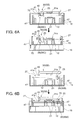
- FIG. 6 describes the opening and closing operation of the valve unit 40 , FIG. 6A showing the opening operation that opens the valve unit 40 in conjunction with the cap 12 sealing the fluid nozzle faces 31 a , and FIG. 6B showing when the valve unit 40 is held in the closed position when the fluid nozzle faces 31 a are sealed by the cap 12 .
- the valve unit 40 includes a valve seat 51 in which an orifice 50 of the internal path 39 is disposed for opening and closing the moisture supply path 35 ; a valve disc 52 that moves to and away from the valve seat 51 to close and open the orifice 50 ; a spring 53 (second spring member) that urges the valve disc 52 to the valve seat 51 ; and a magnetic attraction mechanism 54 that moves the valve disc 52 away from the valve seat 51 against the urging force of the spring 53 .
- the valve disc 52 includes a rod-shaped iron core (magnetic body) 55 , and an elastic body 56 such as rubber attached to the distal end of the iron core 55 , and opens and closes the orifice 50 by moving the elastic body 56 to and away from the valve seat 51 .
- the spring 53 is a compression spring disposed around the iron core 55 .
- the direction D 2 of valve disc 52 movement is perpendicular to the direction D 3 (vertical) in which the operating lever 41 is pushed.
- the magnetic attraction mechanism 54 includes the iron core 55 of the valve disc 52 , and a magnet 57 mounted on the operating lever 41 .
- the magnet 57 is affixed to the operating lever 41 , and moves vertically in conjunction with the operating lever 41 .
- the operating lever 41 reaches the top open position 41 B, the magnet 57 and valve disc 52 are in mutual proximity, and the force of magnetic attraction between the magnet 57 and iron core 55 becomes stronger than the urging force of the spring 53 .
- the valve disc 52 separates from the valve seat 51 due to the force of magnetic attraction, and the orifice 50 opens. More specifically, the valve unit 40 opens and the moisture supply path 35 opens.
- the urging force of the spring 53 becomes stronger than the force of magnetic attraction.
- the urging force of the spring 53 causes the valve disc 52 to contact the valve seat 51 , and close the orifice 50 . More specifically, the valve unit 40 closes and the moisture supply path 35 closes.
- the magnetic attraction mechanism 54 could alternatively be rendered with the magnet 57 disposed to the disc, and a magnetic body disposed to the operating lever 41 , which is nonmagnetic.
- the valve operating mechanism 42 includes the operating lever 41 , the wiper unit 26 (pushing member), a positioning member (not shown in the figure) that contacts the operating lever 41 from below and positions the operating lever 41 to the closed position 41 A, and a spring 60 (first spring member) such as a coil spring that produces urging force F 1 pushing the operating lever 41 down to the positioning member and supports the operating lever 41 at the closed position 41 A.
- the positioning member and the spring 60 are disposed to the moisture discharge head 30 .
- the wiper unit 26 has a protruding part 70 that protrudes up.
- the wiper unit moving mechanism 27 sets the wiper unit 26 to a predetermined pushing position 26 C
- the protruding part 70 of the wiper unit 26 can contact the operating part 41 a of the operating lever 41 of the moisture discharge head 30 at the maintenance position 5 B. More specifically, when at the pushing position 26 C, the protruding part 70 of the wiper unit 26 is positioned directly below the operating lever 41 of the moisture discharge head 30 at the maintenance position 5 B.
- the cap 12 separates from the fluid nozzle faces 31 a and the fluid nozzle faces 31 a are not covered by the cap 12 . Because the wiper unit 26 descends and separates from the moisture discharge head 30 in conjunction with the descent of the unit frame 15 , the operating lever 41 is pushed back by the urging force F 1 of the spring 60 from the open position 41 B to the closed position 41 A. The valve unit 40 is therefore held closed when the fluid nozzle faces 31 a are not covered by the cap 12 .
- the wiper unit 26 when the moisture discharge head 30 is at the maintenance position 5 B, the wiper unit 26 is set to a position away from the pushing position 26 C, and the unit frame 15 rises until the cap 12 reaches the capping position 12 A, the protruding part 70 of the wiper unit 26 that rises with the unit frame 15 does not contact the operating lever 41 as shown in the bottom in FIG. 6B , and the operating lever 41 is not depressed.
- the fluid nozzle faces 31 a are thus sealed by the cap 12 while the valve unit 40 remains closed.
- the wiper unit 26 is moved to the second engagement position 26 B when the wiper unit 26 is set to a position away from the pushing position 26 C.
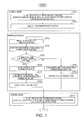
- FIG. 7 is a flow chart of the inkjet head 5 maintenance operation and the operation supplying moisture to the cap 12 .
- the inkjet printer 1 When the inkjet printer 1 is in the standby mode, the inkjet head 5 is at the maintenance position 5 B, and the moisture discharge head 30 is at the maintenance standby position.
- the cap 12 is disposed to the capping position 12 A, and seals the ink nozzle faces 7 of the inkjet head 5 (step ST 1 ). Evaporation of moisture from the ink nozzles is suppressed by sealing the ink nozzle faces 7 with the cap 12 .
- the inkjet head 5 maintenance operation is performed when the inkjet printer 1 is in the standby mode, and the flushing operation that discharges ink from the inkjet head 5 into the cap 12 is performed at a specific time. If ink nozzle clogging is detected, the ink suction operation is performed, causing the suction pump 14 to produce negative pressure in the sealed space formed by the ink nozzle faces 7 and cap 12 , forcibly purging ink from the inkjet head 5 into the cap 12 . The ink nozzle faces 7 are also wiped by the wiper mechanism 13 at a specific time (step ST 2 ).
- the lift mechanism 18 lowers the cap 12 from the capping position 12 A to the capping standby position 12 B where there is no interference with the inkjet head 5 .
- the cap 12 moves to the capping standby position 12 B, the inkjet head 5 is set to the printing position 5 A (step ST 3 ).
- the inkjet head 5 can print to the recording paper 4 conveyed past the printing position P.
- the moisture discharge head moving mechanism 33 moves the moisture discharge head 30 to the maintenance position 5 B (step ST 4 ).
- the inkjet printer 1 continuously counts the open time, that is, how long the ink nozzle faces 7 of the inkjet head 5 and the fluid nozzle faces 31 a are not sealed by the cap 12 , and determines if this cumulative open time exceeds a predetermined setting (step ST 5 ).
- step ST 6 If the cumulative open time exceeds the set time in step ST 5 , there is a low moisture state inside the cap due to evaporation, and the wiper unit moving mechanism 27 moves the wiper unit 26 to the pushing position 26 C (step ST 6 ).
- the lift mechanism 18 then raises the cap 12 from the capping standby position 12 B to the capping position 12 A.
- the protruding part 70 of the wiper unit 26 contacts the operating part 41 a of the operating lever 41 as the cap 12 rises, and pushes the operating lever 41 from the closed position 41 A in the depression direction D 3 to the open position 41 B, the fluid nozzle faces 31 a are sealed by the cap 12 , and the valve unit 40 opens (step ST 7 ).
- the suction pump 14 When the fluid nozzle faces 31 a are sealed by the cap 12 and the valve unit 40 is open, the suction pump 14 operates. As a result, moisture is discharged from the fluid nozzles 31 into the cap 12 . More specifically, moisture is supplied into the cap 12 , and the balance of moisture to moisture in the cap 12 is adjusted (step ST 8 ).
- step ST 5 If in step ST 5 the cumulative open time is not exceeded, the wiper unit moving mechanism 27 moves the wiper unit 26 away from the pushing position 26 C to the second engagement position 26 B (step ST 9 ).
- the lift mechanism 18 then raises the cap 12 from the capping standby position 12 B to the capping position 12 A, and seals the fluid nozzle faces 31 a with the cap 12 (step ST 10 ). Because the protruding part 70 of the wiper unit 26 does not contact the operating lever 41 when the cap 12 rises in step ST 10 , the valve unit 40 is kept closed when the fluid nozzle faces 31 a are sealed by the cap 12 . When the fluid nozzle faces 31 a are sealed by the cap 12 , evaporation of moisture from the cap 12 is suppressed.
- the inkjet printer 1 When printing the print data then ends, the inkjet printer 1 returns to the standby mode. More specifically, the lift mechanism 18 moves the cap 12 to the capping standby position 12 B, and the moisture discharge head moving mechanism 33 moves the moisture discharge head 30 to the maintenance standby position 30 A. When the inkjet head 5 then returns to the maintenance position 5 B, the lift mechanism 18 moves the cap 12 to the capping position and seals the ink nozzle faces 7 of the inkjet head 5 (step ST 11 ).
- the valve unit 40 disposed to the moisture supply path 35 in this embodiment of the invention opens only when the valve operating mechanism 42 seals the fluid nozzle faces 31 a of the moisture discharge head 30 with the cap 12 , and is held closed when the fluid nozzle faces 31 a are not sealed with the cap 12 . As a result, leakage of moisture from the moisture discharge head 30 , and backflow of moisture in the moisture supply path 35 , can be prevented or reduced.
- the wiper unit 26 that moves together with the cap 12 operates the operating lever 41 that opens and closes the valve unit 40 , the wiper unit 26 can perform an opening operation that opens the valve unit 40 in conjunction with moving the cap 12 to seal the moisture discharge head 30 , and a closing operation that closes the valve unit 40 in conjunction with the cap 12 moving away from the moisture discharge head 30 .
- the moisture discharge head moving mechanism 33 is rendered using the wiper unit moving mechanism 27 that moves the wiper unit 26 in this embodiment of the invention, the moisture discharge head moving mechanism 33 can be easily rendered and the cost of manufacturing the inkjet printer 1 can be suppressed.
- this embodiment uses the wiper unit 26 that can move on the unit frame 15 moved vertically by the lift mechanism 18 as the pushing member that depresses the operating lever 41 , opening and closing the valve unit 40 can be controlled by the position of the wiper unit 26 when the cap 12 seals the fluid nozzle faces 31 a of the moisture discharge head 30 at the maintenance position 5 B.
- the pushing member for depressing the operating lever 41 is the wiper unit 26 in the foregoing embodiment, but the invention is not limited to using the wiper unit 26 , and any member that moves together with the cap 12 could be used as the pushing member.
- the pushing member could also be rendered in unison with the cap 12 . In such configurations, however, the pushing member must push constantly on the operating lever 41 and hold the valve unit 40 open when the cap 12 moves away from the capping standby position 12 B to the capping position 12 A and seals the fluid nozzle faces 31 a of the moisture discharge head 30 at the maintenance position 5 B.
- the fluid nozzle faces 31 a of the moisture discharge head 30 can be wiped by the wiper mechanism 13 at the maintenance position 5 B, the fluid nozzle faces 31 a could also be wiped by the wiper mechanism 13 after moisture is supplied through the moisture discharge head 30 into the cap 12 .
- the unit frame 15 rises to set the wiper mechanism 13 to the wiping position where the top edge of the wiper 25 can slide against the ink nozzle faces 7 , and the wiper unit moving mechanism 27 moves the wiper unit 26 in the longitudinal direction to wipe the fluid nozzle faces 31 a with the wiper 25 . This can prevent moisture from dripping off the fluid nozzle faces 31 a.
Landscapes
- Ink Jet (AREA)
- Coating Apparatus (AREA)
Abstract
Description
- 1. Technical Field
- The present invention relates to an inkjet printer that has a cap to cover the ink nozzle face of the inkjet head, and a moisture supply mechanism that supplies a moisturizing fluid into the cap.
- 2. Related Art
- In order to prevent an increase in the viscosity of ink in the ink nozzles from clogging the ink nozzles, inkjet printers cover the ink nozzle face in which the ink nozzles are formed with a cap while the inkjet head is at the maintenance position to suppress evaporation of moisture from the ink nozzles. A flushing operation that ejects ink from the ink nozzles into the cap while the cap is opposite the ink nozzle face is also regularly performed to suppress nozzle clogging. When ink nozzle clogging occurs, an ink suction operation that covers the ink nozzle face with a cap, produces negative pressure in the sealed space formed between the nozzle face and the cap by means of a suction pump, and forcibly expels ink from the ink nozzles into the cap, is performed to eliminate the clogging. The ink expelled from the ink nozzles in the flushing operation and ink suction operation is absorbed by an ink-absorbent material (referred to below as a sponge) such as felt held inside the cap.
- A humectant such as glycerin is contained in the ink that is ejected from the ink nozzles, and as the flushing operation and ink suction operation are performed, the humectant accumulates in the sponge inside the cap. If moisture then evaporates from inside the cap and the balance between the moisture in the cap and the amount of humectant is lost, the humectant will absorb moisture from the sealed space formed by the cap and the ink nozzle face when the ink nozzle face is covered by the cap, thus accelerating evaporation of moisture from the ink nozzles and promoting increased ink viscosity. As a result, the ink nozzles become easily clogged.
- To prevent this from happening, Japanese Unexamined Patent Appl. Pub. JP-A-2009-226719 teaches an inkjet printer that has a moisture supply mechanism to supply moisture into the cap. The moisture supply mechanism in JP-A-2009-226719 has a moisture tank, a moisture discharge head with a fluid nozzle face in which a fluid nozzle for discharging moisture is formed, a moisture supply path that connects the moisture tank and the fluid nozzle, and a suction pump. When the fluid nozzle face is covered by the cap, the suction pump produces negative pressure in the sealed space formed between the cap and the fluid nozzle face, and forcibly discharges moisture supplied from the moisture tank from the moisture discharge head to the cap.
- The moisture supply mechanism described in JP-A-2009-226719 does not require a mechanism that ejects moisture into the moisture discharge head itself. Moisture can also be discharged from the moisture discharge head using the suction pump that is used for the ink suction operation. The cost of manufacturing an inkjet printer with the moisture supply mechanism can therefore be suppressed. However, leakage of moisture from the moisture discharge head or backflow of the moisture in the moisture supply path could occur depending on the location of the moisture tank. If the moisture leaks, the inside of the printer could become wet. If moisture backflow occurs, the amount of moisture discharged into the cap by the suction operation of the suction pump will be unstable, and the moisture level inside the cap cannot be kept at the desired level.
- If a part with a small diameter is formed in the fluid nozzle, the moisture can be prevented from leaking or backflowing by the pressure resistance of the meniscus of the moisture in the fluid nozzle. However, if the diameter of the fluid nozzle is on the order of several ten microns, a hydraulic head of several hundred millimeters cannot be withstood, manufacturing the moisture discharge head is therefore more difficult, and the product manufacturing cost increases.
- An inkjet printer according to the present invention can suppress or prevent wetting by moisture from a moisture discharge head and backflow of the moisture.
- One aspect of the invention is an inkjet printer including: an inkjet head that can move between a printing position and a maintenance position; a cap that seals the ink nozzle face of the inkjet head set to the maintenance position; a cap moving mechanism that moves the cap; and a moisture supply mechanism that supplies moisture to the inside of the cap. The moisture supply mechanism includes a moisture discharge head with a fluid nozzle face in which a fluid nozzle for discharging the moisture is formed; a valve disposed in a moisture supply path connecting a moisture tank with the fluid nozzle; and a valve operating mechanism that holds the valve closed when the fluid nozzle face is not covered by the cap, and opens the valve when the fluid nozzle face is sealed by the cap. The cap moving mechanism moves the cap between a capping position sealing the ink nozzle face of the inkjet head set to the maintenance position, or the fluid nozzle face of the moisture discharge head set to the maintenance position, and a capping standby position removed from the capping position. The valve operating mechanism holding the valve closed when the cap is at the capping standby position, and opening the valve when the cap is at the capping position.
- This aspect of the invention can perform the opening operation of the valve located in the moisture supply path together with the operation moving the cap to seal the moisture discharge head. More specifically, the valve is opened by the valve operating mechanism only when the fluid nozzle face of the moisture discharge head is sealed by the cap, and closed when the fluid nozzle face is not covered by the cap. Leakage of moisture from the moisture discharge head, and backflow of moisture from the moisture discharge head to the moisture tank side can be prevented or reduced.
- Preferably, the moisture supply mechanism includes a moisture discharge head moving mechanism that moves the moisture discharge head to the maintenance position when the inkjet head is at the printing position, and seals the fluid nozzle face with the cap; and a suction mechanism that produces negative pressure in a sealed space formed by the fluid nozzle face and the cap, and discharges moisture from the fluid nozzle, when the fluid nozzle face is sealed by the cap and the valve is open.
- In another aspect of the invention, the valve operating mechanism includes an operating lever that is supported on the moisture discharge head slidably between a closed position for closing the valve and an open position for opening the valve, and a pushing member that, when the cap moves from the capping standby position to the capping position and approaches the moisture discharge head set to the maintenance position, approaches the moisture discharge head with the cap and pushes the operating lever in a depression direction from the closed position to the open position.
- Further preferably in another aspect of the invention, the valve operating mechanism includes a first spring member that supports the operating lever at the closed position, and urges the operating lever to the closed position side when the operating lever is pushed from the closed position to the open position, and when the cap moves from the capping position toward the capping standby position and the pushing member separates from the moisture discharge head, the operating lever is pushed back from the open position to the closed position by a first urging force of the first spring member.
- This configuration can perform the closing operation that closes the valve in conjunction with the operation moving the cap away from the moisture discharge head.
- An inkjet printer according to another aspect of the invention preferably also has: a wiper unit with a wiper for wiping the ink nozzle face of the inkjet head at the maintenance position, or the fluid nozzle face of the moisture discharge head at the maintenance position; a wiper unit moving mechanism that moves the wiper unit parallel to the ink nozzle face or the fluid nozzle face; and a linking mechanism that connects the wiper unit and the moisture discharge head; and the moisture discharge head moving mechanism moves the moisture discharge head between the maintenance position and a maintenance standby position separated from the maintenance position by moving the wiper unit while the wiper unit and the moisture discharge head are connected by the linking mechanism.
- More specifically, by using the wiper unit moving mechanism that moves the wiper unit for the moisture discharge head moving mechanism, the moisture discharge head moving mechanism can be easily configured and the product manufacturing cost can be suppressed.
- An inkjet printer according to another aspect of the invention preferably also has a frame on which the cap, wiper unit, and wiper unit moving mechanism are mounted. The cap moving mechanism moves the cap between the capping position and the capping standby position by moving the frame, and the pushing member is the wiper unit, and can depress the operating lever when the wiper unit is set to a specific pushing position by the wiper unit moving mechanism.
- When the cap moves from the capping standby position toward the capping position and seals the fluid nozzle face of the moisture discharge head set to the maintenance position in this aspect of the invention, the valve can be opened by moving the wiper unit to the pushing position. In addition, if the wiper unit is set to a position separated from the pushing position, the fluid nozzle face can be sealed by the cap while the valve is held closed.
- Further preferably in an inkjet printer according to another aspect of the invention, the valve includes a valve seat in which an orifice for opening and closing the moisture supply path is disposed, a disc that moves in a direction toward and a direction away from the valve seat, and opens and closes the orifice, a second spring member that urges the disc to the valve seat, and a magnetic attraction mechanism that moves the disc in a direction away from the valve seat against the urging force of the second spring member, has either a magnetic body or a magnet mounted on the disc, and the other of the magnetic body or magnet mounted the operating lever, and when the operating lever is depressed to the open position, the magnet and magnetic body approach and the force of magnetic attraction working between the magnet and magnetic body separates the disc from the valve seat and opens the orifice, and when the operating lever moves from the open position to the closed position, the urging force of the second spring member seats the disc on the valve seat and closes the orifice.
- This enables opening and closing the valve by operating an operating lever.
- A valve located in a moisture supply path is opened only when the fluid nozzle face of a moisture discharge head is sealed with a cap by the valve operating mechanism, and is closed when the fluid nozzle face is not covered by the cap. Leakage of moisture from the moisture discharge head, and backflow of moisture from the moisture discharge head to the moisture tank side can therefore be prevented or reduced.
- Other objects and attainments together with a fuller understanding of the invention will become apparent and appreciated by referring to the following description and claims taken in conjunction with the accompanying drawings.
-
FIG. 1 is an oblique view of an inkjet printer without the printer case. -
FIG. 2 is a section view through line A-A inFIG. 1 . -
FIG. 3 is an oblique view of the moisture discharge head, moisture supply path, and guide rail. -
FIG. 4 shows the moisture discharge head moving mechanism. -
FIG. 5 shows a valve unit and valve operating mechanism. -
FIG. 6 describes the operation of opening and closing the valve unit. -
FIG. 7 is a flow chart of the moisture supply operation. - An inkjet printer according to a preferred embodiment of the invention is described below with reference to the accompanying figures.
-
FIG. 1 is an oblique view showing main parts of an inkjet printer according to this embodiment of the invention with the printer case removed.FIG. 2 is a section view through line A-A inFIG. 1 ,FIG. 2A showing the moisture discharge head at the maintenance standby position, andFIG. 2B showing the moisture discharge head at the maintenance position.FIG. 3 is an oblique view of the moisture discharge head, moisture supply path, and guide rail from below the back of the printer. - As shown in
FIG. 1 , the inkjet printer 1 conveysrecording paper 4 pulled from apaper roll 3 stored in aroll paper compartment 2 at the back of the printer in a conveyance direction D1 toward the front of the printer along a rollpaper conveyance path 6 past the printing position P of theinkjet head 5, and prints. Theinkjet head 5 is mounted on acarriage 8 with the ink nozzle faces 7 in which the ink nozzles are formed facing down, and rotates between aprinting position 5A indicated by a solid line inFIG. 1 and themaintenance position 5B position indicated by the double-dot dash line. An ink supply mechanism (not shown in the figure) for supplying ink from anink tank 9 located below the printing position P is connected to theinkjet head 5, and printing to therecording paper 4 passing the printing position P is possible when theinkjet head 5 is at theprinting position 5A. Themaintenance position 5B is offset to the side of theroll paper compartment 2 and the rollpaper conveyance path 6. - A
head maintenance unit 11 is located below themaintenance position 5B. Thehead maintenance unit 11 includes acap 12 that seals the ink nozzle faces 7 of theinkjet head 5 at themaintenance position 5B,wiper mechanism 13 that wipes the ink nozzle faces 7 of theinkjet head 5 at themaintenance position 5B, and suction pump 14 (suction device,FIG. 2 ) that performs an ink suction operation that forcibly discharges ink from thecap 12. Thecap 12,wiper mechanism 13, andsuction pump 14 are mounted on aunit frame 15. Theunit frame 15 is supported movably vertically on a base frame 16 (seeFIG. 4 ), and moves up and down on thebase frame 16 by means of a lift mechanism 18 (cap moving mechanism) with adrive motor 17. - A lip made of butyl rubber, for example, is formed around the circumference of the open edge of the
cap 12, and an ink absorbent member (referred to herein as a sponge) made of felt or other suitable material for absorbing the ink ejected from theinkjet head 5 is held inside thecap 12. Thecap 12 is supported on theunit frame 15 by a spring 21 (FIG. 4 ). As theunit frame 15 moves up and down, thecap 12 moves vertically between acapping position 12A where the ink nozzle faces 7 of theinkjet head 5 are sealed at themaintenance position 5B, and acapping standby position 12B separated down from thecapping position 12A. - The
wiper mechanism 13 has awiper unit 26 that carries awiper 25, and a wiperunit moving mechanism 27 that moves thewiper unit 26 in the direction between the front and back of the printer (referred to as the longitudinal direction) parallel to the ink nozzle faces 7 (FIG. 2 ). When the top edge of thewiper 25 is set by the vertical movement of theunit frame 15 to the wiping position (not shown in the figure) where thewiper 25 can slide against the ink nozzle faces 7, thewiper mechanism 13 moves thewiper unit 26 in the longitudinal direction by means of the wiperunit moving mechanism 27, and wipes the ink nozzle faces 7 with thewiper 25. - When the ink nozzle faces 7 are sealed by the
cap 12, thesuction pump 14 produces negative pressure in the sealed space formed by the ink nozzle faces 7 and cap 12 at a specific time, and discharges ink from the ink nozzles. - A
moisture discharge head 30 that supplies moisture into thecap 12 is disposed behind themaintenance position 5B. The moisture is water or a solution of water and a preservative. - As shown in
FIG. 2 andFIG. 3 , themoisture discharge head 30 is mounted on a pair ofguide rails 32 that extend in the longitudinal direction with the fluid nozzle faces 31 a in which thefluid nozzles 31 that discharge the moisture are formed facing down. Themoisture discharge head 30 is moved by a moisture dischargehead moving mechanism 33 along the guide rails 32 between themaintenance position 5B and amaintenance standby position 30A removed to the back of the printer from themaintenance position 5B. Themoisture discharge head 30 is at themaintenance standby position 30A inFIG. 1 andFIG. 2A , and inFIG. 2B themoisture discharge head 30 is at themaintenance position 5B. Theinkjet head 5 andmoisture discharge head 30 are selectively set to themaintenance position 5B. The moisture dischargehead moving mechanism 33 is rendered using thewiper mechanism 13. - The fluid nozzle faces 31 a of the
moisture discharge head 30 have the same shape as the ink nozzle faces 7 of theinkjet head 5. Therefore, when themoisture discharge head 30 is set by the moisture dischargehead moving mechanism 33 to themaintenance position 5B, the fluid nozzle faces 31 a can be sealed by thecap 12 moving to thecapping position 12A. In addition, when thewiper mechanism 13 is set to the wiping position after themoisture discharge head 30 is moved to themaintenance position 5B, the fluid nozzle faces 31 a of themoisture discharge head 30 can be wiped by thewiper mechanism 13. - A
moisture tank 34 is located below the printing position P in front of the ink tank 9 (FIG. 1 ). Themoisture tank 34 and thefluid nozzles 31 of themoisture discharge head 30 are connected by amoisture supply path 35. As shown inFIG. 3 , themoisture supply path 35 includes from the downstream end aflat path 37 formed on arigid substrate 36, aflexible tube 38, and aninternal path 39 formed inside the moisture discharge head 30 (seeFIG. 5 ). A valve unit (valve) 40 for opening and closing themoisture supply path 35 is disposed in theinternal path 39. Thevalve unit 40 is disposed to the part of themoisture discharge head 30 towards the back of the printer. - An operating
lever 41 that slides vertically and opens and closes thevalve unit 40 is attached to thevalve unit 40. The operatinglever 41 is supported on themoisture discharge head 30 slidably between a closed position 40A (seeFIG. 5B ) for closing thevalve unit 40, and an open position 40B (seeFIG. 5C ) for opening thevalve unit 40. The operatingpart 41 a of the operatinglever 41 protrudes down from themoisture discharge head 30. The operatinglever 41 renders avalve operating mechanism 42 that can hold thevalve unit 40 closed when the fluid nozzle faces 31 a of themoisture discharge head 30 are not covered by thewiper unit 26 of thewiper mechanism 13 and thecap 12, and open thevalve unit 40 when the fluid nozzle faces 31 a are sealed by thecap 12. - When the fluid nozzle faces 31 a are sealed by the
cap 12 and thevalve unit 40 is opened by thevalve operating mechanism 42, negative pressure can be produced in the sealed space formed by the fluid nozzle faces 31 a andcap 12 by driving thesuction pump 14, and moisture can be discharged from thefluid nozzles 31 into thecap 12. More specifically, themoisture discharge head 30, moisture dischargehead moving mechanism 33,moisture tank 34,moisture supply path 35,valve unit 40,valve operating mechanism 42, andsuction pump 14 render amoisture supply mechanism 43 that supplies moisture to thecap 12. -
FIG. 4 describes the moisture dischargehead moving mechanism 33. The moisture dischargehead moving mechanism 33 uses the wiperunit moving mechanism 27 andwiper unit 26 to move themoisture discharge head 30 between themaintenance position 5B andmaintenance standby position 30A. The moisture dischargehead moving mechanism 33 has alinking mechanism 45 that connects thewiper unit 26 andmoisture discharge head 30. - The wiper
unit moving mechanism 27 has a wiperunit guide shaft 46 that extends in the longitudinal direction below and between the pair of guide rails 32. The wiperunit guide shaft 46 extends parallel to the ink nozzle faces 7 of theinkjet head 5 and the fluid nozzle faces 31 a of themoisture discharge head 30, and the front and back end parts are supported from below by aspring 47. Thewiper unit 26 is attached to the wiperunit guide shaft 46 and moves in the longitudinal direction along the wiperunit guide shaft 46. A configuration that uses the wiperunit guide shaft 46 as a lead screw, and has a threaded hole in thewiper unit 26 that mates with the lead screw, can be used as the wiperunit moving mechanism 27. - The linking
mechanism 45 includes a protrudingpart 48 that protrudes down from the bottom part of the front of themoisture discharge head 30, and arecess 49 disposed in thewiper unit 26 to engage the protrudingpart 48. - To move the
moisture discharge head 30 from themaintenance standby position 30A shown inFIG. 4A to themaintenance position 5B shown inFIG. 4D andFIG. 4E , the moisture dischargehead moving mechanism 33 first lowers theunit frame 15 by means of thelift mechanism 18 and sets thewiper mechanism 13 to a position where it will not interfere with themoisture discharge head 30. Next, as shown inFIG. 4B , the wiperunit moving mechanism 27 moves thewiper unit 26 toward the back of the printer to afirst engagement position 26A where therecess 49 is positioned directly below the protrudingpart 48 of themoisture discharge head 30 at themaintenance standby position 30A. Thelift mechanism 18 then raises theunit frame 15, causing thewiper unit 26 to rise, engaging therecess 49 of thewiper unit 26 and the protrudingpart 48 of themoisture discharge head 30, and connecting thewiper unit 26 and themoisture discharge head 30 as shown inFIG. 4C . - The wiper
unit moving mechanism 27 then moves thewiper unit 26 toward the front of the printer. As a result, themoisture discharge head 30 connected to thewiper unit 26 moves to themaintenance position 5B as shown inFIG. 4D . - When the
unit frame 15 is raised by thelift mechanism 18, the fluid nozzle faces 31 a of themoisture discharge head 30 can be covered by thecap 12 as shown inFIG. 4E . - The above operation is reversed to move the
moisture discharge head 30 from themaintenance position 5B to themaintenance standby position 30A. More specifically, if themoisture discharge head 30 andwiper unit 26 are disconnected, lowering theunit frame 15 by means of thelift mechanism 18 causes thewiper mechanism 13 to descend to a position not interfering with themoisture discharge head 30. Next, the wiperunit moving mechanism 27 moves thewiper unit 26 toward the printer front to thesecond engagement position 26B where therecess 49 is directly below the protrudingpart 48 of themoisture discharge head 30 at themaintenance standby position 30A. Thewiper unit 26 is then raised by thelift mechanism 18 raising theunit frame 15, engaging therecess 49 in thewiper unit 26 with the protrudingpart 48 of themoisture discharge head 30. As a result, thewiper unit 26 and themoisture discharge head 30 are connected again as shown inFIG. 4D . The wiperunit moving mechanism 27 then moves thewiper unit 26 to the back of the printer. As a result, themoisture discharge head 30 engaged with thewiper unit 26 moves to themaintenance standby position 30A, returning to the position shown inFIG. 4C . - The
valve unit 40 andvalve operating mechanism 42 are described next with reference toFIG. 5 .FIG. 5A is a partial back view of themoisture discharge head 30 from the back side of the printer.FIG. 5B andFIG. 5C are section views through line B-B inFIG. 5A ,FIG. 5B showing the operatinglever 41 at theclosed position 41A, andFIG. 5C showing the operatinglever 41 at theopen position 41B.FIG. 6 describes the opening and closing operation of thevalve unit 40,FIG. 6A showing the opening operation that opens thevalve unit 40 in conjunction with thecap 12 sealing the fluid nozzle faces 31 a, andFIG. 6B showing when thevalve unit 40 is held in the closed position when the fluid nozzle faces 31 a are sealed by thecap 12. - The
valve unit 40 includes avalve seat 51 in which anorifice 50 of theinternal path 39 is disposed for opening and closing themoisture supply path 35; avalve disc 52 that moves to and away from thevalve seat 51 to close and open theorifice 50; a spring 53 (second spring member) that urges thevalve disc 52 to thevalve seat 51; and amagnetic attraction mechanism 54 that moves thevalve disc 52 away from thevalve seat 51 against the urging force of thespring 53. - The
valve disc 52 includes a rod-shaped iron core (magnetic body) 55, and anelastic body 56 such as rubber attached to the distal end of theiron core 55, and opens and closes theorifice 50 by moving theelastic body 56 to and away from thevalve seat 51. Thespring 53 is a compression spring disposed around theiron core 55. The direction D2 ofvalve disc 52 movement is perpendicular to the direction D3 (vertical) in which the operatinglever 41 is pushed. - The
magnetic attraction mechanism 54 includes theiron core 55 of thevalve disc 52, and amagnet 57 mounted on the operatinglever 41. Themagnet 57 is affixed to the operatinglever 41, and moves vertically in conjunction with the operatinglever 41. When the operatinglever 41 reaches the topopen position 41B, themagnet 57 andvalve disc 52 are in mutual proximity, and the force of magnetic attraction between themagnet 57 andiron core 55 becomes stronger than the urging force of thespring 53. As a result, thevalve disc 52 separates from thevalve seat 51 due to the force of magnetic attraction, and theorifice 50 opens. More specifically, thevalve unit 40 opens and themoisture supply path 35 opens. Because the distance between themagnet 57 and thevalve disc 52 increases when the operatinglever 41 moves from theopen position 41B down to theclosed position 41A, the urging force of thespring 53 becomes stronger than the force of magnetic attraction. As a result, the urging force of thespring 53 causes thevalve disc 52 to contact thevalve seat 51, and close theorifice 50. More specifically, thevalve unit 40 closes and themoisture supply path 35 closes. Note that themagnetic attraction mechanism 54 could alternatively be rendered with themagnet 57 disposed to the disc, and a magnetic body disposed to the operatinglever 41, which is nonmagnetic. - The
valve operating mechanism 42 includes the operatinglever 41, the wiper unit 26 (pushing member), a positioning member (not shown in the figure) that contacts the operatinglever 41 from below and positions the operatinglever 41 to theclosed position 41A, and a spring 60 (first spring member) such as a coil spring that produces urging force F1 pushing the operatinglever 41 down to the positioning member and supports the operatinglever 41 at theclosed position 41A. The positioning member and thespring 60 are disposed to themoisture discharge head 30. - As shown in
FIG. 6 , thewiper unit 26 has a protrudingpart 70 that protrudes up. When the wiperunit moving mechanism 27 sets thewiper unit 26 to a predetermined pushingposition 26C, the protrudingpart 70 of thewiper unit 26 can contact the operatingpart 41 a of the operatinglever 41 of themoisture discharge head 30 at themaintenance position 5B. More specifically, when at the pushingposition 26C, the protrudingpart 70 of thewiper unit 26 is positioned directly below the operatinglever 41 of themoisture discharge head 30 at themaintenance position 5B. - As shown at the top in
FIG. 6A , when themoisture discharge head 30 is at themaintenance position 5B, thewiper unit 26 is at the pushingposition 26C, and theunit frame 15 rises until thecap 12 reaches thecapping position 12A, the protrudingpart 70 of thewiper unit 26 that rises with theunit frame 15 contacts the operatinglever 41 from the bottom as shown in the bottom inFIG. 6A , and pushes the operatinglever 41 up in the depression direction D3 from theclosed position 41A to theopen position 41B. As a result, the fluid nozzle faces 31 a are sealed by thecap 12 and thevalve unit 40 opens. - When the
unit frame 15 then descends from thecapping position 12A to thecapping standby position 12B, thecap 12 separates from the fluid nozzle faces 31 a and the fluid nozzle faces 31 a are not covered by thecap 12. Because thewiper unit 26 descends and separates from themoisture discharge head 30 in conjunction with the descent of theunit frame 15, the operatinglever 41 is pushed back by the urging force F1 of thespring 60 from theopen position 41B to theclosed position 41A. Thevalve unit 40 is therefore held closed when the fluid nozzle faces 31 a are not covered by thecap 12. - Note that, as shown in the top in
FIG. 6B , when themoisture discharge head 30 is at themaintenance position 5B, thewiper unit 26 is set to a position away from the pushingposition 26C, and theunit frame 15 rises until thecap 12 reaches thecapping position 12A, the protrudingpart 70 of thewiper unit 26 that rises with theunit frame 15 does not contact the operatinglever 41 as shown in the bottom inFIG. 6B , and the operatinglever 41 is not depressed. The fluid nozzle faces 31 a are thus sealed by thecap 12 while thevalve unit 40 remains closed. In this embodiment thewiper unit 26 is moved to thesecond engagement position 26B when thewiper unit 26 is set to a position away from the pushingposition 26C. -
FIG. 7 is a flow chart of theinkjet head 5 maintenance operation and the operation supplying moisture to thecap 12. When the inkjet printer 1 is in the standby mode, theinkjet head 5 is at themaintenance position 5B, and themoisture discharge head 30 is at the maintenance standby position. Thecap 12 is disposed to thecapping position 12A, and seals the ink nozzle faces 7 of the inkjet head 5 (step ST1). Evaporation of moisture from the ink nozzles is suppressed by sealing the ink nozzle faces 7 with thecap 12. - The
inkjet head 5 maintenance operation is performed when the inkjet printer 1 is in the standby mode, and the flushing operation that discharges ink from theinkjet head 5 into thecap 12 is performed at a specific time. If ink nozzle clogging is detected, the ink suction operation is performed, causing thesuction pump 14 to produce negative pressure in the sealed space formed by the ink nozzle faces 7 andcap 12, forcibly purging ink from theinkjet head 5 into thecap 12. The ink nozzle faces 7 are also wiped by thewiper mechanism 13 at a specific time (step ST2). - When the inkjet printer 1 receives print data supplied from an external device, the
lift mechanism 18 lowers thecap 12 from thecapping position 12A to thecapping standby position 12B where there is no interference with theinkjet head 5. When thecap 12 moves to thecapping standby position 12B, theinkjet head 5 is set to theprinting position 5A (step ST3). When at theprinting position 5A, theinkjet head 5 can print to therecording paper 4 conveyed past the printing position P. - When the
inkjet head 5 moves to theprinting position 5A, the moisture dischargehead moving mechanism 33 moves themoisture discharge head 30 to themaintenance position 5B (step ST4). - The inkjet printer 1 continuously counts the open time, that is, how long the ink nozzle faces 7 of the
inkjet head 5 and the fluid nozzle faces 31 a are not sealed by thecap 12, and determines if this cumulative open time exceeds a predetermined setting (step ST5). - If the cumulative open time exceeds the set time in step ST5, there is a low moisture state inside the cap due to evaporation, and the wiper
unit moving mechanism 27 moves thewiper unit 26 to the pushingposition 26C (step ST6). Thelift mechanism 18 then raises thecap 12 from thecapping standby position 12B to thecapping position 12A. As a result, the protrudingpart 70 of thewiper unit 26 contacts the operatingpart 41 a of the operatinglever 41 as thecap 12 rises, and pushes the operatinglever 41 from theclosed position 41A in the depression direction D3 to theopen position 41B, the fluid nozzle faces 31 a are sealed by thecap 12, and thevalve unit 40 opens (step ST7). - When the fluid nozzle faces 31 a are sealed by the
cap 12 and thevalve unit 40 is open, thesuction pump 14 operates. As a result, moisture is discharged from thefluid nozzles 31 into thecap 12. More specifically, moisture is supplied into thecap 12, and the balance of moisture to moisture in thecap 12 is adjusted (step ST8). - If in step ST5 the cumulative open time is not exceeded, the wiper
unit moving mechanism 27 moves thewiper unit 26 away from the pushingposition 26C to thesecond engagement position 26B (step ST9). Thelift mechanism 18 then raises thecap 12 from thecapping standby position 12B to thecapping position 12A, and seals the fluid nozzle faces 31 a with the cap 12 (step ST10). Because the protrudingpart 70 of thewiper unit 26 does not contact the operatinglever 41 when thecap 12 rises in step ST10, thevalve unit 40 is kept closed when the fluid nozzle faces 31 a are sealed by thecap 12. When the fluid nozzle faces 31 a are sealed by thecap 12, evaporation of moisture from thecap 12 is suppressed. - When printing the print data then ends, the inkjet printer 1 returns to the standby mode. More specifically, the
lift mechanism 18 moves thecap 12 to thecapping standby position 12B, and the moisture dischargehead moving mechanism 33 moves themoisture discharge head 30 to themaintenance standby position 30A. When theinkjet head 5 then returns to themaintenance position 5B, thelift mechanism 18 moves thecap 12 to the capping position and seals the ink nozzle faces 7 of the inkjet head 5 (step ST11). - The
valve unit 40 disposed to themoisture supply path 35 in this embodiment of the invention opens only when thevalve operating mechanism 42 seals the fluid nozzle faces 31 a of themoisture discharge head 30 with thecap 12, and is held closed when the fluid nozzle faces 31 a are not sealed with thecap 12. As a result, leakage of moisture from themoisture discharge head 30, and backflow of moisture in themoisture supply path 35, can be prevented or reduced. - In addition, because the
wiper unit 26 that moves together with thecap 12 operates the operatinglever 41 that opens and closes thevalve unit 40, thewiper unit 26 can perform an opening operation that opens thevalve unit 40 in conjunction with moving thecap 12 to seal themoisture discharge head 30, and a closing operation that closes thevalve unit 40 in conjunction with thecap 12 moving away from themoisture discharge head 30. - In addition, because the moisture discharge
head moving mechanism 33 is rendered using the wiperunit moving mechanism 27 that moves thewiper unit 26 in this embodiment of the invention, the moisture dischargehead moving mechanism 33 can be easily rendered and the cost of manufacturing the inkjet printer 1 can be suppressed. - Furthermore, because this embodiment uses the
wiper unit 26 that can move on theunit frame 15 moved vertically by thelift mechanism 18 as the pushing member that depresses the operatinglever 41, opening and closing thevalve unit 40 can be controlled by the position of thewiper unit 26 when thecap 12 seals the fluid nozzle faces 31 a of themoisture discharge head 30 at themaintenance position 5B. - The pushing member for depressing the operating
lever 41 is thewiper unit 26 in the foregoing embodiment, but the invention is not limited to using thewiper unit 26, and any member that moves together with thecap 12 could be used as the pushing member. The pushing member could also be rendered in unison with thecap 12. In such configurations, however, the pushing member must push constantly on the operatinglever 41 and hold thevalve unit 40 open when thecap 12 moves away from thecapping standby position 12B to thecapping position 12A and seals the fluid nozzle faces 31 a of themoisture discharge head 30 at themaintenance position 5B. - In addition, because the fluid nozzle faces 31 a of the
moisture discharge head 30 can be wiped by thewiper mechanism 13 at themaintenance position 5B, the fluid nozzle faces 31 a could also be wiped by thewiper mechanism 13 after moisture is supplied through themoisture discharge head 30 into thecap 12. More specifically, theunit frame 15 rises to set thewiper mechanism 13 to the wiping position where the top edge of thewiper 25 can slide against the ink nozzle faces 7, and the wiperunit moving mechanism 27 moves thewiper unit 26 in the longitudinal direction to wipe the fluid nozzle faces 31 a with thewiper 25. This can prevent moisture from dripping off the fluid nozzle faces 31 a.
Claims (7)
Applications Claiming Priority (2)
| Application Number | Priority Date | Filing Date | Title |
|---|---|---|---|
| JP2011071867A JP5765005B2 (en) | 2011-03-29 | 2011-03-29 | inkjet printer |
| JP2011-071867 | 2011-03-29 |
Publications (2)
| Publication Number | Publication Date |
|---|---|
| US20120249672A1 true US20120249672A1 (en) | 2012-10-04 |
| US8714700B2 US8714700B2 (en) | 2014-05-06 |
Family
ID=46926666
Family Applications (1)
| Application Number | Title | Priority Date | Filing Date |
|---|---|---|---|
| US13/429,634 Active US8714700B2 (en) | 2011-03-29 | 2012-03-26 | Inkjet printer |
Country Status (3)
| Country | Link |
|---|---|
| US (1) | US8714700B2 (en) |
| JP (1) | JP5765005B2 (en) |
| CN (1) | CN102729635B (en) |
Cited By (4)
| Publication number | Priority date | Publication date | Assignee | Title |
|---|---|---|---|---|
| US9643413B2 (en) * | 2014-03-26 | 2017-05-09 | Canon Kabushiki Kaisha | Printing apparatus and leakage detection method of the same |
| EP3330090A1 (en) * | 2016-12-01 | 2018-06-06 | KYOCERA Document Solutions Inc. | Inkjet recording apparatus |
| CN109551895A (en) * | 2017-09-27 | 2019-04-02 | 卡西欧计算机株式会社 | Drawing device, drawing method, and recording medium |
| CN114206591A (en) * | 2019-05-23 | 2022-03-18 | 通用电气公司 | Cleaning system for additive manufacturing apparatus and method of using same |
Families Citing this family (1)
| Publication number | Priority date | Publication date | Assignee | Title |
|---|---|---|---|---|
| CN120003165A (en) * | 2025-03-13 | 2025-05-16 | 广州精陶机电设备有限公司 | Printing System |
Citations (13)
| Publication number | Priority date | Publication date | Assignee | Title |
|---|---|---|---|---|
| US6007177A (en) * | 1994-11-30 | 1999-12-28 | Canon Kabushiki Kaisha | Cap for ink jet recording head with rinsing liquid supplied thereto |
| US6158838A (en) * | 1998-12-10 | 2000-12-12 | Eastman Kodak Company | Method and apparatus for cleaning and capping a print head in an ink jet printer |
| US6342105B1 (en) * | 1997-11-21 | 2002-01-29 | Fuji Xerox Co., Ltd. | Washing solution for ink jet head, method for producing the same, and method for washing ink jet head using the same |
| US20020060713A1 (en) * | 2000-11-15 | 2002-05-23 | Seiko Epson Corporation | Liquid ejecting apparatus and method of cleaning an ejection head |
| US20020122084A1 (en) * | 2001-02-27 | 2002-09-05 | Makoto Shihoh | Liquid ejection apparatus |
| US6682165B2 (en) * | 2001-10-30 | 2004-01-27 | Hewlett-Packard Development Company, L.P. | Wiping fluid spray system for inkjet printhead |
| US6802588B2 (en) * | 2002-08-26 | 2004-10-12 | Eastman Kodak Company | Fluid jet apparatus and method for cleaning inkjet printheads |
| US20050168517A1 (en) * | 2004-01-30 | 2005-08-04 | Seiko Epson Corporation | Droplet jetting apparatus, method of operating droplet jetting apparatus, and device manufacturing method |
| US20060274110A1 (en) * | 2005-06-02 | 2006-12-07 | Kang Seung-Wook | Ink-jet image forming apparatus and method of cleaning printbar |
| US20070081056A1 (en) * | 2005-10-12 | 2007-04-12 | Seiko Epson Corporation | Valve device, liquid supply apparatus, and liquid ejection apparatus |
| US20090021564A1 (en) * | 2007-07-20 | 2009-01-22 | Seiko Epson Corporation | Fluid ejecting apparatus and fluid filling method of fluid ejecting apparatus |
| US7753474B2 (en) * | 2006-02-17 | 2010-07-13 | Seiko Epson Corporation | Droplet ejection apparatus, method for recovering droplet ejection head, method for forming thin film, and liquid crystal display |
| US20100302309A1 (en) * | 2009-05-29 | 2010-12-02 | Brother Kogyo Kabushiki Kaisha | Ink Jet Printer |
Family Cites Families (11)
| Publication number | Priority date | Publication date | Assignee | Title |
|---|---|---|---|---|
| JP2000062213A (en) * | 1998-08-13 | 2000-02-29 | Citizen Watch Co Ltd | Driving method for ink-jet recording apparatus |
| JP2001018408A (en) * | 1999-07-09 | 2001-01-23 | Seiko Epson Corp | INK JET RECORDING APPARATUS AND MOISTURE LIQUID DISCHARGE CONTROL METHOD IN THE APPARATUS |
| JP3428633B2 (en) | 1999-11-10 | 2003-07-22 | 富士ゼロックス株式会社 | Printhead protection device and operation control method thereof |
| JP2003320674A (en) * | 2002-05-08 | 2003-11-11 | Seiko Epson Corp | Inkjet recorder |
| JP3960246B2 (en) * | 2003-03-28 | 2007-08-15 | ブラザー工業株式会社 | Inkjet printer |
| JP4547943B2 (en) * | 2004-03-08 | 2010-09-22 | ブラザー工業株式会社 | Inkjet printer |
| JP5076766B2 (en) * | 2007-09-20 | 2012-11-21 | セイコーエプソン株式会社 | Liquid ejector |
| JP4912344B2 (en) | 2008-03-21 | 2012-04-11 | 富士フイルム株式会社 | Barrier laminate and production method thereof, barrier film substrate, device and optical member |
| JP2009226719A (en) * | 2008-03-21 | 2009-10-08 | Seiko Epson Corp | Fluid jetting device |
| JP2009285982A (en) * | 2008-05-29 | 2009-12-10 | Sony Corp | Liquid delivery device |
| JP5245799B2 (en) | 2008-12-16 | 2013-07-24 | セイコーエプソン株式会社 | Fluid ejection device |
-
2011
- 2011-03-29 JP JP2011071867A patent/JP5765005B2/en not_active Expired - Fee Related
-
2012
- 2012-03-26 US US13/429,634 patent/US8714700B2/en active Active
- 2012-03-28 CN CN201210085191.7A patent/CN102729635B/en not_active Expired - Fee Related
Patent Citations (13)
| Publication number | Priority date | Publication date | Assignee | Title |
|---|---|---|---|---|
| US6007177A (en) * | 1994-11-30 | 1999-12-28 | Canon Kabushiki Kaisha | Cap for ink jet recording head with rinsing liquid supplied thereto |
| US6342105B1 (en) * | 1997-11-21 | 2002-01-29 | Fuji Xerox Co., Ltd. | Washing solution for ink jet head, method for producing the same, and method for washing ink jet head using the same |
| US6158838A (en) * | 1998-12-10 | 2000-12-12 | Eastman Kodak Company | Method and apparatus for cleaning and capping a print head in an ink jet printer |
| US20020060713A1 (en) * | 2000-11-15 | 2002-05-23 | Seiko Epson Corporation | Liquid ejecting apparatus and method of cleaning an ejection head |
| US20020122084A1 (en) * | 2001-02-27 | 2002-09-05 | Makoto Shihoh | Liquid ejection apparatus |
| US6682165B2 (en) * | 2001-10-30 | 2004-01-27 | Hewlett-Packard Development Company, L.P. | Wiping fluid spray system for inkjet printhead |
| US6802588B2 (en) * | 2002-08-26 | 2004-10-12 | Eastman Kodak Company | Fluid jet apparatus and method for cleaning inkjet printheads |
| US20050168517A1 (en) * | 2004-01-30 | 2005-08-04 | Seiko Epson Corporation | Droplet jetting apparatus, method of operating droplet jetting apparatus, and device manufacturing method |
| US20060274110A1 (en) * | 2005-06-02 | 2006-12-07 | Kang Seung-Wook | Ink-jet image forming apparatus and method of cleaning printbar |
| US20070081056A1 (en) * | 2005-10-12 | 2007-04-12 | Seiko Epson Corporation | Valve device, liquid supply apparatus, and liquid ejection apparatus |
| US7753474B2 (en) * | 2006-02-17 | 2010-07-13 | Seiko Epson Corporation | Droplet ejection apparatus, method for recovering droplet ejection head, method for forming thin film, and liquid crystal display |
| US20090021564A1 (en) * | 2007-07-20 | 2009-01-22 | Seiko Epson Corporation | Fluid ejecting apparatus and fluid filling method of fluid ejecting apparatus |
| US20100302309A1 (en) * | 2009-05-29 | 2010-12-02 | Brother Kogyo Kabushiki Kaisha | Ink Jet Printer |
Cited By (11)
| Publication number | Priority date | Publication date | Assignee | Title |
|---|---|---|---|---|
| US9643413B2 (en) * | 2014-03-26 | 2017-05-09 | Canon Kabushiki Kaisha | Printing apparatus and leakage detection method of the same |
| US10406837B2 (en) | 2014-03-26 | 2019-09-10 | Canon Kabushiki Kaisha | Printing apparatus and leakage detection method of the same |
| EP3330090A1 (en) * | 2016-12-01 | 2018-06-06 | KYOCERA Document Solutions Inc. | Inkjet recording apparatus |
| CN109551895A (en) * | 2017-09-27 | 2019-04-02 | 卡西欧计算机株式会社 | Drawing device, drawing method, and recording medium |
| US20200113306A1 (en) * | 2017-09-27 | 2020-04-16 | Casio Computer Co., Ltd. | Drawing device, drawing method and storage medium |
| US10702039B2 (en) | 2017-09-27 | 2020-07-07 | Casio Computer Co., Ltd. | Drawing device, drawing method and storage medium |
| US10813431B2 (en) * | 2017-09-27 | 2020-10-27 | Casio Computer Co., Ltd. | Drawing device, drawing method and storage medium |
| CN113022157A (en) * | 2017-09-27 | 2021-06-25 | 卡西欧计算机株式会社 | Drawing device |
| CN114206591A (en) * | 2019-05-23 | 2022-03-18 | 通用电气公司 | Cleaning system for additive manufacturing apparatus and method of using same |
| US20220242044A1 (en) * | 2019-05-23 | 2022-08-04 | General Electric Company | Cleaning systems for additive manufacturing apparatuses and methods for using the same |
| US12280596B2 (en) * | 2019-05-23 | 2025-04-22 | General Electric Company | Cleaning systems for additive manufacturing apparatuses and methods for using the same |
Also Published As
| Publication number | Publication date |
|---|---|
| CN102729635B (en) | 2014-12-03 |
| CN102729635A (en) | 2012-10-17 |
| US8714700B2 (en) | 2014-05-06 |
| JP5765005B2 (en) | 2015-08-19 |
| JP2012206291A (en) | 2012-10-25 |
Similar Documents
| Publication | Publication Date | Title |
|---|---|---|
| US8714700B2 (en) | Inkjet printer | |
| CN108177441B (en) | liquid ejection device | |
| JP5298780B2 (en) | Liquid supply apparatus, printing apparatus, and control method of liquid supply apparatus | |
| US9221263B2 (en) | Inkjet recording device and nozzle surface wiping method for an inkjet recording device | |
| JP5599693B2 (en) | Inkjet printer regulator and inkjet printer | |
| US20160052279A1 (en) | Printing device | |
| JPH0957991A (en) | Ink jet recording device | |
| JP2007050602A (en) | Head maintenance device and ink jet recording apparatus provided with the same | |
| JP5732828B2 (en) | Ink jet recording apparatus and ink nozzle surface wiping method of ink jet recording apparatus | |
| JP2009190285A (en) | Liquid ejection apparatus and printing apparatus | |
| JP2004237620A (en) | Liquid injection device | |
| JP2012106429A (en) | Liquid jet apparatus | |
| JP2003191481A (en) | Ink jet recording device | |
| JP2012206292A (en) | Inkjet printer | |
| JP2010221460A (en) | Fluid ejection device | |
| JP2002103650A (en) | Ink jet recording apparatus and print head cleaning control method in the same | |
| JP2012192661A (en) | Valve mechanism and liquid ejecting apparatus | |
| JP2001158110A (en) | Waste ink housing device, waste ink container and ink jet recorder | |
| JP2012106430A (en) | Liquid jet apparatus | |
| JP3829987B2 (en) | Liquid ejector | |
| JP2008149483A (en) | Recording apparatus cleaning method and recording apparatus | |
| JP2006103056A (en) | Recording apparatus and ink supply method | |
| JP2018094735A (en) | Liquid injection device | |
| JP5505273B2 (en) | Liquid ejection device | |
| JP4016415B2 (en) | Inkjet recording device |
Legal Events
| Date | Code | Title | Description |
|---|---|---|---|
| AS | Assignment |
Owner name: SEIKO EPSON CORPORATION, JAPAN Free format text: ASSIGNMENT OF ASSIGNORS INTEREST;ASSIGNOR:INOUE, KEN;REEL/FRAME:027925/0355 Effective date: 20120222 |
|
| STCF | Information on status: patent grant |
Free format text: PATENTED CASE |
|
| MAFP | Maintenance fee payment |
Free format text: PAYMENT OF MAINTENANCE FEE, 4TH YEAR, LARGE ENTITY (ORIGINAL EVENT CODE: M1551) Year of fee payment: 4 |
|
| MAFP | Maintenance fee payment |
Free format text: PAYMENT OF MAINTENANCE FEE, 8TH YEAR, LARGE ENTITY (ORIGINAL EVENT CODE: M1552); ENTITY STATUS OF PATENT OWNER: LARGE ENTITY Year of fee payment: 8 |
|
| FEPP | Fee payment procedure |
Free format text: MAINTENANCE FEE REMINDER MAILED (ORIGINAL EVENT CODE: REM.); ENTITY STATUS OF PATENT OWNER: LARGE ENTITY |