JP5298780B2 - Liquid supply apparatus, printing apparatus, and control method of liquid supply apparatus - Google Patents
Liquid supply apparatus, printing apparatus, and control method of liquid supply apparatus Download PDFInfo
- Publication number
- JP5298780B2 JP5298780B2 JP2008283147A JP2008283147A JP5298780B2 JP 5298780 B2 JP5298780 B2 JP 5298780B2 JP 2008283147 A JP2008283147 A JP 2008283147A JP 2008283147 A JP2008283147 A JP 2008283147A JP 5298780 B2 JP5298780 B2 JP 5298780B2
- Authority
- JP
- Japan
- Prior art keywords
- liquid
- ink
- main tank
- remaining amount
- cleaning
- Prior art date
- Legal status (The legal status is an assumption and is not a legal conclusion. Google has not performed a legal analysis and makes no representation as to the accuracy of the status listed.)
- Expired - Fee Related
Links
Images


Classifications
-
- B—PERFORMING OPERATIONS; TRANSPORTING
- B41—PRINTING; LINING MACHINES; TYPEWRITERS; STAMPS
- B41J—TYPEWRITERS; SELECTIVE PRINTING MECHANISMS, i.e. MECHANISMS PRINTING OTHERWISE THAN FROM A FORME; CORRECTION OF TYPOGRAPHICAL ERRORS
- B41J2/00—Typewriters or selective printing mechanisms characterised by the printing or marking process for which they are designed
- B41J2/005—Typewriters or selective printing mechanisms characterised by the printing or marking process for which they are designed characterised by bringing liquid or particles selectively into contact with a printing material
- B41J2/01—Ink jet
- B41J2/17—Ink jet characterised by ink handling
- B41J2/175—Ink supply systems ; Circuit parts therefor
- B41J2/17566—Ink level or ink residue control
-
- B—PERFORMING OPERATIONS; TRANSPORTING
- B08—CLEANING
- B08B—CLEANING IN GENERAL; PREVENTION OF FOULING IN GENERAL
- B08B5/00—Cleaning by methods involving the use of air flow or gas flow
- B08B5/04—Cleaning by suction, with or without auxiliary action
-
- B—PERFORMING OPERATIONS; TRANSPORTING
- B08—CLEANING
- B08B—CLEANING IN GENERAL; PREVENTION OF FOULING IN GENERAL
- B08B9/00—Cleaning hollow articles by methods or apparatus specially adapted thereto
-
- B—PERFORMING OPERATIONS; TRANSPORTING
- B41—PRINTING; LINING MACHINES; TYPEWRITERS; STAMPS
- B41J—TYPEWRITERS; SELECTIVE PRINTING MECHANISMS, i.e. MECHANISMS PRINTING OTHERWISE THAN FROM A FORME; CORRECTION OF TYPOGRAPHICAL ERRORS
- B41J2/00—Typewriters or selective printing mechanisms characterised by the printing or marking process for which they are designed
- B41J2/005—Typewriters or selective printing mechanisms characterised by the printing or marking process for which they are designed characterised by bringing liquid or particles selectively into contact with a printing material
- B41J2/01—Ink jet
- B41J2/135—Nozzles
- B41J2/165—Preventing or detecting of nozzle clogging, e.g. cleaning, capping or moistening for nozzles
- B41J2/16517—Cleaning of print head nozzles
- B41J2/1652—Cleaning of print head nozzles by driving a fluid through the nozzles to the outside thereof, e.g. by applying pressure to the inside or vacuum at the outside of the print head
- B41J2/16532—Cleaning of print head nozzles by driving a fluid through the nozzles to the outside thereof, e.g. by applying pressure to the inside or vacuum at the outside of the print head by applying vacuum only
-
- B—PERFORMING OPERATIONS; TRANSPORTING
- B41—PRINTING; LINING MACHINES; TYPEWRITERS; STAMPS
- B41J—TYPEWRITERS; SELECTIVE PRINTING MECHANISMS, i.e. MECHANISMS PRINTING OTHERWISE THAN FROM A FORME; CORRECTION OF TYPOGRAPHICAL ERRORS
- B41J2/00—Typewriters or selective printing mechanisms characterised by the printing or marking process for which they are designed
- B41J2/005—Typewriters or selective printing mechanisms characterised by the printing or marking process for which they are designed characterised by bringing liquid or particles selectively into contact with a printing material
- B41J2/01—Ink jet
- B41J2/17—Ink jet characterised by ink handling
- B41J2/175—Ink supply systems ; Circuit parts therefor
- B41J2/17503—Ink cartridges
- B41J2/17506—Refilling of the cartridge
- B41J2/17509—Whilst mounted in the printer
Abstract
Description
本発明は、メインタンクの液体を、サブタンクを介してヘッドに供給する液体供給装置、印刷装置及び液体供給装置の制御方法に関するものである。 The present invention relates to a liquid supply device that supplies liquid in a main tank to a head via a sub tank, a printing device, and a control method for the liquid supply device.
上記液体供給装置の一例として、パソコン等に接続されるプリンタに組み込まれて、印刷ヘッドに液体としてのインクを供給する装置が挙げられる。
このような液体供給装置では、キャリッジに搭載されてインクカートリッジからインク供給チューブを介して貯蔵室にインクの補給を受け、印刷時にインク貯蔵室のインクを記録ヘッドに供給するサブタンクユニットと、インクカートリッジのインクをサブタンクユニットに補給するポンプ手段と、記録ヘッドへの駆動信号に対応してインク流量を制御するポンプ制御手段とを備えたものが知られている(例えば、特許文献1参照)。
An example of the liquid supply apparatus is an apparatus that is incorporated in a printer connected to a personal computer or the like and supplies ink as a liquid to a print head.
In such a liquid supply device, a sub tank unit that is mounted on a carriage, receives ink from the ink cartridge via the ink supply tube to the storage chamber, and supplies the ink in the ink storage chamber to the recording head during printing, and the ink cartridge There is known one provided with pump means for replenishing the sub-tank unit with ink and pump control means for controlling the ink flow rate in response to a drive signal to the recording head (for example, see Patent Document 1).
ところが、上記のポンプ手段は構造が複雑であり、しかも大きな設置スペースが必要になるため、簡易化及び小型化のために、キャリッジの往復移動の駆動力を利用してインクを供給するものが知られている(例えば、特許文献2参照)。
特許文献2に記載のインク供給装置は、往復移動されるキャリッジと、このキャリッジに設けられたインクジェット記録ヘッドへ供給されるインクを貯留したインクカートリッジと、インクジェット記録ヘッドによる印刷で消費されるインクを保持しておくインク保持部とを備え、キャリッジの所定位置への移動によって圧縮されてインク保持部へインクを送り出すとともに、キャリッジの所定位置から外れた位置への移動によって復元してインクカートリッジからインクを引き込むインクポンプ部が設けられている。
However, the above-described pump means has a complicated structure and requires a large installation space. For simplicity and miniaturization, the pump means supplies ink using the driving force of the reciprocating movement of the carriage. (For example, refer to Patent Document 2).
An ink supply device described in Patent Document 2 includes a carriage that is reciprocated, an ink cartridge that stores ink supplied to an inkjet recording head provided on the carriage, and ink consumed by printing by the inkjet recording head. An ink holding unit that holds the ink, and is compressed by moving the carriage to a predetermined position to send ink to the ink holding unit, and restored by moving the carriage to a position away from the predetermined position to restore ink from the ink cartridge. An ink pump portion is provided for drawing in the ink.
ところで、前記のキャリッジの往復移動の駆動力によってインクポンプ部を圧縮する方式のインク供給装置は、インクポンプ部から送り出されるインクを保持しておくバッファとしての別個のタンクであるインク保持部を備えた構造であり、装置の大型化及びコストアップを招いてしまう。
ここで、キャリッジの往復移動の駆動力によってインクポンプ部を膨張させてインクカートリッジからインクを吸引する構造も考えられ、この構造によれば、別個のバッファ用のタンクを不要として構造の簡略化が図れる。
ところで、このような構造のインクポンプ部を備えたインク供給装置では、インクポンプ内の気泡を除去すべく、ヘッド側からインクを吸引する吸引クリーニングを行うことが好ましい。この場合、インクカートリッジからのインクの流入を防いた状態にてヘッドから強く吸引し、インクポンプ内を大きく減圧して収縮させることにより、気泡を吸い出す必要があるが、このように強力にインクを吸引すると、気泡とともに廃棄されるインク量が多くなり、インクの無駄を生じてしまう。
By the way, the ink supply device of the type that compresses the ink pump unit by the driving force of the reciprocating movement of the carriage includes an ink holding unit that is a separate tank as a buffer for holding the ink delivered from the ink pump unit. This increases the size and cost of the device.
Here, a structure in which the ink pump unit is expanded by the driving force of the reciprocating movement of the carriage to suck ink from the ink cartridge is also conceivable. According to this structure, a separate buffer tank is not required and the structure can be simplified. I can plan.
By the way, in the ink supply apparatus including the ink pump unit having such a structure, it is preferable to perform suction cleaning for sucking ink from the head side in order to remove bubbles in the ink pump. In this case, it is necessary to suck out air bubbles by sucking strongly from the head while preventing ink from flowing in from the ink cartridge, and reducing the inside of the ink pump by greatly reducing the pressure. When sucked, the amount of ink discarded together with bubbles increases, resulting in wasted ink.
そこで、本発明の目的は、吸引クリーニングに伴う液体の無駄を極力抑えつつ良好に吸引クリーニングを行って液室内の気泡を除去し、良好な液体吐出動作を維持することができ、しかも、簡易な構造で小型化及び低コスト化を図ることができる液体供給装置、印刷装置及び液体供給装置の制御方法を提供することにある。 Accordingly, an object of the present invention is to perform the suction cleaning satisfactorily while suppressing waste of the liquid accompanying the suction cleaning as much as possible, to remove bubbles in the liquid chamber, and to maintain a good liquid discharge operation. An object of the present invention is to provide a liquid supply apparatus, a printing apparatus, and a control method for the liquid supply apparatus that can be reduced in size and cost with a structure.
上記課題を解決することのできる本発明に係る液体供給装置は、密封された容量可変の貯留部に液体が貯留されたメインタンクと、
前記メインタンクから液体が補給される容量可変の液室を有するサブタンクと、
前記サブタンクから供給される液体の吐出が可能なヘッドと、
前記ヘッド及び前記サブタンクが搭載されて移動可能なキャリッジと、
前記キャリッジが本体側に設けられた規制部に当接して移動する可動部材の移動で前記液室を拡張させて前記メインタンクから液体を補給する液体補給動作を可能とする拡張機構と、
前記ヘッドに設けられた液体吐出用のノズルから液体を吸引する吸引クリーニングを行う吸引機構と、有する液体供給装置であって、
前記メインタンクの液体残量を検出する残量検出部と、
前記メインタンクの液体残量と所定値とを比較する比較部と、
前記メインタンクの液体残量が所定値以上である場合に前記吸引機構による前記吸引クリーニングを第1クリーニングモードとし、前記メインタンクの液体残量が所定値未満である場合に前記吸引機構による前記吸引クリーニングを前記第1クリーニングモードよりも低圧の吸引圧にて行う第2クリーニングモードとする設定部とを備えていることを特徴とする。
The liquid supply apparatus according to the present invention capable of solving the above-described problems includes a main tank in which liquid is stored in a sealed capacity-variable storage unit,
A sub tank having a variable volume liquid chamber in which liquid is replenished from the main tank;
A head capable of discharging liquid supplied from the sub tank;
A carriage on which the head and the sub tank are mounted and movable;
An expansion mechanism that enables a liquid replenishment operation for expanding the liquid chamber and replenishing liquid from the main tank by moving a movable member that moves in contact with a regulating portion provided on the main body side of the carriage;
A suction mechanism that performs suction cleaning for sucking liquid from a liquid discharge nozzle provided in the head;
A remaining amount detecting unit for detecting the remaining amount of liquid in the main tank;
A comparison unit that compares the remaining amount of liquid in the main tank with a predetermined value;
The suction cleaning by the suction mechanism is set to a first cleaning mode when the remaining amount of liquid in the main tank is equal to or greater than a predetermined value, and the suction by the suction mechanism is performed when the remaining amount of liquid in the main tank is less than a predetermined value. And a setting unit for setting a second cleaning mode in which cleaning is performed at a suction pressure lower than that in the first cleaning mode.
この構成の液体供給装置によれば、メインタンクは密封された容量可変の貯留部に液体が貯留されたものであるため、メインタンクの液体残量が減少することで吸引クリーニング時における液室の収縮に要する吸引圧が減少する。そして、メインタンクの液体残量が所定値以上の場合に第1クリーニングモードとし、メインタンクの液体残量が所定値未満の場合に第1クリーニングモードよりも低圧の吸引圧にて吸引クリーニングを行う第2クリーニングモードとするので、液体の消耗量が多い高圧での吸引クリーニングを少なくすることができ、吸引クリーニングによる液体の無駄を極力抑えることができる。
つまり、吸引クリーニングに伴う液体の無駄を極力抑えつつ良好に吸引クリーニングを行って液室内の気泡を除去し、良好な液体吐出動作を維持することができ、しかも、簡易な構造で小型化及び低コスト化を図ることができる。
According to the liquid supply apparatus having this configuration, the main tank is a liquid stored in a sealed variable-capacity storage unit. The suction pressure required for contraction is reduced. Then, the first cleaning mode is set when the remaining amount of liquid in the main tank is greater than or equal to a predetermined value, and the suction cleaning is performed with a lower suction pressure than in the first cleaning mode when the remaining amount of liquid in the main tank is less than the predetermined value. Since the second cleaning mode is set, it is possible to reduce suction cleaning at a high pressure where the amount of liquid consumption is large, and it is possible to suppress waste of liquid due to suction cleaning as much as possible.
In other words, it is possible to perform suction cleaning satisfactorily while removing waste of liquid associated with suction cleaning as much as possible, to remove bubbles in the liquid chamber, and to maintain good liquid discharge operation. Cost can be reduced.
本発明の液体供給装置において、前記サブタンクの前記液室には、前記ヘッドへの液体の流路と連通する凹部が形成されていることが好ましい。
この構成の液体供給装置によれば、吸引クリーニングによって液室を収縮させた際に、液室内の気泡を凹部に導いて集め、この凹部から流路へ引き込ませて排出させることができる。
In the liquid supply apparatus according to the aspect of the invention, it is preferable that the liquid chamber of the sub tank is formed with a recess communicating with the liquid flow path to the head.
According to the liquid supply device of this configuration, when the liquid chamber is contracted by suction cleaning, bubbles in the liquid chamber can be guided to the concave portion, collected, and drawn into the flow path from the concave portion to be discharged.
本発明の液体供給装置において、前記第1クリーニングモードでの吸引クリーニング時の吸引圧が、前記メインタンクの液体残量に応じて変化されることが好ましい。
この構成の液体供給装置によれば、吸引クリーニングに要する吸引圧はメインタンクの液体残量に伴って変化することから、メインタンクの液体残量に応じて第1クリーニングモードでの吸引クリーニング時の吸引圧を変化させて最小限に抑えることにより、吸引クリーニングによる液体の無駄をさらに抑えることができる。
In the liquid supply apparatus of the present invention, it is preferable that the suction pressure at the time of suction cleaning in the first cleaning mode is changed according to the remaining amount of liquid in the main tank.
According to the liquid supply apparatus having this configuration, the suction pressure required for the suction cleaning changes with the remaining amount of liquid in the main tank. Therefore, the suction pressure during the first cleaning mode in the first cleaning mode depends on the remaining amount of liquid in the main tank. By changing the suction pressure and minimizing it, waste of liquid due to suction cleaning can be further suppressed.
本発明の液体供給装置において、前記残量検出部は、前記キャリッジの移動に要する電流値から前記メインタンクの液体残量を求めることが好ましい。
この構成の液体供給装置によれば、メインタンクの液体残量によって変化するキャリッジの移動に要する電流値からメインタンクの液体残量を正確に求め、吸引クリーニングのモード切り替えを円滑に行うことができる。
In the liquid supply apparatus according to the aspect of the invention, it is preferable that the remaining amount detecting unit obtains the remaining amount of liquid in the main tank from a current value required for moving the carriage.
According to the liquid supply apparatus having this configuration, the remaining amount of liquid in the main tank can be accurately obtained from the current value required for moving the carriage, which varies depending on the remaining amount of liquid in the main tank, and the suction cleaning mode can be switched smoothly. .
本発明の液体供給装置において、前記残量検出部は、前記ヘッドからの液体の吐出量から前記メインタンクの液体残量を求めることが好ましい。
この構成の液体供給装置によれば、ヘッドからの液体の吐出量からメインタンクの液体残量を正確に求め、吸引クリーニングのモード切り替えを円滑に行うことができる。
In the liquid supply apparatus according to the aspect of the invention, it is preferable that the remaining amount detection unit obtains the remaining amount of liquid in the main tank from the amount of liquid discharged from the head.
According to the liquid supply apparatus having this configuration, the remaining amount of liquid in the main tank can be accurately obtained from the amount of liquid discharged from the head, and the suction cleaning mode can be switched smoothly.
本発明の印刷装置は、搬送される媒体に対して前記ヘッドからインクを吐出して印刷処理を行う印刷装置であって、
前記ヘッドへインクを供給する装置として、前記本発明の何れかの液体供給装置を備えていることを特徴とする。
The printing apparatus of the present invention is a printing apparatus that performs printing processing by ejecting ink from the head to a conveyed medium,
As a device for supplying ink to the head, any one of the liquid supply devices of the present invention is provided.
この構成の印刷装置によれば、吸引クリーニングに伴うインクの無駄を極力抑えつつ良好に吸引クリーニングを行って液室内の気泡を除去し、良好なインク吐出動作を維持することができ、効率良く高品質に印刷することができる。 According to the printing apparatus having this configuration, it is possible to efficiently perform suction cleaning while removing waste of ink associated with suction cleaning as much as possible to remove bubbles in the liquid chamber, and to maintain a good ink discharge operation. Can print to quality.
本発明の液体供給装置の制御方法は、密封された容量可変の貯留部に液体が貯留されたメインタンクと、前記メインタンクから液体が補給される容量可変の液室を有するサブタンクと、前記サブタンクから供給される液体の吐出が可能なヘッドと、前記ヘッド及び前記サブタンクが搭載されて移動可能なキャリッジと、前記キャリッジが本体側に設けられた規制部に当接して移動する可動部材の移動で前記液室を拡張させて前記メインタンクから液体を補給する液体補給動作を可能とする拡張機構と、前記ヘッドに設けられた液体吐出用のノズルから液体を吸引する吸引クリーニングを行う吸引機構と、を有する液体供給装置の制御方法であって、
前記メインタンクの液体残量と所定値とを比較する比較工程と、
前記メインタンクの液体残量が所定値以上である場合に前記吸引機構による前記吸引クリーニングを第1クリーニングモードとし、前記メインタンクの液体残量が所定値未満である場合に前記吸引機構による前記吸引クリーニングを前記第1クリーニングモードよりも低圧の吸引圧にて行う第2クリーニングモードとする設定工程とを含むことを特徴とする。
The method for controlling a liquid supply apparatus according to the present invention includes a main tank in which liquid is stored in a sealed variable capacity storage unit, a sub tank having a variable capacity liquid chamber in which liquid is supplied from the main tank, and the sub tank. A head capable of discharging the liquid supplied from the head, a carriage on which the head and the sub-tank are mounted and movable, and a movable member that moves while abutting against a regulating portion provided on the main body side. An expansion mechanism that expands the liquid chamber and enables a liquid replenishment operation to replenish liquid from the main tank; a suction mechanism that performs suction cleaning to suck liquid from a liquid ejection nozzle provided in the head; A method of controlling a liquid supply apparatus comprising:
A comparison step of comparing the remaining amount of liquid in the main tank with a predetermined value;
The suction cleaning by the suction mechanism is set to a first cleaning mode when the remaining amount of liquid in the main tank is equal to or greater than a predetermined value, and the suction by the suction mechanism is performed when the remaining amount of liquid in the main tank is less than a predetermined value. And a setting step for setting the second cleaning mode in which cleaning is performed at a suction pressure lower than that in the first cleaning mode.
この液体供給装置の制御方法によれば、メインタンクは密封された容量可変の貯留部に液体が貯留されたものであるため、メインタンクの液体残量が減少することでクリーニング時における液室の収縮に要する吸引圧が減少する。そして、メインタンクの液体残量が所定値以上の場合に第1クリーニングモードとし、メインタンクの液体残量が所定値未満の場合に第1クリーニングモードよりも低圧の吸引圧にて吸引クリーニングを行う第2クリーニングモードとするので、液体の消耗量が多い高圧での吸引クリーニングを少なくすることができ、吸引クリーニングによる液体の無駄を極力抑えることができる。
つまり、吸引クリーニングに伴う液体の無駄を極力抑えつつ良好に吸引クリーニングを行って液室内の気泡を除去し、良好な液体吐出動作を維持することができ、しかも、簡易な構造で小型化及び低コスト化を図ることができる。
According to the control method of the liquid supply apparatus, since the main tank is a liquid stored in a sealed variable-capacity storage unit, the liquid remaining in the main tank is reduced, so that the liquid chamber at the time of cleaning is reduced. The suction pressure required for contraction is reduced. Then, the first cleaning mode is set when the remaining amount of liquid in the main tank is greater than or equal to a predetermined value, and the suction cleaning is performed with a lower suction pressure than in the first cleaning mode when the remaining amount of liquid in the main tank is less than the predetermined value. Since the second cleaning mode is set, it is possible to reduce suction cleaning at a high pressure where the amount of liquid consumption is large, and it is possible to suppress waste of liquid due to suction cleaning as much as possible.
In other words, it is possible to perform suction cleaning satisfactorily while removing waste of liquid associated with suction cleaning as much as possible, to remove bubbles in the liquid chamber, and to maintain good liquid discharge operation. Cost can be reduced.
本発明の液体供給装置の制御方法において、前記第1クリーニングモードでの吸引クリーニング時の吸引圧を、前記メインタンクの液体残量に応じて変化させることが好ましい。
この構成の液体供給装置の制御方法によれば、吸引クリーニングに要する吸引圧はメインタンクの液体残量に伴って変化することから、メインタンクの液体残量に応じて第1クリーニングモードでの吸引クリーニング時の吸引圧を変化させて最小限に抑えることにより、吸引クリーニングによる液体の無駄をさらに抑えることができる。
In the control method of the liquid supply apparatus of the present invention, it is preferable that the suction pressure at the time of suction cleaning in the first cleaning mode is changed according to the remaining amount of liquid in the main tank.
According to the control method of the liquid supply apparatus having this configuration, the suction pressure required for the suction cleaning changes with the remaining amount of liquid in the main tank, so that suction in the first cleaning mode is performed according to the remaining amount of liquid in the main tank. By changing the suction pressure at the time of cleaning and minimizing it, waste of liquid due to suction cleaning can be further suppressed.
本発明の液体供給装置の制御方法において、前記キャリッジの移動に要する電流値から前記メインタンクの液体残量を求めることが好ましい。
この液体供給装置の制御方法によれば、メインタンクの液体残量によって変化するキャリッジの移動に要する電流値からメインタンクの液体残量を正確に求め、吸引クリーニングのモード切り替えを円滑に行うことができる。
In the liquid supply apparatus control method of the present invention, it is preferable that the remaining amount of liquid in the main tank is obtained from a current value required for movement of the carriage.
According to the control method of the liquid supply apparatus, the remaining amount of liquid in the main tank can be accurately obtained from the current value required for the carriage movement that varies depending on the remaining amount of liquid in the main tank, and the mode of suction cleaning can be switched smoothly. it can.
本発明の液体供給装置の制御方法において、前記ヘッドからの液体の吐出量から前記メインタンクの液体残量を求めることが好ましい。
この液体供給装置の制御方法によれば、ヘッドからの液体の吐出量からメインタンクの液体残量を正確に求め、吸引クリーニングのモード切り替えを円滑に行うことができる。
In the method for controlling a liquid supply apparatus according to the present invention, it is preferable that the remaining amount of liquid in the main tank is obtained from the amount of liquid discharged from the head.
According to the control method of the liquid supply apparatus, the remaining amount of liquid in the main tank can be accurately obtained from the amount of liquid discharged from the head, and the suction cleaning mode can be switched smoothly.
以下、本発明に係る液体供給装置、印刷装置及び液体供給装置の制御方法の実施形態の例を、図面を参照しつつ説明する。
図1〜図10は本発明に係る第1実施形態の液体供給装置によってインク供給機構が構成されたインクジェットプリンタを説明するための図であり、図1はインクジェットプリンタの外観斜視図、図2はインクジェットプリンタのプリンタカバーを開いた状態の斜視図、図3はインクジェットプリンタからプリンタケースを取り外した状態の斜視図、図4はインクポンプ部および規制板を示す平面図、図5はインクジェットプリンタのインク供給機構の要部を示す断面図、図6は自己封止ユニットの構造を示す断面図、図7はインクジェットプリンタの制御系を説明するブロック図、図8はインクカートリッジのインク残量と内圧との関係を示すグラフ、図9はインクジェットプリンタのインク供給機構における吸引クリーニング時の動きを説明する断面図、図10はインクジェットプリンタの制御部による吸引クリーニングの制御を示すフローチャートである。
Hereinafter, examples of embodiments of a liquid supply apparatus, a printing apparatus, and a control method for a liquid supply apparatus according to the present invention will be described with reference to the drawings.
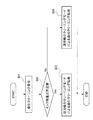
1 to 10 are views for explaining an ink jet printer in which an ink supply mechanism is configured by the liquid supply apparatus according to the first embodiment of the present invention. FIG. 1 is an external perspective view of the ink jet printer, and FIG. FIG. 3 is a perspective view of the ink jet printer with the printer cover opened, FIG. 3 is a perspective view of the ink jet printer with the printer case removed, FIG. 4 is a plan view of the ink pump unit and the regulating plate, and FIG. FIG. 6 is a sectional view showing the structure of the self-sealing unit, FIG. 7 is a block diagram for explaining the control system of the ink jet printer, and FIG. 8 is a diagram showing the remaining ink amount and the internal pressure of the ink cartridge. FIG. 9 is a graph showing the movement during suction cleaning in the ink supply mechanism of an inkjet printer. Sectional view bright, FIG. 10 is a flowchart showing the control of the suction cleaning by the control unit of the inkjet printer.
まず、本実施形態の印刷装置であるインクジェットプリンタの構造について説明する。
図1に示すように、インクジェットプリンタ1は、複数種のカラーインクを使用してロール紙の繰り出された一部にカラー印刷するものであり、プリンタ本体を覆うプリンタケース2の前面には、ロール紙カバー5及びインクカートリッジカバー7が開閉自在に設けられている。更に、プリンタケース2の前面には、電源スイッチ3と共にフィードスイッチやインジケータ等も配置されている。
First, the structure of an inkjet printer that is a printing apparatus according to the present embodiment will be described.
As shown in FIG. 1, an ink jet printer 1 uses a plurality of types of color inks to perform color printing on a part of roll paper that has been fed out. A paper cover 5 and an
ロール紙カバー5を開くと、図2に示すように、印刷される媒体であるロール紙11を収容した用紙収容部13が開放状態になって、ロール紙11の交換が可能になる。
また、インクカートリッジカバー7を開くと、カートリッジ装着部15が開放状態になり、カートリッジ装着部15へのインクカートリッジ(メインタンク)17の着脱が可能になる。
When the roll paper cover 5 is opened, as shown in FIG. 2, the paper storage unit 13 that stores the
When the
この場合、インクカートリッジカバー7を開く動作に連動して、カートリッジ装着部15の前方にインクカートリッジ17が所定距離だけ引き出される構成になっている。
In this case, the
プリンタケース2内の用紙収容部13の上方には、図3に示すように、インクジェットヘッド(ヘッド)21を搭載したキャリッジ23が設けられている。キャリッジ23は、ロール紙11の幅方向に沿って延在するガイド部材25によって用紙幅方向に移動自在に支持されると共に、ロール紙11の幅方向に延在する無端ベルト26aと無端ベルト26aを駆動するキャリッジモータ26bとによって、プラテン28の上方をロール紙11の幅方向に往復移動可能になっている。インクジェットヘッド21は、ロール紙11の繰り出された一部に対してインクを吐出して印刷処理を行う。
As shown in FIG. 3, a
図示のように、カートリッジ装着部15の上方が、往復移動するキャリッジ23の待機位置(ホームポジション)となっている。そして、この待機位置の下方には、キャリッジ23の下面に露出するインクジェットヘッド21のインクノズルを覆うキャップ27と、キャップ27を介してインクジェットヘッド21の各インクノズル内のインクを吸引廃棄するインク吸引機構(吸引機構)29とが設けられている。
As shown in the drawing, the upper portion of the
そして、インクジェットプリンタ1では、所定のタイミングあるいはユーザの操作時に、インクジェットヘッド21のインクノズル面にキャップ27を密着させてインク吸引機構29によって内部を吸引してインクノズルから増粘状態のインク及び気泡を吸引するクリーニング処理が行われる。
また、インクジェットヘッド21のインクノズルでのインクのメニスカスを形成するために、印刷処理前後あるいは定期的にインクジェットヘッド21のインクノズルから所定量のインク滴をキャップ27内に吐出するフラッシング処理を行う。
In the ink jet printer 1, at a predetermined timing or at the time of user operation, the
Further, in order to form an ink meniscus at the ink nozzles of the
さらに、インクジェットプリンタ1では、印刷休止後にホームポジションに配置させたインクジェットヘッド21のインクノズル面にキャップ27を密着させて保護し、インクノズルの詰まりを防止するキャッピングが行われる。
Further, in the inkjet printer 1, capping is performed to protect the
インクカートリッジ17は、カートリッジケース18内に複数個の図示略のカラーインクパックを収容したものである。インクカートリッジ17内の各インクパック(貯留部)は、可撓性材料からなり容量可変であって、内部にインクを貯留した状態で密封されるもので、インクカートリッジ17をカートリッジ装着部15に装着した際に、カートリッジ装着部15側に設けられた図示略のインク供給針がインクパックのインク供給口に差込接続される。カートリッジ装着部15のインク供給針には、プリンタケース2内に固定されたインク流路31が接続され、このインク流路31には、各色に分けられた可撓性のインク供給チューブ33の一端が接続されている。
The
インク供給チューブ33の他端は、キャリッジ23上に設けられた各色のインクポンプ部(補給機構)34に接続されている。各インクポンプ部34は、インクジェットヘッド21の上方に設けられており、インクジェットヘッド21に接続された自己封止ユニット36にそれぞれ接続されている。
The other end of the
キャリッジ23には、インクジェットヘッド21の他に、インクポンプ部34及び自己封止ユニット36が一体的に搭載された構成になっている。
これにより、インクカートリッジ17内の各インクパックのインクは、カートリッジ装着部15のインク供給針から、インク流路31、インク供給チューブ33、各色のインクポンプ部34及び各色の自己封止ユニット36を経て、インクジェットヘッド21の各インクノズルにそれぞれ供給されるようになっている。
In addition to the
As a result, the ink in each ink pack in the
インクポンプ部34は、プリンタ1の本体に対して移動可能なキャリッジ23が移動することによりインクカートリッジ17からインクを引き込むもので、プリンタ1の本体側には、キャリッジ23が移動することによりインクポンプ部34を動作させる図4にも示す規制板37が、キャリッジ23の待機位置への移動方向前方に配置されている。
そして、上記インクジェットプリンタ1では、インクカートリッジ17、サブタンク45、インクジェットヘッド21、キャリッジ23及びインクポンプ部34からインク供給機構(液体供給機構)が構成されている。
The
In the ink jet printer 1, the
次に、インク供給機構を構成するインクポンプ部34について、一色分の構造を例示して説明する。
図5に示すように、流路31のインクカートリッジ17側における端部には、逆止弁41が設けられ、インクカートリッジ17とインクポンプ部34との間において、逆止弁41によってインクカートリッジ17側からインクポンプ部34側へのみインクが流れるようになっている。
Next, the
As shown in FIG. 5, a
インクポンプ部34は、インクカートリッジ17からインク供給チューブ33を介してインクを引き込むサブタンク45を備えている。このサブタンク45は、上部分割体46と下部分割体47とで構成されており、これら上部分割体46と下部分割体47との間に、可撓性を有するダイヤフラムからなる可撓膜49によってその上部が覆われたインク室(液室)50を有している。この可撓膜49は、水分透過性及びガス透過性の低いブチルゴム等から形成されている。
The
このインク室50は、インク供給チューブ33に連通しかつ自己封止ユニット36側の流路42に連通しており、インクカートリッジ17からインクが供給されるとともに自己封止ユニット36側にインクを供給可能となっている。また、インク流路42の自己封止ユニット36側における端部には、逆止弁43が設けられ、インク室50と自己封止ユニット36側との間において、逆止弁43によってインク室50側から自己封止ユニット36側へのみインクが流れるようになっている。可撓膜49は、変形容易な可撓性材料からなっており、この可撓膜49の変形をともなってインク室50が容量可変となり、拡張、縮小される。インクポンプ部34には、この可撓膜49を変位させてインク室50を拡張する拡張機構52が設けられている。
The
拡張機構52は、上下方向に延在する筒状のシリンダ53と、このシリンダ53内で上下に摺動可能に嵌挿されるピストン(可動部材)54と、上部分割体46におけるシリンダ53の上方に配置された揺動軸55に揺動可能に支持された揺動アーム56と、揺動アーム56とピストン54との間に介装された引っ張りコイルバネ(弾性部)57とを有している。
The
シリンダ53は、水分透過性及びガス透過性の低いポリプロピレン等の樹脂材料からなっている。シリンダ53は、ピストン54の外径よりもわずかに大径の内径を有してピストン54の外周面を摺動可能に案内する小径内周面59が上部に形成され、下部にピストン54の外周面との間に隙間を形成する大径内周面60が形成された段差形状をなしている。
The
ピストン54は、水分透過性及びガス透過性の低いポリプロピレン等の樹脂材料から形成されている。ピストン54は、略有底筒状に形成されて、その揺動アーム56側は、揺動アーム56を配置させるため、上端から中間位置まで切り欠かれている。
The
また、ピストン54の底部より上方には、引っ張りコイルバネ57の下端を係止する係止部67が形成されている。
A locking
揺動アーム56は、揺動軸55からシリンダ53内に延出する腕部69と、揺動軸55から下方に延出する上下延出部70と、上下延出部70の腕部69とは反対側の端部から腕部69とは逆向きに延出する入力部71とを有している。腕部69の先端は鉤状とされており、この部分に引っ張りコイルバネ57の上端が係止されている。
The
可撓膜49は、上部分割体46の円環溝73に嵌合された状態で上部分割体46と下部分割体47とに挟持される円環状の厚肉のベース部74と、このベース部74の内周部から筒状をなして延出する薄肉の膜部75と、膜部75のベース部74とは反対側を閉塞させる厚肉の略円板状の固定部76とを有する一体成形品である。
The
固定部76の中央には、先細り形状の突起部77が一体成形され、この突起部77がピストン54に形成されたスリット65に圧入されて嵌合されている。この状態で固定部76がピストン54の底部に一体化され、よって可撓膜49は、ピストン54の移動により固定部76及び膜部75が変位する。
A tapered
また、インク室50を構成するシリンダ53の底部には、流路42と連通する凹部38が形成されている。
さらに、インク流路31には、吸引クリーニング時に作動されるチョーク弁39が設けられており、このチョーク弁39によってインク流路31が開閉可能とされている。
A
Further, the
図6に示すように、自己封止ユニット36は、ユニット本体81に、供給路82、中間路83及び排出路84が形成されている。そして、供給路82に形成された供給口82aに、流路42の下流側端部が接続され、排出路84に形成された排出口84aに、インクジェットヘッド21が接続されている。
As shown in FIG. 6, in the self-sealing
供給路82と中間路83とを区画する壁部85には、流入口85aが形成されており、この流入口85aで供給路82内のインクが中間路83内へ流入される。また、中間路83と排出路84とを区画する壁部86には、連通口86aが形成されており、この連通口86aで中間路83内のインクが排出路84内へ流入される。
An
中間路83内には、壁部86に支点部87が形成されており、この支点部87には、揺動棒91が揺動可能に支持されている。この揺動棒91には、その一端部に、壁部85側へ向かって屈曲する作動棒部92が一体に形成されており、この作動棒部92の先端には、壁部85に当接して流入口85aを閉鎖する閉鎖板93が形成されている。また、この閉鎖板93と壁部86との間には、圧縮バネ94が設けられ、この圧縮バネ94の付勢力によって閉鎖板93が壁部85側へ向かって付勢されている。また、揺動棒91の他端部には、壁部86側へ屈曲され、この壁部86の連通口86aに挿通された押圧棒部95が形成されている。
A
また、ユニット本体81の排出路84側の側壁81aには、開口部96が形成されている。この開口部96には、その開口縁部に、液密性及び可撓性を有するフィルム97が液密的に連結されている。このフィルム97の排出路84側における中央部分には、押圧板98が固定されている。そして、この押圧板98に、揺動棒91の押圧棒部95の先端部が当接されている。
An
また、押圧板98と壁部86との間には圧縮バネ99が取り付けられており、この圧縮バネ99の付勢力によって押圧板98が外側へ押し出されている。そして、この自己封止ユニット36では、閉鎖板93が、圧縮バネ94及び閉鎖板93に作用する圧力によって壁部85に押し付けられ、流入口85aが閉鎖される。
A
そして、自己封止ユニット36では、フィルム97によって覆われた部分の容積の減少にともない押圧板98によって揺動棒91の押圧棒部95が押圧されると、揺動棒91が支点部87による連結箇所を中心として揺動することにより、閉鎖板93が壁部85から離れる。これにより、供給路82から流入口85aを通って中間路83及び排出路84へインクが流れ込み、インクジェットヘッド21へ供給される。
In the self-sealing
そして、この自己封止ユニット36をインクジェットヘッド21の上流側に設けることにより、例えば、キャリッジ23の加減速などによって供給側におけるインクの圧力変動が発生したとしても、この圧力変動のインクジェットヘッド21への伝達が自己封止ユニット36で遮断される。
これにより、圧力変動が伝達されることによるインクジェットヘッド21での意図しないインクの吐出、インクだれまたは吐出不良によるドット抜けなどの不具合が防止される。
By providing the self-sealing
This prevents problems such as unintentional ink ejection from the
上記構造のプリンタ1において、キャリッジ23が待機位置にあるとき、揺動アーム56の入力部71がキャリッジ23外の規制板37に当接し、上下延出部70が鉛直に沿い腕部69及び入力部71が水平をなす状態とされる。このとき、引っ張りコイルバネ57の付勢力でピストン54が引き上げられる。
In the printer 1 having the above structure, when the
また、キャリッジ23が待機位置から離れてインクジェットヘッド21を印刷可能領域に位置させ、その後、この印刷可能領域内でインクジェットヘッド21がインクを吐出させて印刷を行うことで、自己封止ユニット36からインクジェットヘッド21にインクが供給され、自己封止ユニット36内が負圧になると、インク室50から流路42を介して自己封止ユニット36にインクが供給される。
Further, the
ここで、インク室50のインクが減少すると、このインクの減少により生じる負圧で、可撓膜49の膜部75を変形させながら固定部76と一体にピストン54が下降する。すると、ピストン54に引っ張りコイルバネ57を介して連結された揺動アーム56が腕部69の先端を下降させるように揺動することになり、その結果、揺動アーム56の入力部71の側方への突出量が拡大する。
Here, when the ink in the
この状態からキャリッジ23が待機位置に戻ると、キャリッジ23とともに移動する揺動アーム56が入力部71においてキャリッジ23外の規制板37に当接して、キャリッジ23が移動することにより揺動し、上下延出部70が鉛直に沿い腕部69及び入力部71が水平をなす。これにより、腕部69の先端部が上昇し、引っ張りコイルバネ57を介して連結されたピストン54がシリンダ53内を摺動して引き上げられる。
When the
この引っ張りコイルバネ57を介して行われるピストン54の移動によって、インクポンプ部34の可撓膜49の固定部76がピストン54と一体に上昇し、サブタンク45のインク室50が拡張されて容量が増大される。このように、インク室50の容量が増大すると、逆止弁41を開きながら、且つ、逆止弁43を閉じながらインクカートリッジ17からインク流路31及びインク供給チューブ33を介してインクがインク室50に吸引されることになる。
Due to the movement of the
そして、上記構造のインクジェットプリンタ1では、制御部100が、所定のタイミングで、上記のインク補給動作を行う。なお、このインク補給動作は、最大にインクを消費する印刷が行われても、少なくともインクジェットヘッド21へインクを供給可能な程度の量のインクがインク室50内に残留した状態で行われる。
And in the inkjet printer 1 of the said structure, the
図7に示すように、インクジェットプリンタ1の制御部100は、インクジェットヘッド21及びキャリッジモータ26bに制御信号を送信することにより、インクジェットヘッド21及びキャリッジモータ26bの駆動を制御し、ロール紙11への印刷処理等を実行するものである。また、制御部100には、キャリッジ23の位置情報を送信するエンコーダ103が接続されており、制御部100は、エンコーダ103からの信号によってキャリッジ23の位置を検出する。また、制御部100には、インク流路31を開閉するチョーク弁39が接続されており、制御部100によってチョーク弁39が開閉制御される。
As shown in FIG. 7, the
この制御部100は、検知手段111、演算手段(残量検出部)112、比較手段(比較部)113、記憶手段114及びCPU(設定部)115を備え、検知手段111、演算手段112及び比較手段113はCPU115によって制御される。
The
また、この制御部100には、リーダライター101が接続されている。このリーダライター101は、インクカートリッジ17に設けられたICチップ102に対して、インク情報の読み書きを行う。ICチップ102に書き込まれるインク情報としては、例えば、インク消費量、インク残量、廃インク量、使用開始日、使用装置情報などである。
A reader /
制御部100は、カートリッジ装着部15に装着されているインクカートリッジ17のICチップ102に記憶されているインク情報をリーダライター101によって読み取る。なお、装着されているインクカートリッジ17が新品であった場合は、ICチップ102に、使用開始日及び使用装置情報を書き込む。
The
また、印刷処理又はクリーニング処理が行われると、演算手段112は、印刷処理、フラッシング処理又はクリーニング処理によってインクジェットヘッド21から吐出されるインク滴のドットカウント値を求め、ドットカウント値としてICチップ102に既に記憶されているインク消費量に、求めたドットカウント値を加算してトータルのインク消費量を更新し、ICチップ102に書き込む。
Further, when the printing process or the cleaning process is performed, the
ここで、図8に示すように、インクカートリッジ17内の圧力は、インク残量が減少するに従い緩やかに減少して引っ張りコイルバネ57の付勢力Aを下回り、空に近くなると急激に低下する。
Here, as shown in FIG. 8, the pressure in the
そして、クリーニング処理時に、インクカートリッジ17のインク残量が減少して内圧が引っ張りコイルバネ57の付勢力Aを下回る領域では、吸引圧が弱くても、サブタンク45のインク室50内が十分に負圧となる。これにより、この状態であれば、図9(a)に示すように、待機位置にて、揺動アーム56の入力部71が規制板37に当接し、腕部69の先端部が上昇し、引っ張りコイルバネ57を介して連結されたピストン54が引き上げられた状態から、図9(b)に示すように、引っ張りコイルバネ57の付勢力Aに抗してピストン54が引き下ろされ、ピストン54の下端に存在する気泡Bを吸い出すことができる。
In the cleaning process, in the region where the remaining amount of ink in the
これに対して、インクカートリッジ17のインク残量が十分であり、内圧が引っ張りコイルバネ57の付勢力A以上であると、インクジェットヘッド21からのインクの吸引に伴い、インクカートリッジ17からインクが送り込まれてしまうため、サブタンク45のインク室50内の圧力が十分に下がらない。このため、ピストン54は、図9(a)に示すように、引っ張りコイルバネ57によって引き上げられた状態に維持され、気泡Bが除去されず、インクだけが吸引されてしまう。
On the other hand, when the ink remaining in the
このため、制御部100は、上記のインクカートリッジ17におけるインク残量と負圧との関係に応じたクリーニング処理の制御を行う。
なお、このインク残量と負圧との関係において、インクカートリッジ17の内圧が引っ張りコイルバネ57の付勢力Aを下回った時点のインク残量値が所定値とされて記憶手段114に記憶されている。
Therefore, the
Incidentally, in the relationship between the remaining amount of ink and the negative pressure, the remaining amount of ink when the internal pressure of the
次に、制御部100によるクリーニング処理の制御について、図10に示すフローチャートを参照して説明する。
所定のタイミングあるいはユーザの操作により、制御部100へ気泡除去のための吸引クリーニング指令が送信されると(ステップS01)、キャリッジ23が待機位置に移動する。これにより、図9(a)に示すように、キャリッジ23とともに移動する揺動アーム56が入力部71においてキャリッジ23外の規制板37に当接して揺動し、腕部69の先端部が上昇し、引っ張りコイルバネ57を介して連結されたピストン54がシリンダ53内を摺動して引き上げられる。
Next, the cleaning process control by the
When a suction cleaning command for removing bubbles is transmitted to the
次に、制御部100では、演算手段112が、インクカートリッジ17のインク残量を割り出し、比較手段113が、インクカートリッジ17のインク残量が所定値未満か否かを判断する(比較工程:ステップS02)。
ここで、前述したように、インクカートリッジ17のインク残量が減少すると、負圧が増加する。このため、インク室50を拡張してインクを引き込む際に要する負荷が大きくなり、キャリッジモータ26bの電流値が大きく増加する。したがって、インクカートリッジ17のインク残量は、検知手段111によって検出されるキャリッジモータ26bの電流値に基づき、キャリッジ23の移動に要する電流値の変化率を求めることにより、この電流値の変化率から割り出すことができる。
Next, in the
Here, as described above, when the remaining amount of ink in the
上記の比較の結果、インク残量が所定値以上の場合(ステップS02:Yes)、CPU115が、クリーニング処理の設定を強力吸引クリーニング(第1のクリーニング)モードに設定する(設定工程:ステップS03)。
As a result of the above comparison, when the ink remaining amount is equal to or greater than the predetermined value (step S02: Yes), the
そして、この強力吸引クリーニングモードに設定されると、制御部100は、強力クリーニングモードにて吸引クリーニング処理を行い、その後、吸引クリーニング制御を終了する。
具体的には、インクジェットヘッド21のインクノズル面にキャップ27を密着させた状態にて、チョーク弁39によってインク流路31を閉鎖し、インク吸引機構29によってキャップ27内を吸引してインクジェットヘッド21のインクノズルからインクを高圧の吸引圧にて吸引する。
When the strong suction cleaning mode is set, the
Specifically, in a state where the
そして、この強力吸引クリーニングモードによる吸引クリーニング処理では、チョーク弁39によってインクカートリッジ17からのインクの供給が遮断されて高圧の吸引圧にて吸引され、サブタンク45のインク室50内が十分に負圧となる。これにより、引き上げられていたピストン54が、図9(b)に示すように、引っ張りコイルバネ57の付勢力Aに抗して引き下ろされ、ピストン54の下端に溜まっていた気泡Bが、インク室50を構成するシリンダ53の底面に形成された凹部38内に送り込まれ、自己封止ユニット36に繋がる流路42から吸い出される。
In the suction cleaning process in the strong suction cleaning mode, the supply of ink from the
これに対して、インク残量が所定値未満である場合(ステップS02:No)、CPU115が、クリーニング処理の設定を通常吸引クリーニング(第2のクリーニング)モードに設定する(設定工程:ステップS04)。
On the other hand, when the ink remaining amount is less than the predetermined value (step S02: No), the
そして、この通常吸引クリーニングモードに設定されると、制御部100は、通常クリーニングモードにて吸引クリーニング処理を行い、その後、吸引クリーニング制御を終了する。
具体的には、インクジェットヘッド21のインクノズル面にキャップ27を密着させた状態にて、チョーク弁39によるインク流路31の閉鎖を行わず、インク吸引機構29によってキャップ27内を吸引してインクジェットヘッド21のインクノズルからインクを低圧の吸引圧にて吸引する。このときの吸引圧は、強力吸引クリーニングモードでの吸引圧よりも弱いもので、インクジェットヘッド21のインクノズルから増粘状態のインクを吸引する通常クリーニング処理時の吸引圧と同等とされている。
When the normal suction cleaning mode is set, the
Specifically, in a state where the
そして、この通常吸引クリーニングモードによる吸引クリーニング処理では、インクカートリッジ17のインク残量が減少して内圧が引っ張りコイルバネ57の付勢力Aを下回っていることから、吸引圧が弱くても、サブタンク45のインク室50内が十分に負圧となる。これにより、引き上げられていたピストン54が、図9(b)に示すように、引っ張りコイルバネ57の付勢力Aに抗して引き下ろされ、ピストン54の下端に溜まっていた気泡Bが、インク室50を構成するシリンダ53の底面に形成された凹部38内に送り込まれ、自己封止ユニット36に繋がる流路42から吸い出される。
In the suction cleaning process in the normal suction cleaning mode, the remaining amount of ink in the
以上、説明したように、本実施形態によれば、インクカートリッジ17は密封された容量可変のインクパックにインクが貯留されたものであるため、インクカートリッジ17のインク残量が減少することでクリーニング時におけるインク室50の収縮に要する吸引圧が減少する。そして、インクカートリッジ17のインク残量が所定値以上の場合に高圧の吸引圧にて吸引クリーニングを行う第1クリーニングモードである強力吸引クリーニングモードとし、インクカートリッジ17のインク残量が所定値未満の場合に第1クリーニングよりも低圧の吸引圧にて吸引クリーニングを行う第2クリーニングモードである通常吸引クリーニングモードとする。これにより、インクの消耗量が多い高圧での吸引クリーニングを少なくすることができ、吸引クリーニングによるインクの無駄を極力抑えることができる。
As described above, according to the present embodiment, since the
つまり、吸引クリーニングに伴うインクの無駄を極力抑えつつ良好に吸引クリーニングを行ってインク室50内の気泡Bを除去し、良好なインク吐出動作を維持することができ、効率良く高品質に印刷することができ、しかも、簡易な構造で小型化及び低コスト化を図ることができる。
That is, it is possible to remove the bubbles B in the
また、サブタンク45のインク室50には、インクジェットヘッド21へのインクの供給路である流路42と連通する凹部38が形成されているので、吸引クリーニングによってインク室50を収縮させた際に、インク室50内の気泡Bを凹部38に導いて集め、この凹部38から流路42へ引き込ませて排出させることができる。
In addition, since the
さらに、インクカートリッジ17におけるインクの残量によって変化するキャリッジ23の移動に要する電流値からインクカートリッジ17のインク残量を求めるので、インクカートリッジ17のインク残量を正確に求め、吸引クリーニングのモード切り替えを円滑に行うことができる。
Further, since the ink remaining amount of the
なお、上記実施形態において、演算手段112が算出したインクカートリッジ17内のインク残量に応じて強力吸引クリーニングモードでの吸引クリーニング処理における吸引圧を調整しても良い。
具体的には、吸引クリーニング処理の設定を強力吸引クリーニング(第1のクリーニング)モードに設定した後(設定工程:ステップS03)、算出したインクカートリッジ17のインク残量に応じ、強力吸引クリーニングモードでの吸引クリーニング処理における吸引圧を必要最小限に設定する。なお、この吸引圧の調整は、インク吸引機構29による吸引時間によって容易に調整することができる。
そして、このように、インクカートリッジ17のインク残量に応じて吸引圧を調整して最小限に抑えることにより、吸引クリーニングによるインクの無駄をさらに抑えることができる。
In the above embodiment, the suction pressure in the suction cleaning process in the strong suction cleaning mode may be adjusted according to the ink remaining amount in the
Specifically, after setting the suction cleaning process to the strong suction cleaning (first cleaning) mode (setting step: step S03), the strong suction cleaning mode is set according to the calculated ink remaining amount of the
In this way, by adjusting the suction pressure according to the remaining amount of ink in the
また、上記実施形態では、キャリッジ23の移動に要する電流値からインクカートリッジ17のインク残量を求めたが、このインクカートリッジ17のインク残量は、インクジェットヘッド21からのインクの吐出量から求めても良い。
具体的には、ICチップ102のインク情報と、印刷処理及びフラッシングによってインクジェットヘッド21から吐出されて消費したインク量とに基づいて、演算手段112がインクカートリッジ17のインク残量を求める。
そして、このようにインクジェットヘッド21からのインクの吐出量からインクカートリッジ17のインク残量を正確に求めることにより、吸引クリーニングのモード切り替えを円滑に行うことができる。
In the above embodiment, the ink remaining amount of the
Specifically, based on the ink information of the
Then, by accurately determining the remaining amount of ink in the
また、本発明に係る液体供給装置は、上記実施形態で例示したインクジェット式のプリンタをはじめとして、液晶ディスプレイ等のカラーフィルタの製造に用いられる色材吐出ヘッド、有機ELディスプレイ、FED(面発光ディスプレイ)等の電極形成に用いられる電極材吐出ヘッド、バイオチップ製造に用いられる生体有機物吐出ヘッド等の液体を吐出する液体吐出ヘッドに液体を供給する液体供給装置、精密ピペットとしての試料吐出装置への液体供給装置等にも適用できる。
また、液体の概念にはジェル状のもの、粘性の高いもの、固形物を溶媒に混合させたもの、も含み、さらにインクの概念には水性インクも油性インクも含む。
The liquid supply apparatus according to the present invention includes a color material discharge head, an organic EL display, and an FED (surface emitting display) used for manufacturing a color filter such as a liquid crystal display, including the ink jet printer exemplified in the above embodiment. ) Electrode material discharge head used for electrode formation, bioorganic discharge head used for biochip manufacturing, etc., liquid supply device for supplying liquid to the liquid discharge head, and sample discharge device as a precision pipette It can also be applied to a liquid supply device or the like.
Further, the concept of liquid includes gel-like, highly viscous, and solid mixed with a solvent, and the concept of ink includes water-based ink and oil-based ink.
1…インクジェットプリンタ(印刷装置、液体供給装置)、17…インクカートリッジ(メインタンク)、21…インクジェットヘッド(ヘッド)、23…キャリッジ、29…インク吸引機構(吸引機構)、37…規制板(規制部)、38…凹部、42…流路、45…サブタンク、50…インク室(液室)、52…拡張機構、54…ピストン(可動部材)、112…演算手段(残量検出部)、113…比較手段(比較部)、115…CPU(設定部)。 DESCRIPTION OF SYMBOLS 1 ... Inkjet printer (printing apparatus, liquid supply apparatus), 17 ... Ink cartridge (main tank), 21 ... Inkjet head (head), 23 ... Carriage, 29 ... Ink suction mechanism (suction mechanism), 37 ... Restriction plate (restriction) Part), 38 ... concave part, 42 ... flow path, 45 ... sub tank, 50 ... ink chamber (liquid chamber), 52 ... expansion mechanism, 54 ... piston (movable member), 112 ... calculation means (remaining amount detection part), 113 ... comparison means (comparison unit), 115 ... CPU (setting unit).
Claims (6)
前記メインタンクから液体が補給される液室を有するサブタンクと、
前記サブタンクから供給される液体を吐出するヘッドと、
前記ヘッド及び前記サブタンクが搭載されて移動可能なキャリッジと、
前記キャリッジが移動することにより、引っ張りコイルバネを介して連結された可動部材が前記引っ張りコイルバネの付勢力で引き上げられ、前記可動部材の底部に一体化された可撓膜を変位させることにより前記液室を拡張させて前記メインタンクから液体を引き込む拡張機構と、
前記ヘッドに形成された液体吐出用のノズルから液体を吸引して前記ノズルのクリーニングを行う吸引機構と、を有する液体供給装置であって、
前記メインタンクの液体残量が減少すると前記液室内の負圧が増加して、前記液室を拡張して液体を引き込む際に要する負荷が大きくなって前記キャリッジの移動に要する電流値が増加することに基づき、前記電流値を検出して前記キャリッジの移動に要する電流値の変化率を求め、該電流値の変化率から前記メインタンクの液体残量を検出する残量検出部と、
前記メインタンクの液体残量と所定値とを比較する比較部と、
前記ノズルのクリーニングを行う第1クリーニングモードと、前記第1クリーニングモードよりも低圧の吸引圧で行う第2クリーニングモードとに設定する設定部と、を備え、
前記比較部が前記メインタンクの液体残量と前記所定値とを比較した結果、前記メインタンクの液体残量が前記所定値以上である場合には前記ノズルのクリーニングを前記第1クリーニングモードで行い、前記所定値未満である場合には前記ノズルのクリーニングを前記第2クリーニングモードで行うことを特徴とする液体供給装置。 A main tank in which liquid is stored in a plurality of storage units;
A sub tank having a liquid chamber in which liquid is replenished from the main tank;
A head for discharging liquid supplied from the sub-tank;
A carriage on which the head and the sub tank are mounted and movable;
When the carriage moves, the movable member connected via the tension coil spring is pulled up by the urging force of the tension coil spring, and the flexible film integrated with the bottom of the movable member is displaced to displace the liquid chamber. An expansion mechanism that expands and draws liquid from the main tank,
A liquid supply device having a suction mechanism for cleaning the nozzle by sucking the liquid from a liquid discharge nozzle formed on the head,
When the remaining amount of liquid in the main tank decreases, the negative pressure in the liquid chamber increases, so that the load required to expand the liquid chamber and draw liquid increases, and the current value required to move the carriage increases. Based on that, the current value is detected to determine a change rate of the current value required for the movement of the carriage, and a remaining amount detection unit that detects the remaining amount of liquid in the main tank from the change rate of the current value ;
A comparison unit that compares the remaining amount of liquid in the main tank with a predetermined value;
A setting unit configured to set a first cleaning mode for cleaning the nozzle and a second cleaning mode performed at a suction pressure lower than that of the first cleaning mode,
When the comparison unit compares the remaining amount of liquid in the main tank with the predetermined value, if the remaining amount of liquid in the main tank is equal to or greater than the predetermined value, the nozzle is cleaned in the first cleaning mode. The liquid supply apparatus according to claim 1, wherein the nozzle is cleaned in the second cleaning mode when the value is less than the predetermined value.
前記サブタンクの前記液室には、前記ヘッドへの液体の流路と連通する凹部が形成されていることを特徴とする液体供給装置。 The liquid supply apparatus according to claim 1,
The liquid supply device according to claim 1, wherein the liquid chamber of the sub-tank is formed with a recess communicating with a liquid flow path to the head.
前記第1クリーニングモードでのクリーニング時の吸引圧が、前記メインタンクの液体残量に応じて変化することを特徴とする液体供給装置。 The liquid supply apparatus according to claim 1 or 2,
The liquid supply apparatus according to claim 1, wherein a suction pressure at the time of cleaning in the first cleaning mode changes according to a remaining amount of liquid in the main tank.
前記ヘッドへインクを供給する装置として、請求項1から3の何れか一項に記載の液体供給装置を備えていることを特徴とする印刷装置。A printing apparatus comprising the liquid supply apparatus according to claim 1 as an apparatus for supplying ink to the head.
前記メインタンクから液体が補給される液室を有するサブタンクと、A sub tank having a liquid chamber in which liquid is replenished from the main tank;
前記サブタンクから供給される液体を吐出するヘッドと、A head for discharging liquid supplied from the sub-tank;
前記ヘッド及び前記サブタンクが搭載されて移動可能なキャリッジと、A carriage on which the head and the sub tank are mounted and movable;
前記キャリッジが移動することにより、引っ張りコイルバネを介して連結された可動部材が前記引っ張りコイルバネの付勢力で引き上げられ、該可動部材の底部に一体化された可撓膜を変位させることにより前記液室を拡張させて前記メインタンクから液体を引き込む拡張機構と、When the carriage moves, the movable member connected via the tension coil spring is pulled up by the urging force of the tension coil spring, and the flexible film integrated with the bottom of the movable member is displaced to displace the liquid chamber. An expansion mechanism that expands and draws liquid from the main tank,
前記ヘッドに形成された液体吐出用のノズルから液体を吸引して前記ノズルのクリーニングを行う吸引機構と、を有する液体供給装置の制御方法であって、A liquid supply device control method comprising: a suction mechanism that sucks liquid from a liquid discharge nozzle formed on the head and cleans the nozzle;
前記メインタンクの液体残量が減少すると前記液室内の負圧が増加して、前記液室を拡張して液体を引き込む際に要する負荷が大きくなって前記キャリッジの移動に要する電流値が増加することに基づき、前記電流値を検出して前記キャリッジの移動に要する電流値の変化率を求め、該電流値の変化率から前記メインタンクの液体残量を検出する工程と、When the remaining amount of liquid in the main tank decreases, the negative pressure in the liquid chamber increases, so that the load required to expand the liquid chamber and draw liquid increases, and the current value required to move the carriage increases. A step of detecting the current value to obtain a rate of change of the current value required for movement of the carriage, and detecting a remaining amount of liquid in the main tank from the rate of change of the current value;
前記メインタンクの液体残量と所定値とを比較する比較工程と、A comparison step of comparing the remaining amount of liquid in the main tank with a predetermined value;
前記メインタンクの液体残量が所定値以上である場合に前記吸引機構による前記クリーニングを第1クリーニングモードとし、前記メインタンクの液体残量が所定値未満である場合に前記吸引機構による前記クリーニングを前記第1クリーニングモードよりも低圧の吸引圧にて行う第2クリーニングモードとする設定工程と、を含むことを特徴とする液体供給装置の制御方法。The cleaning by the suction mechanism is set to a first cleaning mode when the remaining amount of liquid in the main tank is greater than or equal to a predetermined value, and the cleaning by the suction mechanism is performed when the remaining amount of liquid in the main tank is less than a predetermined value. And a setting step for setting the second cleaning mode to be performed at a suction pressure lower than that in the first cleaning mode.
前記第1クリーニングモードでのクリーニング時の吸引圧を、前記メインタンクの液体残量に応じて変化させることを特徴とする液体供給装置の制御方法。A method for controlling a liquid supply apparatus, wherein a suction pressure during cleaning in the first cleaning mode is changed according to a remaining amount of liquid in the main tank.
Priority Applications (2)
| Application Number | Priority Date | Filing Date | Title |
|---|---|---|---|
| JP2008283147A JP5298780B2 (en) | 2008-11-04 | 2008-11-04 | Liquid supply apparatus, printing apparatus, and control method of liquid supply apparatus |
| US12/611,404 US8348364B2 (en) | 2008-11-04 | 2009-11-03 | Fluid supply device, printing device, and method of cleaning a printing device |
Applications Claiming Priority (1)
| Application Number | Priority Date | Filing Date | Title |
|---|---|---|---|
| JP2008283147A JP5298780B2 (en) | 2008-11-04 | 2008-11-04 | Liquid supply apparatus, printing apparatus, and control method of liquid supply apparatus |
Publications (3)
| Publication Number | Publication Date |
|---|---|
| JP2010110913A JP2010110913A (en) | 2010-05-20 |
| JP2010110913A5 JP2010110913A5 (en) | 2011-12-22 |
| JP5298780B2 true JP5298780B2 (en) | 2013-09-25 |
Family
ID=42130837
Family Applications (1)
| Application Number | Title | Priority Date | Filing Date |
|---|---|---|---|
| JP2008283147A Expired - Fee Related JP5298780B2 (en) | 2008-11-04 | 2008-11-04 | Liquid supply apparatus, printing apparatus, and control method of liquid supply apparatus |
Country Status (2)
| Country | Link |
|---|---|
| US (1) | US8348364B2 (en) |
| JP (1) | JP5298780B2 (en) |
Families Citing this family (10)
| Publication number | Priority date | Publication date | Assignee | Title |
|---|---|---|---|---|
| JP5703721B2 (en) * | 2010-12-02 | 2015-04-22 | 株式会社リコー | Image forming apparatus |
| US9102159B2 (en) * | 2013-09-13 | 2015-08-11 | Ricoh Company, Ltd. | Liquid supply device and image forming apparatus |
| JP2015080878A (en) * | 2013-10-22 | 2015-04-27 | 株式会社リコー | Image formation device |
| JP6961916B2 (en) * | 2016-09-09 | 2021-11-05 | ブラザー工業株式会社 | Inkjet printer |
| JP6950439B2 (en) * | 2017-10-10 | 2021-10-13 | ブラザー工業株式会社 | Liquid drainer |
| US11305548B2 (en) | 2017-10-20 | 2022-04-19 | Hewlett-Packard Development Company, L.P. | Cap seal and valve sequencing |
| US11046102B2 (en) | 2017-10-20 | 2021-06-29 | Hewlett-Packard Development Company, L.P. | Ink tank cap and valve linkage |
| US20190323625A1 (en) * | 2018-04-23 | 2019-10-24 | Rain Bird Corporation | Valve With Reinforcement Ports And Manually Removable Scrubber |
| JP7242323B2 (en) * | 2019-02-06 | 2023-03-20 | キヤノン株式会社 | PRESSURE CONTROL UNIT AND LIQUID EJECTION APPARATUS HAVING PRESSURE CONTROL UNIT |
| JP2022129492A (en) * | 2021-02-25 | 2022-09-06 | ブラザー工業株式会社 | printer |
Family Cites Families (20)
| Publication number | Priority date | Publication date | Assignee | Title |
|---|---|---|---|---|
| CA2059198C (en) * | 1991-01-11 | 1997-12-16 | Kazuyoshi Takahashi | Ink jet recording apparatus |
| JPH0825651A (en) * | 1994-07-13 | 1996-01-30 | Canon Inc | Ink suction recovering method for recording head |
| JP3484869B2 (en) * | 1996-04-16 | 2004-01-06 | セイコーエプソン株式会社 | Ink jet recording device |
| JPH09300645A (en) | 1996-05-10 | 1997-11-25 | Oki Data:Kk | Ink-jet device |
| JP3487331B2 (en) * | 1997-11-13 | 2004-01-19 | セイコーエプソン株式会社 | Ink jet recording device |
| US6481824B1 (en) * | 1998-01-30 | 2002-11-19 | Seiko Epson Corporation | Ink jet recording apparatus and recording head cleaning control method thereon |
| DE19947033A1 (en) * | 1999-09-30 | 2001-04-05 | Siemens Ag | Optical fiber and fiber optic isolator |
| ATE269788T1 (en) * | 1999-11-05 | 2004-07-15 | Seiko Epson Corp | INKJET RECORDING APPARATUS |
| EP1142713B9 (en) | 1999-11-05 | 2010-07-21 | Seiko Epson Corporation | Inkjet type recording device and method of supplying ink to sub-tank by the same device, and method of checking amount of ink supplied to sub-tank by the same device |
| JP2001270133A (en) | 2000-01-20 | 2001-10-02 | Seiko Epson Corp | Ink jet recorder |
| EP1916114A1 (en) * | 2000-01-21 | 2008-04-30 | Seiko Epson Corporation | Ink cartridge, and ink-jet recording apparatus using the same |
| WO2001053104A1 (en) * | 2000-01-21 | 2001-07-26 | Seiko Epson Corporation | Ink cartridge for recording device and ink jet recording device |
| JP2002154223A (en) * | 2000-11-17 | 2002-05-28 | Seiko Epson Corp | Liquid consumption state detector |
| JP4320541B2 (en) * | 2001-12-17 | 2009-08-26 | ブラザー工業株式会社 | Inkjet recording device |
| US6786566B2 (en) * | 2001-12-17 | 2004-09-07 | Brother Kogyo Kabushiki Kaisha | Ink jet recording apparatus |
| WO2003089246A1 (en) * | 2002-04-22 | 2003-10-30 | Seiko Epson Corporation | Method of cleaning print head |
| JP2005059304A (en) | 2003-08-08 | 2005-03-10 | Canon Inc | Inkjet recording apparatus and control method therefor |
| JP2007160639A (en) | 2005-12-12 | 2007-06-28 | Seiko Epson Corp | Ink feeding mechanism and recorder equipped with ink feeding mechanism |
| JP4809178B2 (en) * | 2006-09-29 | 2011-11-09 | 富士フイルム株式会社 | Liquid ejection apparatus and liquid supply method |
| JP4962041B2 (en) * | 2007-02-22 | 2012-06-27 | セイコーエプソン株式会社 | Cleaning apparatus, fluid ejecting apparatus and cleaning method in fluid ejecting apparatus |
-
2008
- 2008-11-04 JP JP2008283147A patent/JP5298780B2/en not_active Expired - Fee Related
-
2009
- 2009-11-03 US US12/611,404 patent/US8348364B2/en active Active
Also Published As
| Publication number | Publication date |
|---|---|
| US8348364B2 (en) | 2013-01-08 |
| JP2010110913A (en) | 2010-05-20 |
| US20100110119A1 (en) | 2010-05-06 |
Similar Documents
| Publication | Publication Date | Title |
|---|---|---|
| JP5298780B2 (en) | Liquid supply apparatus, printing apparatus, and control method of liquid supply apparatus | |
| JP5316311B2 (en) | Liquid supply apparatus, printing apparatus, and control method of liquid supply apparatus | |
| JP5504700B2 (en) | Liquid ejection device | |
| JP5332431B2 (en) | Liquid supply apparatus, printing apparatus, and control method of liquid supply apparatus | |
| JP2010228237A (en) | Liquid feeding apparatus and liquid jetting apparatus | |
| JP2007160639A (en) | Ink feeding mechanism and recorder equipped with ink feeding mechanism | |
| JP2009126098A (en) | Liquid feeding device and its controlling method | |
| JP5131046B2 (en) | Liquid supply apparatus and printing apparatus | |
| US8590994B2 (en) | Liquid ejecting device, printing apparatus and liquid supplying method | |
| JP2010069845A (en) | Liquid feeding apparatus, printer, and controlling method for liquid feeding apparatus | |
| JP2010120296A (en) | Liquid jet apparatus | |
| JP2010069846A (en) | Liquid feeding device, and printing device | |
| US11813875B2 (en) | Liquid ejecting system and liquid storage mechanism | |
| JP5187026B2 (en) | Liquid supply apparatus and printing apparatus | |
| JP2010000627A (en) | Liquid supplying device and printer | |
| JP2009292121A (en) | Inkjet recording apparatus | |
| JP2007160638A (en) | Ink supply mechanism, recorder and control method of ink supply mechanism | |
| JP2009126106A (en) | Liquid feeding device | |
| JP2009173002A (en) | Liquid supply device, liquid ejecting device and method for supplying liquid |
Legal Events
| Date | Code | Title | Description |
|---|---|---|---|
| A521 | Request for written amendment filed |
Free format text: JAPANESE INTERMEDIATE CODE: A523 Effective date: 20111102 |
|
| A621 | Written request for application examination |
Free format text: JAPANESE INTERMEDIATE CODE: A621 Effective date: 20111102 |
|
| RD02 | Notification of acceptance of power of attorney |
Free format text: JAPANESE INTERMEDIATE CODE: A7422 Effective date: 20120816 |
|
| A977 | Report on retrieval |
Free format text: JAPANESE INTERMEDIATE CODE: A971007 Effective date: 20121004 |
|
| A131 | Notification of reasons for refusal |
Free format text: JAPANESE INTERMEDIATE CODE: A131 Effective date: 20121016 |
|
| A521 | Request for written amendment filed |
Free format text: JAPANESE INTERMEDIATE CODE: A523 Effective date: 20121211 |
|
| TRDD | Decision of grant or rejection written | ||
| A01 | Written decision to grant a patent or to grant a registration (utility model) |
Free format text: JAPANESE INTERMEDIATE CODE: A01 Effective date: 20130521 |
|
| A61 | First payment of annual fees (during grant procedure) |
Free format text: JAPANESE INTERMEDIATE CODE: A61 Effective date: 20130603 |
|
| R150 | Certificate of patent or registration of utility model |
Ref document number: 5298780 Country of ref document: JP Free format text: JAPANESE INTERMEDIATE CODE: R150 Free format text: JAPANESE INTERMEDIATE CODE: R150 |
|
| S531 | Written request for registration of change of domicile |
Free format text: JAPANESE INTERMEDIATE CODE: R313531 |
|
| R350 | Written notification of registration of transfer |
Free format text: JAPANESE INTERMEDIATE CODE: R350 |
|
| LAPS | Cancellation because of no payment of annual fees |