US20110317841A1 - Method and device for optimizing audio quality - Google Patents
Method and device for optimizing audio quality Download PDFInfo
- Publication number
- US20110317841A1 US20110317841A1 US12/824,130 US82413010A US2011317841A1 US 20110317841 A1 US20110317841 A1 US 20110317841A1 US 82413010 A US82413010 A US 82413010A US 2011317841 A1 US2011317841 A1 US 2011317841A1
- Authority
- US
- United States
- Prior art keywords
- phase
- signal
- product
- dynamically
- gain
- Prior art date
- Legal status (The legal status is an assumption and is not a legal conclusion. Google has not performed a legal analysis and makes no representation as to the accuracy of the status listed.)
- Abandoned
Links
Images



Classifications
-
- H—ELECTRICITY
- H03—ELECTRONIC CIRCUITRY
- H03G—CONTROL OF AMPLIFICATION
- H03G9/00—Combinations of two or more types of control, e.g. gain control and tone control
- H03G9/02—Combinations of two or more types of control, e.g. gain control and tone control in untuned amplifiers
- H03G9/025—Combinations of two or more types of control, e.g. gain control and tone control in untuned amplifiers frequency-dependent volume compression or expansion, e.g. multiple-band systems
-
- H—ELECTRICITY
- H03—ELECTRONIC CIRCUITRY
- H03G—CONTROL OF AMPLIFICATION
- H03G5/00—Tone control or bandwidth control in amplifiers
- H03G5/16—Automatic control
- H03G5/165—Equalizers; Volume or gain control in limited frequency bands
Definitions
- This invention relates to a method and device for optimizing an audio source.
- Audio systems currently available including those claimed to possess high fidelity features (or Hi-Fi, referring to reproduction of sound or images with minimal noise and distortion), fail to provide the listener with a realism experience, i.e., for the listener to feel personally situated in the original sound field.
- Conventional attempts at enhancing audio reproduction quality have included use of a “static” form of sound enhancement, namely, improving certain parameters, such as amplitude or frequencies, based on predetermined settings. Such techniques are disclosed in, for example, U.S. Patent Publication No. 2008/0008324, assigned to Creative Technology Ltd.
- phase shifts and/or distortions that occur during the audio recording and transmission process.
- those techniques result in a deterioration of phase shifts and cause distortions due to their inability to automatically adjust parameter settings.
- These conventional techniques are thus unlikely to minimize noise and disharmony generated in signal processing, such as square wave phenomena, i.e., non-sinusoidal waveform, typically sounding hollow or distorted that often results in ear fatigue. Accordingly, such techniques are incapable of optimizing audio quality by enhancing acoustic accuracy.
- Still other conventional sound processing techniques such as compression formats MPEG-1 Audio Layer 3 (MP3) or Windows Media Audio (WMA) suffer from loss of sound quality from the original audio source resulting from undergoing the conversion process to a compact file. Compressing or compacting methods in existence today inevitably result in phase and frequency anomalies. Furthermore, such conventional techniques suffer from other deficiencies, such as the inability of the compressed files to be reconstructed to their original sonic quality and permanent loss of the fidelity and accuracy for certain frequencies of the original sound resulting from compression. Other deficiencies associated with these techniques include destructive effects, which often occur during the compressing process, with no conventional measure available to reverse or improve the audio parameters while minimizing the file size or transmission channel bandwidth.
- MP3 MPEG-1 Audio Layer 3
- WMA Windows Media Audio
- the inventive audio-enhancing module of the present invention is capable of dynamically enhancing the quality in the audio output by modifying the parameters thereof in response to various input signals, thereby minimizing disharmony and distortion noise to create the interacting, realism-imparting sound fields.
- the present invention provides the user with full control over the resulting sound from the audio-enhancing module, thereby “dynamically” changing various parameters of the audio input to convert it into the desirable output. Further, the present invention is capable of addressing the fatigue and hearing loss defects that result from the conventional technologies, to optimize the output quality of the audio source.
- the present invention is directed to a method and module for enhancement and optimization of audio quality. According to an aspect of the present invention, control information and an initial signal from an audio source are received and a control signal is generated based on the control information and the initial signal from the audio source.
- the control information can include, for example, Attack, Release, Length and Gain.
- Attack determines the speed at which the audio-enhancing module starts to react. Release determines the duration of stop before the Attack becomes active. Gain determines the amplitude of the output signal in dB units. Length adjusts the amount of audio data to be processed in one batch; According to its value, the audio-enhancing module determines to process a larger or smaller length of data at one time.
- the phase of the initial signal is subsequently dynamically shifted in response to the control signal.
- the control signal determines the magnitude of the dynamic phase shift in proportion thereto within a range, in both positive and negative directions.
- the amplitude of the signal is dynamically modified according to the gain control information.
- the signal that is being processed by the inventive method is one of the dual stereo signals derived from an audio signal of the audio source; and, following the processing, the two signals are blended into one.
- the dynamically phase-shifted signal is mixed with other dynamically phase-shifted signals to make the output signal more harmonic and pleasant.
- This control is dynamic, not static, in its operation and is constantly being changed according to the initial signal in both positive and negative directions.
- the post-processed signal can be flipped in phase by 180°to cancel out some of the frequencies in the combined signal.
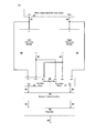
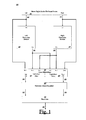
- FIG. 1 illustrates an exemplary embodiment of the Audio-Enhancing Module according to the present invention.
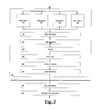
- FIG. 2 depicts various components integrated in the Left Processing Module embodying the present invention.
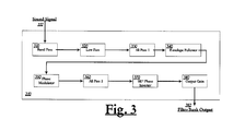
- FIG. 3 illustrates an embodiment of the Filter Bank according to the present invention.
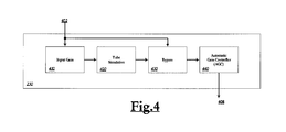
- FIG. 4 is a block diagram of the Tube Simulator as preferably embodied according to the present invention.
- FIG. 5 is a block diagram of the Sub Bass Enhancer according to the invention disclosed herein.
- FIG. 6 is a block diagram showing various inputs being mixed in the Left Mono Mixer.
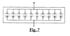
- FIG. 7 is a block diagram of the Harmonic Scripte Equalizer as preferably embodied in the current invention.
- FIG. 8 is a block diagram of an exemplary architecture 800 that the present invention can be implemented upon.
- FIG. 1 illustrates an exemplary embodiment of the Audio-Enhancing Module 100 according to the present invention.
- the Audio-Enhancing Module 100 is advantageously implemented in a software process that runs on an information processing system such as a computer (such as desktop or laptop), pocket PC, personal digital assistants (PDA), mobile devices, and the like.
- the Audio Source 110 of the Audio-Enhancing Module 100 can be either analog or digital signal.
- the Audio Source 110 is saved in the hard drive or memory of the computer or similar devices to be accessed and processed by the Audio-Enhancing Module 100 . In other implementations, the Audio Source 110 is directly sent to the Audio-Enhancing Module 100 for processing.
- the Audio Source 110 is not already in the form of stereo, it is advantageously converted into two Stereo Signals 112 , 114 upon entering the Audio-Enhancing Module 100 , which subsequently sends the two Stereo Signals 112 , 114 to Left Processing Module 188 and Right Processing Module 199 , respectively.
- the two Processing Modules 188 , 199 are preferably identical and each generate a control signal 182 , 192 based on control information such as Attack, Release, Length and Gain, which is described in further details below.
- the input signal of the Left Processing Module 188 (the Stereo Signal 112 ) is blended in Cross Blend Mixer 120 with the output signal of the Left Processing Module 188 (the Left Output 182 ) and the output signal from the Right Processing Module 199 (the Right Output 192 ) to create signal interaction and realism effects.
- the Cross Blend Mixer 120 consists of Left Mono Mixer 125 and Right Mono Mixer 127 , which respectively handle the signals on the left side and right side, as shown in FIG. 1 .
- the blending process of the Cross Blend Mixer 120 addresses the phase cancellation and reinforcement issues that are likely to have occurred in the Processing Modules 188 , 199 .
- the Output Signals 122 , 124 of the Left Mono Mixer 125 and Right Mono Mixer 127 are corrected in frequencies by Harmonic Scripte Equalizer 130 to create harmonic effects.
- the Harmonic Scripte Equalizer 130 advantageously raises or lowers a range of frequencies symmetrically centering the central frequency of the Output Signals 132 , 134 .
- the Final Gain Control 140 component adjusts Output Signals 132 , 134 , by changing the gain up or down to generate the final output 142 of the Audio-Enhancing Module 100 for receiving by apparatuses such as sound cards, amplifier, speakers, and the like.
- Table 1 provides an exemplary parameter setting used in the Final Gain Control 140 of the Audio-Enhancing Module 100 that applies to the generic “Rock & Roll” genre:
- FIG. 2 depicts various components integrated in the Left Processing Module 188 , which is a mirror diagram of the Right Processing Module 199 .
- the Left Processing Module 188 preferably includes four Filter Banks 210 , four Filter Bank Meters 220 , one Tube Simulator 230 , one Limiter 240 , one Stereo Gain 250 , one Sub Bass Enhancer 260 , and one Static Delay Filter 270 .
- the four Filter Banks 210 are identical in structure and functions to control their output in a consistent fashion.
- the Filter Banks 210 are each dedicated to process a specific and different frequency range, for example, bass, mid-bass, treble, or high-treble.
- Each Filter Bank 210 works dynamically, i.e., monitoring the amplitude, phase and frequency of the received Stereo Signal 112 in respect to its designated frequency range.
- each Filter Bank 210 encompasses a Band Pass Filter 310 , a Low Pass Filter 320 , an All Pass Filter ( 1 ) 330 , an Envelope Follower 340 , a Phase Modulator 350 , an All Pass Filter ( 2 ) 360 , a Phase Inverter 370 , and an Output Gain 380 .
- the Band Pass Filter 310 receives the Stereo Signal 112 and controls frequency and bandwidth.
- the Band Pass Filter 310 allows only frequencies between two specific points to pass, thereby filtering noises outside of the chosen parameters of points.
- the bandwidth of the Band Pass Filter 310 is the frequency difference between the upper and lower cutoff points.
- the same effect that results from the Band Pass Filter 310 may also be created by combining a low pass filter with a high-pass filter.
- the specific frequency parameters or points can be either selected by a user via the user interface of the Audio-Enhancing Module 100 or predetermined by default thereof.
- the Low Pass Filter 320 receives the Stereo Signal 112 from the Band Pass Filter 310 and controls frequency only; the Low Pass Filter 320 blocks frequencies above a specific point while allowing frequencies below that parameter or point to pass through.
- the specific frequency parameter or point can be either selected by a user via the user interface of the Audio-Enhancing Module 100 or predetermined by default thereof.
- the All Pass Filter ( 1 ) 330 passes all frequencies equally, while changing the phase relationship among various frequencies of the Stereo Signal 112 , which is being processed in the Filter Bank 210 . This process compensates the Stereo Signal 112 for undesired phase that has occurred in the Left Processing Module 188 , which could cause “quadrature” between the input and output signals, i.e., a quarter wavelength of delay there between.
- the All Pass Filter ( 2 ) 360 structures and functions similarly to the All Pass Filter ( 1 ) 330 .
- the Envelope follower 340 receives the Stereo Signal 122 from the All Pass Filter ( 1 ) 330 and controls Attack, Release, Length and Gain parameters.
- an envelope follower is implemented on an electronic circuit and converts an original signal to its “envelope shape” as the output.
- a capacitor in the electronic circuit for example, accumulates charge when the incoming amplitudes are rising.
- a resistor therein for example, discharges when the incoming amplitudes are abating.
- Attack determines the speed at which the Envelope follower 340 starts to react. When the Attack is set high, the Envelope Follower 340 is more sensitive and starts in an instant; while the Attack is set low, the Envelope Follower 340 is less sensitive, thereby increasing an envelope slower depending on the level of the Attack.
- Release determines the duration of stop before the Attack becomes active. More specifically, setting the Release high renders the duration long, while setting the release low renders the duration short.
- Gain determines the output amplitude in dB of the Envelope follower 340 .
- Gain is set at a high value, the output amplitude is increased by a higher ratio or scale.
- Gain is set at a low value, the output amplitude is increased by a lower ratio or scale.
- Length adjusts the amount of audio data to be processed in one batch. According to the value of Length, the audio-enhancing module determines to process a larger or smaller chunk of data at one time.
- the foregoing four parameters can be determined based on user selections through the user interface; alternatively, the parameters can be pre-defined in the Audio-Enhancing Module 100 .
- the Phase Modulator 350 receives the Control Signal 182 that has been processed and output by the Envelope follower 340 ; and is driven by the Gain amount set by the Envelope follower 340 .
- the Phase Modulator 350 increases or decreases an amount of phase shift dynamically in the Control Signal 182 passing therethrough. More specifically, the Phase Modulator 350 changes the phase angle of the envelope of the Control Signal 182 , in direct proportion thereto.
- the Filter Bank 210 includes the Phase Inverter 360 , which can be turned on and off. At the “on” status, the Phase Inverter 360 flips the Control Signal 182 in phase by 180 degree, in effect reversing the overall phase of the modification that has been done to the Control Signal 182 .
- the Filter Bank 210 includes the Output Gain 380 , which adds gain to the amplitude of the Control Signal 182 passing therethrough, in a scale from minimum to maximum of the Control Signal 182 's amplitude.
- Tables 2-5 provide an exemplary set of parameters used in the four Filter Banks 210 of the Left Processing Module 188 for “Rock & Roll” music:
- the output of the Filter Bank 210 generated by the Left Processing Module 188 , Filter Bank Output 382 is to be combined in the Filter Bank Meter 220 with the output signal of the corresponding Filter Bank of the Right Processing Module 199 .
- the Filter Bank Meter 220 shows the amplitude of each pair of the output signals from the Filter Banks 210 , i.e., one Filter Bank of the Left Processing Module 188 and its corresponding Filter Bank of the Right Processing Module 199 .
- the Filter Bank Meter 220 is capable of displaying the amplitude of all pairs of the output signals of the Filter Banks 210 .
- the Tube Simulator 230 receives the output signals directly from the Filter Banks 210 , or alternatively, the output signals from the Filter Bank Meters 220 if connected directly thereto.
- the Tube Simulator 230 includes one Input Gain 410 , one Tube Simulation 420 , one Bypass 430 , and one Automatic Gain Controller (AGC) 440 .
- AGC Automatic Gain Controller
- the Input Gain 410 controls the gain of the Tube Input 402 received by the Tube Simulator 230 .
- the Tube Simulation 420 has two controls: (1) threshold for simulating tube harmonics at different levels, which controls the amount of simulated soft clipping and the amount of added second order harmonics normally found in tubes; and (2) gain, which increases the amplitude of the Tube Output 408 .
- the Bypass 430 turns the Tube Simulator 230 to “on” or “off” modes. In the “on” mode, the Tube Input 402 bypasses the path through the Input Gain 410 and Tube Simulation 420 , and directly forwards to the AGC 440 .
- the AGC 440 sets the maximum level of a signal that is allowed to pass after the Tube Simulator 230 , thereby minimizing noise or digital distortion. In common practice, the AGC 440 limits the amplitude of the signal in a range allowed to pass through it by feeding back the average output signal level. The AGC 440 process automatically reduces the volume of the signal when it's strong.
- Table 6 exhibits an exemplary set of parameters used in the Tube Simulator 230 for the generic “Rock & Roll” type of music:
- the Left Processing Module 188 optionally includes a Limiter 240 , which controls the maximum level of a signal to pass therethrough.
- the Limiter 240 includes another automatic gain controller (not shown), which follows the Tube Simulator 230 in the signal path, to attenuate extreme signals to create a relatively concerted effect.
- the Stereo Gain 250 adds the amplitude gain to the signal processed therein.
- Table 7 shows a parameter setting example for the Limiter 240 that applies to the “Rock & Roll” genre:
- Table 8 provides an exemplary setting used in the Stereo Gain 250 for the generic “Rock & Roll” type of music:
- FIG. 5 is a block diagram of the Sub Bass Enhancer 260 included in the Left Processing Module 188 in accordance with the current invention. As illustrated in FIG. 5 , the Sub Bass Enhancer 260 consists of a Frequency Control 510 , an Envelope Follower 520 , an Output Gain 530 , and a Bypass 540 .
- Table 9 provides an exemplary series of settings used in the Sub Bass Enhancer 260 that cater for the “Rock & Roll” type of music:
- the Frequency Control 510 sets the center frequency in the Sub Bass Input 502 .
- the Frequency Control sets the center, or main, frequencies of where this control will operate, which is similar to a variable bandpass with a +/ ⁇ one octave bandwidth or window.
- the center frequency can be 50 Hz and 110 Hz, by way of example.
- the Envelope follower 520 receives the Sub Bass Input 502 from the output of the Stereo Gain 250 and is similar to the Envelope Follower 340 as described above.
- the Envelope follower 520 controls parameters, including the amplitude of the Sub Bass Input 502 .
- the Output Gain 530 sets the maximum amount of output gain for the Sub Bass Input 502 .
- the Bypass 540 is provided to turn the Sub Bass Enhancer 260 on and off; when the Bypass 540 is on, the Sub Bass Input 502 does not travel through the Frequency Control 510 , Envelope Guideer 520 , or Output Gain 530 and therefore leave the Sub Bass Enhancer 260 without being processed.
- the Static Delay Filter 270 selects an amount of delay to create special effects, such as combing filtering, and blends a selected amount of the delayed signal with the original signal as received in the Static Delay Filter 270 .
- Table 10 exhibits an example of parameter settings used in the Static Delay Filter 270 for the “Rock & Roll” type of music:
- FIG. 6 is a block diagram showing various inputs being mixed in the Left Mono Mixer 125 .
- Input ( 1 ) 602 represents the Initial Stereo Signal 112 derived from the Audio Source 110 .
- Input ( 2 ) 604 represents the Control Signal 182 that has been processed by the Left Processing Module 188 .
- Input ( 3 ) 606 represents the Control Signal 192 that has been processed by the Right Processing Module 199 .
- Control Information 610 reads the amplitude of the Input ( 2 ) 604 and controls its magnitude.
- the Input ( 2 ) 604 is subsequently processed by Envelope Follower 620 , which controls a preferably predetermined amount of gain, e.g., 3%, to create a harmonic effect.
- the Envelope follower 620 serves similar functions as the aforementioned Envelope Followers 340 and 520 .
- the output 622 of the Envelope follower 620 is mixed in the Input 3 Module 630 with the Input ( 3 ) 606 , which is the Control Signal generated from the opposite Processing Module, i.e., the Right Processing Module 199 .
- Output Module 640 sets the maximum output level produced by the Left Mono Mixer 125 .
- Table 11 provides an exemplary parameter setting used in the Cross Blend Mixer 120 for the “Rock & Roll” genre:
- the Harmonic Scripte Equalizer 130 directly connected to the Cross Blend Mixer 120 is the Harmonic Scripte Equalizer 130 , whose more detailed embodiment is shown in FIG. 7 .
- the Harmonic Scripte Equalizer 130 controls levels with ten fixed Center Frequencies, marked with reference numerals 700 - 790 in FIG. 7 .
- Each Center Frequency controls all of the harmonics associated with the center for the entire audio range proportionally as the Center Frequency is moved.
- the Center Frequencies 700-790 consist of 60 Hz, 170 Hz, 310 Hz, 600 Hz, 1 kHz, 3 kHz, 6 kHz, 12 kHz, 14 kHz, and 16 kHz.
- Table 12 provides an example of parameter settings used in the Harmonic Script Equalizer 130 for the “Rock & Roll” type of music:
- FIG. 8 is a block diagram of an exemplary architecture 800 that the present invention can be implemented upon.
- the example architecture 800 includes at least one processing device 802 coupled to a bus system 816 to transmit data, such as a data bus and a mother board.
- the example architecture 800 further includes the following units connected to the bus system 816 : data store 806 , memory 804 , input device 810 , output device 812 , graphics device 808 , and network interface 814 .
- the processing device 802 for executing programs or instructions can be or include general and special purpose microprocessors that incorporate functions of a central processing unit (CPU) on a single integrated circuit (IC).
- the CPU controls an operation of reading the information from the data store 806 , for example.
- the data store 806 or memory 804 both serve as computer data storage for the example architecture 800 to buffer or store data, temporarily and permanently.
- the computer data storage refers to computer components, devices, and recording media that retain digital data used for computing for some interval of time.
- the data store device 806 typically includes non-volatile storage device such as magnetic disks; magneto-optical disks; and CD-ROM and DVD-ROM disks.
- the memory 804 include all forms of non-volatile memory, including but not limited to semiconductor storage known as EPROM, EEPROM, flash memory devices, and dynamic random access memory, for example.
- Examples for the input device 810 include a video camera, a keyboard, a mouse, a trackball, a stylus, etc.; and examples for output devices 812 can include a display device, an audio device, etc.
- the display monitors such as cathode ray tube (CRT) or liquid crystal display (LCD) monitor for displaying information to a user.
- CTR cathode ray tube
- LCD liquid crystal display
- the graphics device 808 can, for example, include a video card, a graphics accelerator card, a graphics processing unit (GPU) or a display adapter, and is configured to generate and output images to a display device.
- the graphics device 808 can be realized in a dedicated hardware card connected to the bus system 816 .
- the graphics device 808 can be realized in a graphics controller integrated into a chipset of the bus system 816 .
- the network interface 814 can, for example, include a wired or wireless network device operable to communicate data to and from a network 818 .
- the network 818 may include one or more local area networks (LANs) or a wide area network (WAN), such as the Internet.
- LANs local area networks
- WAN wide area network
- the system 800 includes instructions defining an operating system stored in the data store 806 and/or the memory 804 .
- Example operating systems can include the MAC OSTM X series operating system, the WINDOWSTM based operating system, or other operating systems.
- access to various system objects is enabled.
- Example system objects include data files, applications, functions, windows, etc.
- the system 800 may include graphical user interface that provides the user access to the various system objects and conveys information about the system 800 to the user in an intuitive manner.
Landscapes
- Tone Control, Compression And Expansion, Limiting Amplitude (AREA)
- Stereophonic System (AREA)
- Circuits Of Receivers In General (AREA)
Priority Applications (3)
| Application Number | Priority Date | Filing Date | Title |
|---|---|---|---|
| US12/824,130 US20110317841A1 (en) | 2010-06-25 | 2010-06-25 | Method and device for optimizing audio quality |
| EP11799029.1A EP2638707A2 (de) | 2010-06-25 | 2011-06-24 | Verfahren und vorrichtung zur optimierung der audioqualität |
| PCT/US2011/041912 WO2011163642A2 (en) | 2010-06-25 | 2011-06-24 | Method and device for optimizing audio quality |
Applications Claiming Priority (1)
| Application Number | Priority Date | Filing Date | Title |
|---|---|---|---|
| US12/824,130 US20110317841A1 (en) | 2010-06-25 | 2010-06-25 | Method and device for optimizing audio quality |
Publications (1)
| Publication Number | Publication Date |
|---|---|
| US20110317841A1 true US20110317841A1 (en) | 2011-12-29 |
Family
ID=45352582
Family Applications (1)
| Application Number | Title | Priority Date | Filing Date |
|---|---|---|---|
| US12/824,130 Abandoned US20110317841A1 (en) | 2010-06-25 | 2010-06-25 | Method and device for optimizing audio quality |
Country Status (3)
| Country | Link |
|---|---|
| US (1) | US20110317841A1 (de) |
| EP (1) | EP2638707A2 (de) |
| WO (1) | WO2011163642A2 (de) |
Cited By (10)
| Publication number | Priority date | Publication date | Assignee | Title |
|---|---|---|---|---|
| WO2014130738A1 (en) * | 2013-02-20 | 2014-08-28 | Max Sound Corporation | Sound enhancement for powered speakers |
| WO2014186019A1 (en) * | 2013-02-19 | 2014-11-20 | Max Sound Corporation | Biometric audio security |
| US20140362996A1 (en) * | 2013-05-08 | 2014-12-11 | Max Sound Corporation | Stereo soundfield expander |
| US20140379333A1 (en) * | 2013-02-19 | 2014-12-25 | Max Sound Corporation | Waveform resynthesis |
| US20150036828A1 (en) * | 2013-05-08 | 2015-02-05 | Max Sound Corporation | Internet audio software method |
| US20150036826A1 (en) * | 2013-05-08 | 2015-02-05 | Max Sound Corporation | Stereo expander method |
| US9135920B2 (en) | 2012-11-26 | 2015-09-15 | Harman International Industries, Incorporated | System for perceived enhancement and restoration of compressed audio signals |
| US20160171968A1 (en) * | 2014-12-16 | 2016-06-16 | Psyx Research, Inc. | System and method for artifact masking |
| US20170238116A1 (en) * | 2013-03-28 | 2017-08-17 | Dolby Laboratories Licensing Corporation | Rendering of audio objects with apparent size to arbitrary loudspeaker layouts |
| CN113299310A (zh) * | 2020-02-21 | 2021-08-24 | 阿里巴巴集团控股有限公司 | 声音信号处理方法、装置、电子设备及可读存储介质 |
Citations (14)
| Publication number | Priority date | Publication date | Assignee | Title |
|---|---|---|---|---|
| US3778525A (en) * | 1972-04-17 | 1973-12-11 | Warwick Electronics Inc | Electronic musical instrument with phase shift tremulant system |
| US3920905A (en) * | 1974-02-11 | 1975-11-18 | Cbs Inc | Production of non-frequency proportional vibrato |
| US4084176A (en) * | 1976-03-19 | 1978-04-11 | Ampex Corporation | Pilot signal processing means for video recording apparatus |
| US5369790A (en) * | 1990-09-07 | 1994-11-29 | Fujitsu Limited | Radio receiver |
| US5396328A (en) * | 1990-02-09 | 1995-03-07 | Dr. Johannes Heidenhain Gmbh | Waveguide type displacement interferometer having two reference paths |
| US6096960A (en) * | 1996-09-13 | 2000-08-01 | Crystal Semiconductor Corporation | Period forcing filter for preprocessing sound samples for usage in a wavetable synthesizer |
| US20020051546A1 (en) * | 1999-11-29 | 2002-05-02 | Bizjak Karl M. | Variable attack & release system and method |
| US6449017B1 (en) * | 1998-12-04 | 2002-09-10 | Ching-Chyi Thomas Chen | RGB self-alignment and intelligent clock recovery |
| US20060098827A1 (en) * | 2002-06-05 | 2006-05-11 | Thomas Paddock | Acoustical virtual reality engine and advanced techniques for enhancing delivered sound |
| US20070025559A1 (en) * | 2005-07-29 | 2007-02-01 | Harman International Industries Incorporated | Audio tuning system |
| US20080231392A1 (en) * | 2005-09-29 | 2008-09-25 | Sang-Koog Kim | Method of Generating Strong Spin Waves and Spin Devices for Ultra-High Speed Information Processing Using Spin Waves |
| US7505601B1 (en) * | 2005-02-09 | 2009-03-17 | United States Of America As Represented By The Secretary Of The Air Force | Efficient spatial separation of speech signals |
| US7532029B1 (en) * | 2007-04-18 | 2009-05-12 | Altera Corporation | Techniques for reconfiguring programmable circuit blocks |
| US20100141269A1 (en) * | 2005-09-27 | 2010-06-10 | Ronald Quan | Method and apparatus to measure differential phase and frequency modulation distortions for audio equipment |
Family Cites Families (1)
| Publication number | Priority date | Publication date | Assignee | Title |
|---|---|---|---|---|
| WO1993011647A1 (fr) * | 1991-11-28 | 1993-06-10 | Kabushiki Kaisha Kenwood | Dispositif servant a corriger des caracteristiques de frequence d'un champ sonore |
-
2010
- 2010-06-25 US US12/824,130 patent/US20110317841A1/en not_active Abandoned
-
2011
- 2011-06-24 WO PCT/US2011/041912 patent/WO2011163642A2/en not_active Ceased
- 2011-06-24 EP EP11799029.1A patent/EP2638707A2/de not_active Withdrawn
Patent Citations (14)
| Publication number | Priority date | Publication date | Assignee | Title |
|---|---|---|---|---|
| US3778525A (en) * | 1972-04-17 | 1973-12-11 | Warwick Electronics Inc | Electronic musical instrument with phase shift tremulant system |
| US3920905A (en) * | 1974-02-11 | 1975-11-18 | Cbs Inc | Production of non-frequency proportional vibrato |
| US4084176A (en) * | 1976-03-19 | 1978-04-11 | Ampex Corporation | Pilot signal processing means for video recording apparatus |
| US5396328A (en) * | 1990-02-09 | 1995-03-07 | Dr. Johannes Heidenhain Gmbh | Waveguide type displacement interferometer having two reference paths |
| US5369790A (en) * | 1990-09-07 | 1994-11-29 | Fujitsu Limited | Radio receiver |
| US6096960A (en) * | 1996-09-13 | 2000-08-01 | Crystal Semiconductor Corporation | Period forcing filter for preprocessing sound samples for usage in a wavetable synthesizer |
| US6449017B1 (en) * | 1998-12-04 | 2002-09-10 | Ching-Chyi Thomas Chen | RGB self-alignment and intelligent clock recovery |
| US20020051546A1 (en) * | 1999-11-29 | 2002-05-02 | Bizjak Karl M. | Variable attack & release system and method |
| US20060098827A1 (en) * | 2002-06-05 | 2006-05-11 | Thomas Paddock | Acoustical virtual reality engine and advanced techniques for enhancing delivered sound |
| US7505601B1 (en) * | 2005-02-09 | 2009-03-17 | United States Of America As Represented By The Secretary Of The Air Force | Efficient spatial separation of speech signals |
| US20070025559A1 (en) * | 2005-07-29 | 2007-02-01 | Harman International Industries Incorporated | Audio tuning system |
| US20100141269A1 (en) * | 2005-09-27 | 2010-06-10 | Ronald Quan | Method and apparatus to measure differential phase and frequency modulation distortions for audio equipment |
| US20080231392A1 (en) * | 2005-09-29 | 2008-09-25 | Sang-Koog Kim | Method of Generating Strong Spin Waves and Spin Devices for Ultra-High Speed Information Processing Using Spin Waves |
| US7532029B1 (en) * | 2007-04-18 | 2009-05-12 | Altera Corporation | Techniques for reconfiguring programmable circuit blocks |
Cited By (20)
| Publication number | Priority date | Publication date | Assignee | Title |
|---|---|---|---|---|
| US10311880B2 (en) | 2012-11-26 | 2019-06-04 | Harman International Industries, Incorporated | System for perceived enhancement and restoration of compressed audio signals |
| US9576584B2 (en) | 2012-11-26 | 2017-02-21 | Harman International Industries, Incorporated | System for perceived enhancement and restoration of compressed audio signals |
| US9135920B2 (en) | 2012-11-26 | 2015-09-15 | Harman International Industries, Incorporated | System for perceived enhancement and restoration of compressed audio signals |
| WO2014186019A1 (en) * | 2013-02-19 | 2014-11-20 | Max Sound Corporation | Biometric audio security |
| US20140379333A1 (en) * | 2013-02-19 | 2014-12-25 | Max Sound Corporation | Waveform resynthesis |
| WO2014130738A1 (en) * | 2013-02-20 | 2014-08-28 | Max Sound Corporation | Sound enhancement for powered speakers |
| US20170238116A1 (en) * | 2013-03-28 | 2017-08-17 | Dolby Laboratories Licensing Corporation | Rendering of audio objects with apparent size to arbitrary loudspeaker layouts |
| US12328565B2 (en) | 2013-03-28 | 2025-06-10 | Dolby Laboratories Licensing Corporation | Methods and apparatus for rendering audio objects |
| US9992600B2 (en) * | 2013-03-28 | 2018-06-05 | Dolby Laboratories Licensing Corporation | Rendering of audio objects with apparent size to arbitrary loudspeaker layouts |
| US11564051B2 (en) | 2013-03-28 | 2023-01-24 | Dolby Laboratories Licensing Corporation | Methods and apparatus for rendering audio objects |
| US10652684B2 (en) | 2013-03-28 | 2020-05-12 | Dolby Laboratories Licensing Corporation | Rendering of audio objects with apparent size to arbitrary loudspeaker layouts |
| US11019447B2 (en) | 2013-03-28 | 2021-05-25 | Dolby Laboratories Licensing Corporation | Rendering of audio objects with apparent size to arbitrary loudspeaker layouts |
| US11979733B2 (en) | 2013-03-28 | 2024-05-07 | Dolby Laboratories Licensing Corporation | Methods and apparatus for rendering audio objects |
| US20150036826A1 (en) * | 2013-05-08 | 2015-02-05 | Max Sound Corporation | Stereo expander method |
| US20150036828A1 (en) * | 2013-05-08 | 2015-02-05 | Max Sound Corporation | Internet audio software method |
| US20140362996A1 (en) * | 2013-05-08 | 2014-12-11 | Max Sound Corporation | Stereo soundfield expander |
| US9875756B2 (en) * | 2014-12-16 | 2018-01-23 | Psyx Research, Inc. | System and method for artifact masking |
| US20160171968A1 (en) * | 2014-12-16 | 2016-06-16 | Psyx Research, Inc. | System and method for artifact masking |
| CN113299310B (zh) * | 2020-02-21 | 2022-05-13 | 阿里巴巴集团控股有限公司 | 声音信号处理方法、装置、电子设备及可读存储介质 |
| CN113299310A (zh) * | 2020-02-21 | 2021-08-24 | 阿里巴巴集团控股有限公司 | 声音信号处理方法、装置、电子设备及可读存储介质 |
Also Published As
| Publication number | Publication date |
|---|---|
| WO2011163642A2 (en) | 2011-12-29 |
| WO2011163642A3 (en) | 2014-03-20 |
| EP2638707A2 (de) | 2013-09-18 |
Similar Documents
| Publication | Publication Date | Title |
|---|---|---|
| US20110317841A1 (en) | Method and device for optimizing audio quality | |
| CN101166019B (zh) | 音频信号处理设备和音频信号处理方法 | |
| JP6177798B2 (ja) | バスエンハンスメントシステム | |
| KR101687085B1 (ko) | 2채널 오디오에서의 스테레오 음장 개선을 위한 시스템 및 방법 | |
| US8737642B2 (en) | Audio reproducing apparatus | |
| US8416965B2 (en) | Harmonics generation apparatus and method thereof | |
| CN106713794A (zh) | 一种调节音频均衡的方法及提供均衡调节的音频系统 | |
| CN107682802B (zh) | 音频设备音效的调试方法及装置 | |
| JP2010237294A (ja) | オーディオ信号処理装置およびスピーカ装置 | |
| US8116469B2 (en) | Headphone surround using artificial reverberation | |
| JP2006222867A (ja) | 音響信号処理装置およびその方法 | |
| US9877134B2 (en) | Techniques for optimizing the fidelity of a remote recording | |
| WO2019148975A1 (zh) | 音效调节方法以及装置、电视机及存储介质 | |
| AU2013204547A1 (en) | Audio signal processing method and electronic device supporting the same | |
| EP3829192B1 (de) | Begrenzersystem und verfahren zur vermeidung von clipping-verzerrungen oder zur erhöhung des maximalen schallpegels eines aktiven lautsprechers | |
| CN115460516A (zh) | 单声道转立体声的信号处理方法、装置、设备及介质 | |
| US20150036826A1 (en) | Stereo expander method | |
| US20120020483A1 (en) | System and method for robust audio spatialization using frequency separation | |
| CN115866482B (zh) | 一种音频处理方法及装置 | |
| CN108495234A (zh) | 多声道音频处理方法、装置和计算机可读存储介质 | |
| JP2000059896A (ja) | サラウンド調整装置 | |
| Bai et al. | Comparative study of audio spatializers for dual-loudspeaker mobile phones | |
| JP4225305B2 (ja) | 低音強調再生装置 | |
| JP7666600B2 (ja) | 音響処理方法、音響処理システムおよびプログラム | |
| US20140369523A1 (en) | Process for improving audio (api) |
Legal Events
| Date | Code | Title | Description |
|---|---|---|---|
| AS | Assignment |
Owner name: MAX SOUND CORPORATION, TEXAS Free format text: ASSIGNMENT OF ASSIGNORS INTEREST;ASSIGNOR:TRAMMELL, LLLOYD;REEL/FRAME:026454/0675 Effective date: 20110616 |
|
| STCB | Information on status: application discontinuation |
Free format text: ABANDONED -- FAILURE TO RESPOND TO AN OFFICE ACTION |
|
| AS | Assignment |
Owner name: GOOGLE LLC (FORMERLY GOOGLE, INC.), CALIFORNIA Free format text: LIEN;ASSIGNOR:MAX SOUND CORPORATION;REEL/FRAME:046328/0040 Effective date: 20180503 |