US20080098784A1 - Method for Straigtening a Metal Strip and Straightening Machine - Google Patents
Method for Straigtening a Metal Strip and Straightening Machine Download PDFInfo
- Publication number
- US20080098784A1 US20080098784A1 US11/661,648 US66164805A US2008098784A1 US 20080098784 A1 US20080098784 A1 US 20080098784A1 US 66164805 A US66164805 A US 66164805A US 2008098784 A1 US2008098784 A1 US 2008098784A1
- Authority
- US
- United States
- Prior art keywords
- leveling
- metal strip
- rolls
- machine
- accordance
- Prior art date
- Legal status (The legal status is an assumption and is not a legal conclusion. Google has not performed a legal analysis and makes no representation as to the accuracy of the status listed.)
- Granted
Links
Images


Classifications
-
- B—PERFORMING OPERATIONS; TRANSPORTING
- B21—MECHANICAL METAL-WORKING WITHOUT ESSENTIALLY REMOVING MATERIAL; PUNCHING METAL
- B21D—WORKING OR PROCESSING OF SHEET METAL OR METAL TUBES, RODS OR PROFILES WITHOUT ESSENTIALLY REMOVING MATERIAL; PUNCHING METAL
- B21D1/00—Straightening, restoring form or removing local distortions of sheet metal or specific articles made therefrom; Stretching sheet metal combined with rolling
- B21D1/02—Straightening, restoring form or removing local distortions of sheet metal or specific articles made therefrom; Stretching sheet metal combined with rolling by rollers
-
- B—PERFORMING OPERATIONS; TRANSPORTING
- B21—MECHANICAL METAL-WORKING WITHOUT ESSENTIALLY REMOVING MATERIAL; PUNCHING METAL
- B21D—WORKING OR PROCESSING OF SHEET METAL OR METAL TUBES, RODS OR PROFILES WITHOUT ESSENTIALLY REMOVING MATERIAL; PUNCHING METAL
- B21D1/00—Straightening, restoring form or removing local distortions of sheet metal or specific articles made therefrom; Stretching sheet metal combined with rolling
Definitions
- the invention concerns a method for leveling a metal strip, which is conveyed through a leveling machine in a direction of transport and leveled in the process, wherein the metal strip is acted upon in the leveling machine by a leveling force applied by a number of leveling rolls in the direction normal to the surface of the metal strip, wherein before the metal strip enters the leveling machine, its thickness is determined, and the leveling rolls are adjusted in the direction normal to the surface of the metal strip as a function of the determined thickness, wherein at the exit end of the leveling machine, a measurement is made to determine the bowing tendency and a deviation of the leveled metal strip from the ideal line in the direction normal to the surface of the metal strip, and wherein the adjustment of the leveling rolls in the direction normal to the surface of the metal strip is carried out as a function of the bowing tendency and of the deviation in such a way that the metal strip is as flat as possible after the leveling operation.
- the strip In installations for the production and treatment of steel strip, the strip is usually delivered to the installation in coils for further processing or treatment. It is then received in an entry section and unwound, and in this way is threaded into the installation for treatment.
- the metal strip is conveyed into the installation by the unwinding reels. To do this, the bent leading end of the strip must be leveled to allow the strip to be threaded into the entry section of the installation and, if necessary, to allow trouble-free removal of the pieces of scrap at the leading end of the strip.
- the quality of the strip treatment and the quality of the strip as such depend on how successful the method is at bringing the initially coiled strip into a flat state.
- Leveling machines for accomplishing this are known which bring the initially uneven strip into a flat state by applying force to the strip with a number of leveling rolls.
- leveling machine designed as a roller leveling machine, usually three to seven rollers or rolls are used.
- the upper leveling rolls can be adjusted or set in the direction normal to the surface of the metal strip. Electric actuators or mechanical spindle-type lifting systems or sometimes exzenters are used for this purpose.
- a method of the aforementioned type is described in DE 21 17 489 A1, in which a metal strip is fed to a leveling machine, where it is leveled in such a way that it leaves the machine as flat as possible.
- the thickness of the strip is measured upstream of the machine with respect to the direction of strip conveyance.
- a displacement measuring device is provided, with which the deviation of the metal strip in the direction normal to the strip surface can be measured. This provides a measure of the flatness of the strip.
- JP 62-214825 A describes a similar solution.
- EP 1 275 446 A2 discloses a method for eliminating cross-bow in metal strip in a strip processing line with a strip treatment device through which the metal strip passes.
- the cross-bow is detected in a section of the strip processing line and eliminated by means of a correcting roller with an adjustable depth of penetration.
- the cross-bow is eliminated in a section of the strip processing line immediately upstream of the strip treatment device.
- DE 102 30 449 A1 discloses a method for determining a position control quantity of a leveling roll for the correction of flatness deviations of a metal strip in a leveling machine.
- the disclosed method provides that actual coefficients of a shape function suitable for describing the shape of the strip are determined from detected values of the flatness deviations of the strip.
- Target coefficients are then determined from the actual coefficients. Finally, the target coefficients are converted to position control quantities for the leveling roll.
- DE 38 40 016 A1 discloses a method for leveling metal strip, wherein the leveling forces are measured on at least one of the leveling rolls of a roller leveling machine, and the leveling roll positions are adjusted as a function of the measured values. This method provides that each leveling force acting perpendicularly to the axes of rotation of the leveling rolls or of the roller bearings or to the frame of the leveling machine is separately measured and that, as a function of these measured values, the leveling rolls are automatically readjusted in the range of the varying compressive forces that arise.
- DE 33 08 616 C2 relates to a method for leveling metal strip, in which the metal strip is conveyed between staggered upper and lower leveling rolls and in the process is repeatedly bent in alternating directions with a decreasing degree of deformation, wherein the leveling rolls can be adjusted relative to one another to obtain a predetermined gradual reduction of the degree of deformation according to the cross section of the metal sheet and its nominal strength.
- the method provides that the leveling force on the leveling rolls is measured during the leveling process, the respective sheet strength is determined from the leveling force and the sheet cross section, and the adjustment of the leveling rolls is continuously corrected according to the given sheet strength.
- a problem that has not previously been considered is that, although the material properties of the metal strip to be leveled are taken into account, the leveling results are occasionally unsatisfactory due to variations in the thickness of the strip. Especially in the case of the strip ends, which are not rolled out, leveling is problematic, because the leading end of the strip and the trailing end of the strip show strong variation of the thickness of the strip. In some cases there are wedge-shaped or even stepped thickness variations over the longitudinal axis of the metal strip, so that a reproducible leveling process can be realized only with great difficulty.
- the objective of the invention is to create a method of the type specified at the beginning, which makes it possible by simple means to overcome the aforementioned disadvantage, i.e., to ensure excellent leveling results even when the thickness of the metal strip varies greatly along its longitudinal axis.
- the solution to this problem is characterized by the fact that a load measurement is used to determine the bowing tendency and the deviation.
- the leveling rolls are adjusted in a timed way that takes into account the distance of the thickness measurement upstream of the leveling rolls and the conveyance speed of the metal strip in the direction of transport.
- the distance of the measurement upstream of the rolls and the conveyance speed are used to determine a delay time, which is taken into consideration in the automatic control of the adjustment of the rolls.
- a measurement is made to determine the bowing tendency and the deviation of the leveled metal strip from the ideal line, i.e., the ideal center plane, in the direction normal to the surface of the metal strip, and that the adjustment of the leveling rolls in the direction normal to the surface of the metal strip is carried out as a function of the bowing tendency and of the deviation in such a way that the metal strip is as flat as possible after the leveling operation.
- the ideal line i.e., the ideal center plane
- the load measurement is advantageous for the load measurement to be made by a leveling roll situated at the exit end.
- the load measurement can be made by one or more dancer rolls that are separate from the leveling rolls.
- a further improvement of the method of the invention can be realized by measuring the magnitude of the leveling force applied by the leveling rolls during the leveling process in the leveling machine and adjusting the leveling rolls in the direction normal to the surface of the metal strip additionally as a function of the measured leveling force. This makes it possible to compare the material-dependent set force/actual force.
- the direction of transport can be reversed if necessary. This can be useful if the leveled strip downstream of the leveling machine does not meet the desired flatness requirements.
- the adjustment values between the entry end of the leveling machine and the exit end of the leveling machine are mirrored in such a way that the adjustment values in the reverse transport direction correspond to the adjustment values in the transport direction.
- the leading end of the strip can be leveled a second time in the reverse transport direction in such a way that it comes to rest at the entry side of the leveling machine with an optimum leveling result.
- the strip can be leveled a third time in the forward transport direction, or the leading end of the strip can be further conveyed through the opened machine.
- position-controlled adjusting elements be used, which are suitable for adjusting the leveling rolls in the direction normal to the surface of the metal strip.
- position-controlled adjusting elements it is especially advantageous for the position-controlled adjusting elements to be designed as hydraulic piston-cylinder systems.
- means can be provided for measuring the bowing tendency and the deviation of the leveled metal strip from the ideal line in the direction normal to the surface of the metal strip, which means are situated at the exit of the metal strip from the leveling machine or downstream of the exit from the leveling machine with respect to the direction of transport.
- These means can consist of one or two (upper, lower) dancer rolls that are separate from the leveling rolls.
- the invention makes it possible to achieve very good leveling results even with strongly varying thickness of the metal strip to be leveled. This has the overall result of improving the quality of the metal strip produced and of making the process of producing the strip simpler and more reliable.
- FIGS. 1 a and 1 b show schematic side views of an end section of a metal strip.
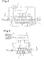
- FIG. 2 shows a schematic drawing of a leveling machine for leveling a metal strip.
- FIG. 3 shows a view similar to FIG. 2 , showing the most important controlled variables.
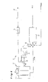
- FIG. 4 shows part of the closed-loop control system for carrying out the leveling process.
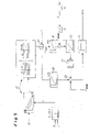
- FIG. 5 shows a more detailed representation of the closed-loop control system for carrying out the leveling process.
- FIGS. 1 a and 1 b show side views of a metal strip 1 that is to be subjected to a leveling process.
- the drawings show the leading end region of a strip that has not been rolled out.
- the thickness d of the metal strip 1 is not constant over the longitudinal axis of the strip, which corresponds to the strip transport direction R.
- FIG. 1 a shows the case of wedge-shaped thickness variation of the metal strip 1
- FIG. 1 b shows the case of stepped thickness variation of the strip 1 .
- a device 6 for measuring the thickness d of the metal strip in the form of a suitable sensor which in itself is already well known is installed upstream of the entry 7 of the leveling machine 2 with respect to the direction of transport R.
- the distance—measured in the transport direction R—between the sensor 6 and the middle of the leveling rolls 3 is denoted b.
- the sensor 6 measures the thickness d of the metal strip 1 and relays the measured value to an automatic control unit 9 .
- the adjustment a of the upper leveling rolls 3 relative to the lower leveling rolls 3 by the adjusting element 8 is carried out as a function of the measured thickness d.
- the delay time can be easily determined from the distance b and the conveyance speed v.
- a suitable algorithm is stored in the automatic control unit 9 , or the correct and suitable value of the yield point and thus of the adjustment a is determined on the basis of stored curves, and this adjustment value a is then set by the adjusting element 8 .
- FIG. 3 shows the general control concept for the automatically controlled adjustment a of the leveling rolls 3 .
- the automatic control unit 9 receives the measured thickness d of the metal strip 1 from the sensor 6 as an input parameter. In addition, it is supplied with the leveling force F, which is determined by a load cell or pressure transducer 10 .
- the deviation x of the metal strip 1 from the ideal line in the direction N normal to the surface of the metal strip 1 , which is measured at the exit 4 of the leveling machine 2 is supplied as an additional input variable to the automatic control unit 9 .
- strip data D which is stored in a database 17 , is available to the automatic control unit 9 .
- FIG. 4 shows some of the details of the automatic control engineering:
- the load cell or pressure transducer 10 detects the pressure p acting in the hydraulic adjusting elements 8 .
- the pressure p can be converted to the leveling force F by a converter 14 .
- the database 17 contains stored strip data D, i.e., for example, information on optimum deformation values for well-defined materials of which the strip 1 is composed.
- An optimum leveling force set point from the database 17 can be compared with the measured value in the subtract or 18 .
- the differential signal is processed in a slow, e.g., superposed, force controller 11 and then supplied to another subtractor 19 via a limiter 12 .
- the force controller 11 can also be designed to be switched off to realize different operating states, e.g., by means of a switch assigned to the force controller 11 .
- An optimum value for the set adjustment a from the database 17 and the measured value for the adjustment a are also supplied there.
- the differential signal is supplied to the controller 13 , which outputs a correcting value for the adjustment a to the adjusting elements 8 .
- the database 17 contains stored families of curves and tables, which, among other things, specify the yield point St of the material of the metal strip 1 to be processed, which is the optimum yield point for the leveling process.
- the left region of the database 17 contains families of curves, which define the present yield point St for predetermined strip thicknesses d.
- the hot-strip yield point from starting material for the cold rolling operation and the cold-strip yield point can be taken into consideration (possible initial points and end points of the families of curves).
- the sensor 6 supplies the actual value of the thickness d of the metal strip 1 .
- the conveyance speed v and the distance b see FIG. 2
- the optimum yield point St is determined from the actual thickness value and then transmitted to the region of the database 17 shown on the right.
- Stored data or stored algorithms are used to determine the required adjustment a and leveling force F with respect to the width B of the metal strip 1 (transverse to the transport direction R) as a function of the thickness d.
- Multiplication of this value by the actual width B in the multiplier 20 yields the set leveling force F soll .
- This value is supplied to a controller 21 , and the actual leveling force F Ist is subtracted in a subtractor located at the output end of the controller 21 .
- the actual leveling force F Ist is determined by the load cell or pressure transducer 10 and the converter 14 .
- the differential value is supplied to the controller 22 , whose signal is transmitted to a subtractor 23 via the limiter 12 .
- the target value for the adjustment a comes from the database 17 and likewise arrives at the subtractor 23 via a controller 24 .
- the measured value for the actual adjustment a is also received there as an input.
- the difference of the signal is sent to the (main) controller 13 , which outputs the correcting value for the adjustment a and supplies it to the adjusting elements 8 .
- the strip thickness is thus measured continuously, and the result is supplied to position-controlled hydraulic cylinders via the automatic control system explained above.
- the actual strip thicknesses are detected by the thickness measurement sensor 6 , and the adjustment values necessary for these thicknesses are made available by the position-controlled hydraulic cylinders.
- the closed-loop control system ensures continuous adjustment of the leveling rolls, which eliminates the strip thickness influence.
- a result-oriented automatic control process is used in that the deviation from the ideal position is also detected on the exit side.
- the measurement of the deviation or of the compressive loading of the load cell or pressure transducer 10 makes it possible to draw a conclusion about how the readjustment must be made in order to adjust to an optimum leveling result again.
- a largely bow-free exit of the metal strip 1 from the leveling machine 2 is thus achieved.
- the contact pressure in the hydraulic cylinders is detected. This pressure makes it possible to draw conclusions about the properties of the material, especially when the strip thickness is known. This data can also be evaluated for automatic position control and integrated in the closed-loop control system.
- the adjustment values and their variations are stored in the database 17 and can thus be used as starting values for presetting the leveling machine 2 when a different metal strip 1 is to be leveled or when a new installation is to be put into operation.
- any other desired types of sensors can be used, e.g., optical sensors.
Landscapes
- Engineering & Computer Science (AREA)
- Mechanical Engineering (AREA)
- Straightening Metal Sheet-Like Bodies (AREA)
- Attitude Control For Articles On Conveyors (AREA)
- Coating With Molten Metal (AREA)
- Control Of Metal Rolling (AREA)
- Wire Processing (AREA)
- Heat Treatment Of Strip Materials And Filament Materials (AREA)
Abstract
Description
- The invention concerns a method for leveling a metal strip, which is conveyed through a leveling machine in a direction of transport and leveled in the process, wherein the metal strip is acted upon in the leveling machine by a leveling force applied by a number of leveling rolls in the direction normal to the surface of the metal strip, wherein before the metal strip enters the leveling machine, its thickness is determined, and the leveling rolls are adjusted in the direction normal to the surface of the metal strip as a function of the determined thickness, wherein at the exit end of the leveling machine, a measurement is made to determine the bowing tendency and a deviation of the leveled metal strip from the ideal line in the direction normal to the surface of the metal strip, and wherein the adjustment of the leveling rolls in the direction normal to the surface of the metal strip is carried out as a function of the bowing tendency and of the deviation in such a way that the metal strip is as flat as possible after the leveling operation.
- In installations for the production and treatment of steel strip, the strip is usually delivered to the installation in coils for further processing or treatment. It is then received in an entry section and unwound, and in this way is threaded into the installation for treatment. The metal strip is conveyed into the installation by the unwinding reels. To do this, the bent leading end of the strip must be leveled to allow the strip to be threaded into the entry section of the installation and, if necessary, to allow trouble-free removal of the pieces of scrap at the leading end of the strip.
- The quality of the strip treatment and the quality of the strip as such depend on how successful the method is at bringing the initially coiled strip into a flat state. Leveling machines for accomplishing this are known which bring the initially uneven strip into a flat state by applying force to the strip with a number of leveling rolls.
- It is necessary, therefore, to use a suitable leveling procedure to ensure that the greatest possible degree of flatness exists after the leveling process. In a leveling machine designed as a roller leveling machine, usually three to seven rollers or rolls are used. To adjust to the strip thickness, the upper leveling rolls can be adjusted or set in the direction normal to the surface of the metal strip. Electric actuators or mechanical spindle-type lifting systems or sometimes exzenters are used for this purpose.
- A method of the aforementioned type is described in
DE 21 17 489 A1, in which a metal strip is fed to a leveling machine, where it is leveled in such a way that it leaves the machine as flat as possible. The thickness of the strip is measured upstream of the machine with respect to the direction of strip conveyance. Downstream of the machine, a displacement measuring device is provided, with which the deviation of the metal strip in the direction normal to the strip surface can be measured. This provides a measure of the flatness of the strip. - JP 62-214825 A describes a similar solution.
- EP 1 275 446 A2 discloses a method for eliminating cross-bow in metal strip in a strip processing line with a strip treatment device through which the metal strip passes. The cross-bow is detected in a section of the strip processing line and eliminated by means of a correcting roller with an adjustable depth of penetration. The cross-bow is eliminated in a section of the strip processing line immediately upstream of the strip treatment device.
- DE 102 30 449 A1 discloses a method for determining a position control quantity of a leveling roll for the correction of flatness deviations of a metal strip in a leveling machine. The disclosed method provides that actual coefficients of a shape function suitable for describing the shape of the strip are determined from detected values of the flatness deviations of the strip. Target coefficients are then determined from the actual coefficients. Finally, the target coefficients are converted to position control quantities for the leveling roll.
- DE 38 40 016 A1 discloses a method for leveling metal strip, wherein the leveling forces are measured on at least one of the leveling rolls of a roller leveling machine, and the leveling roll positions are adjusted as a function of the measured values. This method provides that each leveling force acting perpendicularly to the axes of rotation of the leveling rolls or of the roller bearings or to the frame of the leveling machine is separately measured and that, as a function of these measured values, the leveling rolls are automatically readjusted in the range of the varying compressive forces that arise.
- DE 33 08 616 C2 relates to a method for leveling metal strip, in which the metal strip is conveyed between staggered upper and lower leveling rolls and in the process is repeatedly bent in alternating directions with a decreasing degree of deformation, wherein the leveling rolls can be adjusted relative to one another to obtain a predetermined gradual reduction of the degree of deformation according to the cross section of the metal sheet and its nominal strength. In particular, the method provides that the leveling force on the leveling rolls is measured during the leveling process, the respective sheet strength is determined from the leveling force and the sheet cross section, and the adjustment of the leveling rolls is continuously corrected according to the given sheet strength.
- Other specific design solutions of leveling machines for metal strip or methods for their operation are disclosed in EP 0 765 196 B1, EP 0 182 062 B1, WO 02/076649 A1, DE 34 14 486 C2, DE 42 16 686 A1, EP 0 035 009 B1, and JP 11-192510.
- A problem that has not previously been considered is that, although the material properties of the metal strip to be leveled are taken into account, the leveling results are occasionally unsatisfactory due to variations in the thickness of the strip. Especially in the case of the strip ends, which are not rolled out, leveling is problematic, because the leading end of the strip and the trailing end of the strip show strong variation of the thickness of the strip. In some cases there are wedge-shaped or even stepped thickness variations over the longitudinal axis of the metal strip, so that a reproducible leveling process can be realized only with great difficulty.
- Therefore, the objective of the invention is to create a method of the type specified at the beginning, which makes it possible by simple means to overcome the aforementioned disadvantage, i.e., to ensure excellent leveling results even when the thickness of the metal strip varies greatly along its longitudinal axis.
- In accordance with the invention, the solution to this problem is characterized by the fact that a load measurement is used to determine the bowing tendency and the deviation.
- So that the thickness measurement can be made in a simple way, it is advantageous that it be made a sufficient distance upstream of the leveling rolls. Therefore, in accordance with a refinement of the invention, the leveling rolls are adjusted in a timed way that takes into account the distance of the thickness measurement upstream of the leveling rolls and the conveyance speed of the metal strip in the direction of transport. In other words, the distance of the measurement upstream of the rolls and the conveyance speed are used to determine a delay time, which is taken into consideration in the automatic control of the adjustment of the rolls.
- To ensure very high final quality of the strip with respect to its degree of flatness, it is provided that at the exit end of the leveling machine, a measurement is made to determine the bowing tendency and the deviation of the leveled metal strip from the ideal line, i.e., the ideal center plane, in the direction normal to the surface of the metal strip, and that the adjustment of the leveling rolls in the direction normal to the surface of the metal strip is carried out as a function of the bowing tendency and of the deviation in such a way that the metal strip is as flat as possible after the leveling operation.
- If the bowing tendency is determined by a load measurement, it is advantageous for the load measurement to be made by a leveling roll situated at the exit end. As an alternative to this, the load measurement can be made by one or more dancer rolls that are separate from the leveling rolls.
- A further improvement of the method of the invention can be realized by measuring the magnitude of the leveling force applied by the leveling rolls during the leveling process in the leveling machine and adjusting the leveling rolls in the direction normal to the surface of the metal strip additionally as a function of the measured leveling force. This makes it possible to compare the material-dependent set force/actual force.
- The direction of transport can be reversed if necessary. This can be useful if the leveled strip downstream of the leveling machine does not meet the desired flatness requirements. In this case, the adjustment values between the entry end of the leveling machine and the exit end of the leveling machine are mirrored in such a way that the adjustment values in the reverse transport direction correspond to the adjustment values in the transport direction. In this way, the leading end of the strip can be leveled a second time in the reverse transport direction in such a way that it comes to rest at the entry side of the leveling machine with an optimum leveling result. Optionally, the strip can be leveled a third time in the forward transport direction, or the leading end of the strip can be further conveyed through the opened machine.
- It is preferred that position-controlled adjusting elements be used, which are suitable for adjusting the leveling rolls in the direction normal to the surface of the metal strip. In this connection, it is especially advantageous for the position-controlled adjusting elements to be designed as hydraulic piston-cylinder systems.
- Finally, means can be provided for measuring the bowing tendency and the deviation of the leveled metal strip from the ideal line in the direction normal to the surface of the metal strip, which means are situated at the exit of the metal strip from the leveling machine or downstream of the exit from the leveling machine with respect to the direction of transport. These means can consist of one or two (upper, lower) dancer rolls that are separate from the leveling rolls.
- The invention makes it possible to achieve very good leveling results even with strongly varying thickness of the metal strip to be leveled. This has the overall result of improving the quality of the metal strip produced and of making the process of producing the strip simpler and more reliable.
- The drawings illustrate a specific embodiment of the invention.
-
FIGS. 1 a and 1 b show schematic side views of an end section of a metal strip. -
FIG. 2 shows a schematic drawing of a leveling machine for leveling a metal strip. -
FIG. 3 shows a view similar toFIG. 2 , showing the most important controlled variables. -
FIG. 4 shows part of the closed-loop control system for carrying out the leveling process. -
FIG. 5 shows a more detailed representation of the closed-loop control system for carrying out the leveling process. -
FIGS. 1 a and 1 b show side views of a metal strip 1 that is to be subjected to a leveling process. The drawings show the leading end region of a strip that has not been rolled out. Typically, the thickness d of the metal strip 1 is not constant over the longitudinal axis of the strip, which corresponds to the strip transport direction R.FIG. 1 a shows the case of wedge-shaped thickness variation of the metal strip 1, whileFIG. 1 b shows the case of stepped thickness variation of the strip 1. - Leveling a metal strip of this type is extremely difficult and can be efficiently accomplished only with the
leveling machine 2 of the type shown inFIG. 2 . - The metal strip 1 is conveyed into the
leveling machine 2 in transport direction R at a constant speed v. Theleveling machine 2 is designed as a roller leveling machine and has a number ofleveling rolls 3. The three upper and fourlower leveling rolls 3 are installed onsupports lower support 16 is mounted in a stationary way, while theupper support 15 can be moved in direction N by means of a position-controlledadjusting element 8 in the form of a hydraulic piston-cylinder system. The adjusting motion of the leveling rolls 3 is designated a. When the leveling rolls 3 are adjusted, the force designated F acts between the rolls and produces deformation of the metal strip 1, so that the metal strip 1 has a high degree of flatness after it exits the levelingmachine 2. - In this connection, the goal is for the metal strip 1 to assume the shape represented by the solid lines downstream of the
exit 4 of the leveling machine 2 (ideal line). However, in general, without extensive measures, it is to be expected that the metal strip 1 will have a bowing tendency, which manifests itself in either an upward or downward deviation x from the ideal line, as indicated by the broken lines. - To prevent this, the following procedure is followed: A
device 6 for measuring the thickness d of the metal strip in the form of a suitable sensor which in itself is already well known is installed upstream of the entry 7 of the levelingmachine 2 with respect to the direction of transport R. The distance—measured in the transport direction R—between thesensor 6 and the middle of the leveling rolls 3 is denoted b. - The
sensor 6 measures the thickness d of the metal strip 1 and relays the measured value to anautomatic control unit 9. The adjustment a of the upper leveling rolls 3 relative to the lower leveling rolls 3 by the adjustingelement 8 is carried out as a function of the measured thickness d. In this connection, it is also necessary to take into account the delay time that elapses until the metal strip 1 has moved from the location of the measurement to the location of the leveling rolls 3. The delay time can be easily determined from the distance b and the conveyance speed v. - To find the correct amount for the adjustment a, a suitable algorithm is stored in the
automatic control unit 9, or the correct and suitable value of the yield point and thus of the adjustment a is determined on the basis of stored curves, and this adjustment value a is then set by the adjustingelement 8. - A dancer roll 5, which detects the deviation x of the metal strip 1 from the ideal position, is mounted at the
exit 4 of the leveling machine. The measured deviation value is likewise relayed to theautomatic control unit 9, which corrects the adjustment a on the basis of its internally stored algorithms or curves. Instead of a separate dancer roll 5, this measurement can also be carried out with thelast leveling roll 3′ in the transport direction R. -
FIG. 3 shows the general control concept for the automatically controlled adjustment a of the leveling rolls 3. Theautomatic control unit 9 receives the measured thickness d of the metal strip 1 from thesensor 6 as an input parameter. In addition, it is supplied with the leveling force F, which is determined by a load cell orpressure transducer 10. The deviation x of the metal strip 1 from the ideal line in the direction N normal to the surface of the metal strip 1, which is measured at theexit 4 of the levelingmachine 2, is supplied as an additional input variable to theautomatic control unit 9. This figure also shows that strip data D, which is stored in adatabase 17, is available to theautomatic control unit 9. - The
automatic control unit 9 contains a stored algorithm or a table, which uses the thickness d, the deviation x, the leveling force F, and the strip data D to determine the adjustment a necessary to achieve optimum work results. This is represented inFIG. 3 as the functional relationship a=f(d, x, F, D). -
FIG. 4 shows some of the details of the automatic control engineering: The load cell orpressure transducer 10 detects the pressure p acting in thehydraulic adjusting elements 8. The pressure p can be converted to the leveling force F by aconverter 14. Thedatabase 17 contains stored strip data D, i.e., for example, information on optimum deformation values for well-defined materials of which the strip 1 is composed. An optimum leveling force set point from thedatabase 17 can be compared with the measured value in the subtract or 18. The differential signal is processed in a slow, e.g., superposed,force controller 11 and then supplied to anothersubtractor 19 via alimiter 12. Theforce controller 11 can also be designed to be switched off to realize different operating states, e.g., by means of a switch assigned to theforce controller 11. An optimum value for the set adjustment a from thedatabase 17 and the measured value for the adjustment a are also supplied there. The differential signal is supplied to thecontroller 13, which outputs a correcting value for the adjustment a to the adjustingelements 8. - Further details on the automatic control setup are shown in
FIG. 5 . Thedatabase 17 contains stored families of curves and tables, which, among other things, specify the yield point St of the material of the metal strip 1 to be processed, which is the optimum yield point for the leveling process. The left region of thedatabase 17 contains families of curves, which define the present yield point St for predetermined strip thicknesses d. In this regard, the hot-strip yield point from starting material for the cold rolling operation and the cold-strip yield point can be taken into consideration (possible initial points and end points of the families of curves). Thesensor 6 supplies the actual value of the thickness d of the metal strip 1. When the conveyance speed v and the distance b (seeFIG. 2 ) are known, it is possible to determine the time required for the metal strip 1 to reach the location of the leveling rolls 3 from the location of the thickness measurement. This is indicated inFIG. 5 by the delay time element TT as a function of the speed v. - In the region of the
database 17 shown on the left inFIG. 5 , the optimum yield point St is determined from the actual thickness value and then transmitted to the region of thedatabase 17 shown on the right. Stored data or stored algorithms are used to determine the required adjustment a and leveling force F with respect to the width B of the metal strip 1 (transverse to the transport direction R) as a function of the thickness d. - Multiplication of this value by the actual width B in the
multiplier 20 yields the set leveling force Fsoll. This value is supplied to acontroller 21, and the actual leveling force FIst is subtracted in a subtractor located at the output end of thecontroller 21. The actual leveling force FIst is determined by the load cell orpressure transducer 10 and theconverter 14. The differential value is supplied to thecontroller 22, whose signal is transmitted to asubtractor 23 via thelimiter 12. - The target value for the adjustment a comes from the
database 17 and likewise arrives at thesubtractor 23 via acontroller 24. The measured value for the actual adjustment a is also received there as an input. The difference of the signal is sent to the (main)controller 13, which outputs the correcting value for the adjustment a and supplies it to the adjustingelements 8. - The case in which there is only one adjusting
element 8 is illustrated, although preferably one adjustingelement 8 is installed at each end of thesupports - In the present embodiment, the strip thickness is thus measured continuously, and the result is supplied to position-controlled hydraulic cylinders via the automatic control system explained above. The actual strip thicknesses are detected by the
thickness measurement sensor 6, and the adjustment values necessary for these thicknesses are made available by the position-controlled hydraulic cylinders. The closed-loop control system ensures continuous adjustment of the leveling rolls, which eliminates the strip thickness influence. - To eliminate the effects of the strength of the metal strip 1, a result-oriented automatic control process is used in that the deviation from the ideal position is also detected on the exit side. The measurement of the deviation or of the compressive loading of the load cell or
pressure transducer 10 makes it possible to draw a conclusion about how the readjustment must be made in order to adjust to an optimum leveling result again. A largely bow-free exit of the metal strip 1 from the levelingmachine 2 is thus achieved. In addition, the contact pressure in the hydraulic cylinders is detected. This pressure makes it possible to draw conclusions about the properties of the material, especially when the strip thickness is known. This data can also be evaluated for automatic position control and integrated in the closed-loop control system. - The adjustment values and their variations are stored in the
database 17 and can thus be used as starting values for presetting the levelingmachine 2 when a different metal strip 1 is to be leveled or when a new installation is to be put into operation. - Instead of the specified sensors (for the thickness d, the deviation x and the leveling force F), any other desired types of sensors can be used, e.g., optical sensors.
-
- 1 metal strip
- 2 leveling machine
- 3 leveling roll
- 3′ leveling roll
- 4 exit end
- 5 dancer roll
- 6 means for measuring the thickness
- 7 entry end
- 8 position-controlled adjusting element
- 9 automatic control unit
- 10 load cell/pressure transducer
- 11 slow force controller
- 12 limiter
- 13 controller (P controller)
- 14 converter
- 15 support
- 16 support
- 17 database
- 18 subtractor
- 19 subtractor
- 20 multiplier
- 21 controller
- 22 controller
- 23 subtractor
- 24 controller
- R transport direction
- N direction normal to the surface of the metal strip
- F leveling force
- d thickness of the metal strip
- a adjustment of the leveling rolls
- b upstream distance of the thickness measurement from the leveling rolls
- v conveyance speed
- x deviation of the leveled metal strip
- D strip data (database)
- p pressure
- St yield point
- B width of the metal strip
Claims (14)
Applications Claiming Priority (3)
| Application Number | Priority Date | Filing Date | Title |
|---|---|---|---|
| DE102004041732A DE102004041732A1 (en) | 2004-08-28 | 2004-08-28 | Method of straightening a metal strip and straightening machine |
| DE102004041732.6 | 2004-08-28 | ||
| PCT/EP2005/008899 WO2006024393A1 (en) | 2004-08-28 | 2005-08-16 | Method for straightening a metal strip and straightening machine |
Publications (2)
| Publication Number | Publication Date |
|---|---|
| US20080098784A1 true US20080098784A1 (en) | 2008-05-01 |
| US7530250B2 US7530250B2 (en) | 2009-05-12 |
Family
ID=35058992
Family Applications (1)
| Application Number | Title | Priority Date | Filing Date |
|---|---|---|---|
| US11/661,648 Expired - Fee Related US7530250B2 (en) | 2004-08-28 | 2005-08-16 | Method for straightening a metal strip and straightening machine |
Country Status (17)
| Country | Link |
|---|---|
| US (1) | US7530250B2 (en) |
| EP (1) | EP1781429B1 (en) |
| JP (1) | JP4781361B2 (en) |
| KR (1) | KR101141949B1 (en) |
| CN (1) | CN100418656C (en) |
| AT (1) | ATE401144T1 (en) |
| AU (1) | AU2005279410B2 (en) |
| BR (1) | BRPI0514803A (en) |
| CA (1) | CA2578152C (en) |
| DE (2) | DE102004041732A1 (en) |
| ES (1) | ES2307203T3 (en) |
| MX (1) | MX2007002365A (en) |
| MY (1) | MY139599A (en) |
| PL (1) | PL1781429T3 (en) |
| RU (1) | RU2346773C2 (en) |
| TW (1) | TWI332866B (en) |
| WO (1) | WO2006024393A1 (en) |
Cited By (7)
| Publication number | Priority date | Publication date | Assignee | Title |
|---|---|---|---|---|
| US20090307889A1 (en) * | 2006-06-19 | 2009-12-17 | Bertram Schulze | Uncoiling Device |
| US20100154499A1 (en) * | 2007-05-30 | 2010-06-24 | Peter Hug | Method and device for adjusting a flexer station during the rounding of metal sheets |
| US20110138868A1 (en) * | 2008-07-10 | 2011-06-16 | Arku Maschinenbau Gmbh | Method for Leveling Parts in a Roller Leveling Machine |
| KR101537419B1 (en) * | 2008-05-16 | 2015-07-16 | 베베게베르그베르크-운트발 쯔베르크-마쉬넨바우게엠베하 | METHOD AND APPARATUS FOR LEVELING METAL STRIP |
| CN105598213A (en) * | 2016-01-25 | 2016-05-25 | 江西瑞林装备有限公司 | System and method for controlling rolling reduction of metal plate straightening machine |
| US11389848B2 (en) * | 2018-06-12 | 2022-07-19 | Dalian Field Heavy-Machinery Manufacturing Co., Ltd | Flattening device, conveying apparatus and processing system |
| CN117206363A (en) * | 2023-08-31 | 2023-12-12 | 宝武集团鄂城钢铁有限公司 | A method for straightening the unevenness of ultra-thick steel plates with a thickness of 180 to 280 mm |
Families Citing this family (32)
| Publication number | Priority date | Publication date | Assignee | Title |
|---|---|---|---|---|
| KR100869512B1 (en) * | 2007-07-24 | 2008-11-19 | 신스틸 주식회사 | Leveler and its control method |
| JP5380879B2 (en) * | 2008-03-31 | 2014-01-08 | Jfeスチール株式会社 | Automatic correction control method for differential thickness steel sheet and manufacturing method for differential thickness steel sheet |
| FR2937267B1 (en) * | 2008-10-17 | 2010-11-12 | Dimeco Alipresse | DEVICE FOR RECOVERING AND MAINTAINING A BAND OF SEMI-RIGID MATERIAL IN A MACHINE |
| CN101733308B (en) * | 2008-11-17 | 2012-02-01 | 鞍钢股份有限公司 | Method for protecting straightening force of inlet and outlet of hot straightening machine |
| CN102137943B (en) * | 2009-04-22 | 2013-01-09 | 新日铁工程技术株式会社 | Cold-rolled steel sheet production method and production facility |
| DE102009041852A1 (en) * | 2009-09-18 | 2011-04-07 | Bwg Bergwerk- Und Walzwerk-Maschinenbau Gmbh | Method and apparatus for continuous stretch bending of metal strips |
| CN102096393B (en) * | 2009-12-14 | 2012-10-10 | 宝山钢铁股份有限公司 | Method for dynamically limiting amplitude during non-automatic control of straightening machine and system thereof |
| DE102010024714C5 (en) * | 2010-06-23 | 2018-10-18 | Bwg Bergwerk- Und Walzwerk-Maschinenbau Gmbh | Method for stretch bending of metal strips and stretch bending plant |
| DE102010049648A1 (en) * | 2010-10-28 | 2012-05-03 | Maschinenfabrik - Fr. W. Schnutz Gmbh & Co. Kg | Method and device for planing perforated sheets |
| DE102010061841A1 (en) | 2010-11-24 | 2012-05-24 | Sms Siemag Ag | Method for directing metal strip of commission, involves determining and weighing initialization immersion depth for next straightening process according to deviation of strip-shape measuring data and initialization immersion depth |
| JP2012171005A (en) * | 2011-02-24 | 2012-09-10 | Jp Steel Plantech Co | Roller leveler and straightening method of metal plate |
| US20120227452A1 (en) * | 2011-03-07 | 2012-09-13 | Toyota Motor Engineering & Manufacturing North America, Inc. | Method and system for controlling the quality of a stamped part |
| WO2013035449A1 (en) * | 2011-09-07 | 2013-03-14 | スチールプランテック株式会社 | Roller leveler and metal plate leveling method using same |
| DE102012204074A1 (en) | 2012-03-15 | 2013-09-19 | Sms Siemag Ag | Device for straightening metal strip |
| JP6133696B2 (en) * | 2013-06-12 | 2017-05-24 | オリイメック株式会社 | Leveler feeder |
| CN103272855B (en) * | 2013-06-13 | 2015-11-18 | 北京首钢自动化信息技术有限公司 | A kind of method improving inlet of rolling mill thickness and precision in preset model calculates |
| JP5598583B2 (en) * | 2013-07-30 | 2014-10-01 | Jfeスチール株式会社 | Automatic straightening control device for differential steel plate |
| DE102015102271C9 (en) * | 2014-02-26 | 2023-05-25 | Arku Maschinenbau Gmbh | Method and device for straightening metal parts with pinch point reduction |
| DE102014205900A1 (en) * | 2014-03-28 | 2015-10-01 | Sms Group Gmbh | Method for adjusting a straightening roller of a leveling machine |
| CN105483343B (en) * | 2014-09-17 | 2017-06-23 | 宝山钢铁股份有限公司 | Medium and Heavy Plate Rolling Production linear velocity control method for improving steel plate flatness |
| CN104384244B (en) * | 2014-09-30 | 2017-05-24 | 巢湖广丰金属制品有限公司 | Fine shaping equipment applied to strip steel |
| US10010918B2 (en) * | 2016-10-05 | 2018-07-03 | Allor Manufacturing Inc. | Device and method for leveling a metal plate |
| TWI647021B (en) * | 2017-02-08 | 2019-01-11 | 國立清華大學 | Intelligent coil leveling validating system and validating method thereof |
| CN108273871B (en) * | 2018-04-09 | 2020-06-02 | 包头钢铁(集团)有限责任公司 | Method for straightening middle-low grade non-oriented silicon steel by straight-end machine |
| CN108326078A (en) * | 2018-04-09 | 2018-07-27 | 包头钢铁(集团)有限责任公司 | The method that coil opener aligns mild steel |
| CN108526248A (en) * | 2018-04-09 | 2018-09-14 | 包头钢铁(集团)有限责任公司 | The method that coil opener aligns medium carbon steel |
| CN108435830A (en) * | 2018-04-09 | 2018-08-24 | 包头钢铁(集团)有限责任公司 | The method that coil opener aligns IF steel |
| CN108655208B (en) * | 2018-05-29 | 2019-11-19 | 攀钢集团攀枝花钢钒有限公司 | Method for measuring and controlling straightening state of straightening machine and system for measuring and controlling straightening state of straightening machine |
| AT522234B1 (en) * | 2019-02-28 | 2022-05-15 | Evg Entwicklungs U Verwertungs Ges M B H | Method and device for straightening wire or strip material |
| CN112318450B (en) * | 2020-10-20 | 2025-06-13 | 北京京诚之星科技开发有限公司 | An efficient roll changing system for wide and thick plate straightening machine |
| DE102021203357A1 (en) * | 2021-04-01 | 2022-10-06 | Sms Group Gmbh | Method and control device for operating a strip treatment plant for processing a strip, in particular a metal strip or rolled stock |
| DE102022122115A1 (en) | 2022-09-01 | 2024-03-07 | Biegeform Solutions GmbH | straightener |
Citations (8)
| Publication number | Priority date | Publication date | Assignee | Title |
|---|---|---|---|---|
| US3587263A (en) * | 1968-12-10 | 1971-06-28 | Westinghouse Electric Corp | Method and apparatus for steering strip material through rolling mills |
| US5535610A (en) * | 1993-07-13 | 1996-07-16 | Bwg Bergwerk-Und Walzwerk-Maschinenbau Gmbh | Method and apparatus for eliminating crossbow in metal strip |
| US5666836A (en) * | 1994-02-01 | 1997-09-16 | Clecim | Process and installation for planishing a thin metal strip |
| US5687595A (en) * | 1995-06-03 | 1997-11-18 | Bwg Bergwerk- Und Walzwerk-Maschinenbau Gmbh | Method of and apparatus for correcting curvature of rolled metal strip |
| US6357273B1 (en) * | 1999-10-21 | 2002-03-19 | Bwg Bergwerk- Und Walzwerk- Maschinenbau Gmbh | Method of reducing waste in the rolling of strip segments interconnected by weld seams |
| US6857301B1 (en) * | 2002-10-16 | 2005-02-22 | Machine Concepts, Inc. | Displacement-type shape sensor for multi-roll leveler |
| US7185519B2 (en) * | 2003-09-15 | 2007-03-06 | The Bradbury Company, Inc. | Methods and apparatus for monitoring and conditioning strip material |
| US7383711B2 (en) * | 2005-06-10 | 2008-06-10 | Blue Ip, Inc. | CNC leveler |
Family Cites Families (17)
| Publication number | Priority date | Publication date | Assignee | Title |
|---|---|---|---|---|
| DE2117489A1 (en) * | 1970-04-10 | 1971-10-28 | Hugh Smith (Glasgow) Ltd., Glasgow; Jeffrey, David Cockburn, Beardsen, Dunbaiton; (Großbritannien) | Control unit for sheet leveler |
| AT365485B (en) | 1980-02-21 | 1982-01-25 | Voest Alpine Ag | DEVICE FOR SUPPORTING A WORK ROLL OF A BENDING OR LEVELING MACHINE |
| DE3308616C2 (en) | 1983-03-11 | 1993-11-25 | Schloemann Siemag Ag | Method and machine for straightening sheet metal |
| DE3414486C2 (en) | 1984-04-17 | 1994-06-01 | Manfred Wanzke | Straightening machine for sheet metal strip |
| DE3437777A1 (en) | 1984-10-16 | 1986-04-24 | Fr. W. Schnutz GmbH & Co, 5900 Siegen | SUPPORT ROLLER ADJUSTMENT FOR LEVELING MACHINES |
| SU1295198A1 (en) * | 1985-03-05 | 1987-03-07 | Производственное объединение "Уралмаш" | Method for checking curvature of rolled products |
| JPS62214825A (en) * | 1986-03-17 | 1987-09-21 | Mitsubishi Heavy Ind Ltd | Roller leveler |
| JPS62215825A (en) * | 1986-03-18 | 1987-09-22 | Toyoda Mach Works Ltd | Measuring apparatus |
| DE3840016A1 (en) | 1988-11-26 | 1990-05-31 | Schloemann Siemag Ag | METHOD FOR LEVELING SHEETS, STRIPS, TABLES, PROFILES, CARRIERS ETC. |
| DE4216686A1 (en) | 1992-05-21 | 1993-11-25 | Schloemann Siemag Ag | Process and straightening machine for straightening sheets and strips |
| FR2732912A1 (en) | 1995-04-14 | 1996-10-18 | Clecim Sa | Nested roller planer |
| RU2062152C1 (en) * | 1994-07-20 | 1996-06-20 | Акционерное общество "Магнитогорский металлургический комбинат" | Strip metal straightening method |
| CN2309192Y (en) * | 1997-09-12 | 1999-03-03 | 中国第二重型机械集团公司 | Hot plate-straightening machine |
| JPH11192510A (en) | 1998-01-07 | 1999-07-21 | Nippon Steel Corp | Roller leveler roll position control method |
| DE10113664A1 (en) | 2001-03-21 | 2002-09-26 | Sms Demag Ag | Straightening machine for straightening especially the beginning and end of rolled metal strips or sheets comprises offset upper and lower driven straightening rollers |
| DE10124836C5 (en) | 2001-05-22 | 2007-07-19 | Bwg Bergwerk- Und Walzwerk-Maschinenbau Gmbh | Method for eliminating transverse curvatures in a metal strip |
| DE10230449A1 (en) | 2002-07-06 | 2004-01-15 | BFI VDEh-Institut für angewandte Forschung GmbH | Determining straightening roller position control parameter involves deriving shape function coefficients from flatness errors, deriving target coefficients, converting to position control parameters |
-
2004
- 2004-08-28 DE DE102004041732A patent/DE102004041732A1/en not_active Withdrawn
-
2005
- 2005-08-16 CA CA2578152A patent/CA2578152C/en not_active Expired - Fee Related
- 2005-08-16 ES ES05777248T patent/ES2307203T3/en not_active Expired - Lifetime
- 2005-08-16 KR KR1020067027563A patent/KR101141949B1/en not_active Expired - Fee Related
- 2005-08-16 RU RU2007102680/02A patent/RU2346773C2/en not_active IP Right Cessation
- 2005-08-16 BR BRPI0514803-0A patent/BRPI0514803A/en not_active IP Right Cessation
- 2005-08-16 EP EP05777248A patent/EP1781429B1/en not_active Revoked
- 2005-08-16 CN CNB2005800251719A patent/CN100418656C/en not_active Expired - Fee Related
- 2005-08-16 JP JP2007528691A patent/JP4781361B2/en not_active Expired - Fee Related
- 2005-08-16 AT AT05777248T patent/ATE401144T1/en active
- 2005-08-16 WO PCT/EP2005/008899 patent/WO2006024393A1/en not_active Ceased
- 2005-08-16 US US11/661,648 patent/US7530250B2/en not_active Expired - Fee Related
- 2005-08-16 AU AU2005279410A patent/AU2005279410B2/en not_active Ceased
- 2005-08-16 DE DE502005004745T patent/DE502005004745D1/en not_active Expired - Lifetime
- 2005-08-16 MX MX2007002365A patent/MX2007002365A/en active IP Right Grant
- 2005-08-16 PL PL05777248T patent/PL1781429T3/en unknown
- 2005-08-18 TW TW094128177A patent/TWI332866B/en not_active IP Right Cessation
- 2005-08-25 MY MYPI20053992A patent/MY139599A/en unknown
Patent Citations (8)
| Publication number | Priority date | Publication date | Assignee | Title |
|---|---|---|---|---|
| US3587263A (en) * | 1968-12-10 | 1971-06-28 | Westinghouse Electric Corp | Method and apparatus for steering strip material through rolling mills |
| US5535610A (en) * | 1993-07-13 | 1996-07-16 | Bwg Bergwerk-Und Walzwerk-Maschinenbau Gmbh | Method and apparatus for eliminating crossbow in metal strip |
| US5666836A (en) * | 1994-02-01 | 1997-09-16 | Clecim | Process and installation for planishing a thin metal strip |
| US5687595A (en) * | 1995-06-03 | 1997-11-18 | Bwg Bergwerk- Und Walzwerk-Maschinenbau Gmbh | Method of and apparatus for correcting curvature of rolled metal strip |
| US6357273B1 (en) * | 1999-10-21 | 2002-03-19 | Bwg Bergwerk- Und Walzwerk- Maschinenbau Gmbh | Method of reducing waste in the rolling of strip segments interconnected by weld seams |
| US6857301B1 (en) * | 2002-10-16 | 2005-02-22 | Machine Concepts, Inc. | Displacement-type shape sensor for multi-roll leveler |
| US7185519B2 (en) * | 2003-09-15 | 2007-03-06 | The Bradbury Company, Inc. | Methods and apparatus for monitoring and conditioning strip material |
| US7383711B2 (en) * | 2005-06-10 | 2008-06-10 | Blue Ip, Inc. | CNC leveler |
Cited By (10)
| Publication number | Priority date | Publication date | Assignee | Title |
|---|---|---|---|---|
| US20090307889A1 (en) * | 2006-06-19 | 2009-12-17 | Bertram Schulze | Uncoiling Device |
| US8136215B2 (en) * | 2006-06-19 | 2012-03-20 | Siemens Aktiengesellschaft | Uncoiling device |
| US20100154499A1 (en) * | 2007-05-30 | 2010-06-24 | Peter Hug | Method and device for adjusting a flexer station during the rounding of metal sheets |
| US8573013B2 (en) * | 2007-05-30 | 2013-11-05 | Soudronic Ag | Method and device for adjusting a flexer station during the rounding of metal sheets |
| KR101537419B1 (en) * | 2008-05-16 | 2015-07-16 | 베베게베르그베르크-운트발 쯔베르크-마쉬넨바우게엠베하 | METHOD AND APPARATUS FOR LEVELING METAL STRIP |
| US20110138868A1 (en) * | 2008-07-10 | 2011-06-16 | Arku Maschinenbau Gmbh | Method for Leveling Parts in a Roller Leveling Machine |
| US8789399B2 (en) * | 2008-07-10 | 2014-07-29 | Arku Maschinenbau Gmbh | Method for leveling parts in a roller leveling machine |
| CN105598213A (en) * | 2016-01-25 | 2016-05-25 | 江西瑞林装备有限公司 | System and method for controlling rolling reduction of metal plate straightening machine |
| US11389848B2 (en) * | 2018-06-12 | 2022-07-19 | Dalian Field Heavy-Machinery Manufacturing Co., Ltd | Flattening device, conveying apparatus and processing system |
| CN117206363A (en) * | 2023-08-31 | 2023-12-12 | 宝武集团鄂城钢铁有限公司 | A method for straightening the unevenness of ultra-thick steel plates with a thickness of 180 to 280 mm |
Also Published As
| Publication number | Publication date |
|---|---|
| CN100418656C (en) | 2008-09-17 |
| AU2005279410B2 (en) | 2010-04-15 |
| CA2578152C (en) | 2012-06-05 |
| TWI332866B (en) | 2010-11-11 |
| MX2007002365A (en) | 2007-05-11 |
| TW200609052A (en) | 2006-03-16 |
| RU2346773C2 (en) | 2009-02-20 |
| JP4781361B2 (en) | 2011-09-28 |
| WO2006024393A1 (en) | 2006-03-09 |
| EP1781429B1 (en) | 2008-07-16 |
| JP2008511445A (en) | 2008-04-17 |
| US7530250B2 (en) | 2009-05-12 |
| ATE401144T1 (en) | 2008-08-15 |
| KR101141949B1 (en) | 2012-05-07 |
| DE102004041732A1 (en) | 2006-03-02 |
| CA2578152A1 (en) | 2006-03-09 |
| DE502005004745D1 (en) | 2008-08-28 |
| ES2307203T3 (en) | 2008-11-16 |
| AU2005279410A1 (en) | 2006-03-09 |
| PL1781429T3 (en) | 2008-12-31 |
| CN101068631A (en) | 2007-11-07 |
| RU2007102680A (en) | 2008-07-27 |
| KR20070042932A (en) | 2007-04-24 |
| EP1781429A1 (en) | 2007-05-09 |
| MY139599A (en) | 2009-10-30 |
| BRPI0514803A (en) | 2008-06-24 |
Similar Documents
| Publication | Publication Date | Title |
|---|---|---|
| US7530250B2 (en) | Method for straightening a metal strip and straightening machine | |
| EP0294807B1 (en) | Rolling installation for and rolling method of continuous cast strip | |
| CN1283380C (en) | Cold rolling mill and method for cold roll forming metallic strip | |
| EP3655173B1 (en) | Systems and methods for controlling flatness of a metal substrate with low pressure rolling | |
| ZA200705219B (en) | Process and device for intentionally influencing the geometry of roughed-down strips in a roughing-down stand | |
| KR100241167B1 (en) | Hot-rolling method of steel piece joint during continuous hot-rolling | |
| JPS59197309A (en) | Strip producing method and apparatus equipped with high strip profile quality and strip flatness quality | |
| US12240023B2 (en) | Flatness-measuring device, hot-rolling mill and method for operating a flatness-measuring device | |
| US20120151980A1 (en) | Method for adjusting the rolls of a roll stand and roll stand | |
| US7854155B2 (en) | Method and rolling mill for improving the running-out of a rolled metal strip whose trailing end is moving at rolling speed | |
| US20020174699A1 (en) | Method of and apparatus for eliminating crossbow in metal strip | |
| JP2011088172A (en) | Device and method for controlling sheet thickness in cold rolling mill | |
| KR102314633B1 (en) | Cold rolled steel sheet rolling apparatus capable of shape control and control method therefor | |
| JP2002126811A (en) | Cold rolling equipment and cold rolling method | |
| TWI746756B (en) | Method and device for rolling metal strips | |
| JPS637362Y2 (en) | ||
| US5860311A (en) | Method to guide the strip between the stands in a rolling mill finishing train and relative device | |
| JP4055218B2 (en) | Stainless steel sheet manufacturing method | |
| JP7622236B2 (en) | Rolling that minimizes the decrease in bending force during entry | |
| JP4330132B2 (en) | Temper rolling method | |
| JPS62244506A (en) | Setting up method for edge drop control of sheet rolling | |
| KR20180129350A (en) | Cold rolling mill | |
| JP2006159220A (en) | Cold rolling equipment and cold tandem rolling method | |
| JPH0515911A (en) | Edge drop control method in cold rolling. | |
| JPH07112561B2 (en) | Temper rolling method of continuous annealing equipment |
Legal Events
| Date | Code | Title | Description |
|---|---|---|---|
| AS | Assignment |
Owner name: SMS DEMAG AG, GERMANY Free format text: ASSIGNMENT OF ASSIGNORS INTEREST;ASSIGNORS:HARTUNG, HANS-GEORG;GRAMER, ANDREAS;SOHL, RALF-HARTMUT;AND OTHERS;REEL/FRAME:019017/0057;SIGNING DATES FROM 20070119 TO 20070131 |
|
| FEPP | Fee payment procedure |
Free format text: PAYOR NUMBER ASSIGNED (ORIGINAL EVENT CODE: ASPN); ENTITY STATUS OF PATENT OWNER: LARGE ENTITY |
|
| AS | Assignment |
Owner name: SMS SIEMAG AKTIENGESELLSCHAFT, GERMANY Free format text: CHANGE OF NAME;ASSIGNOR:SMS DEMAG AG;REEL/FRAME:025192/0325 Effective date: 20090325 |
|
| REMI | Maintenance fee reminder mailed | ||
| LAPS | Lapse for failure to pay maintenance fees | ||
| STCH | Information on status: patent discontinuation |
Free format text: PATENT EXPIRED DUE TO NONPAYMENT OF MAINTENANCE FEES UNDER 37 CFR 1.362 |
|
| STCH | Information on status: patent discontinuation |
Free format text: PATENT EXPIRED DUE TO NONPAYMENT OF MAINTENANCE FEES UNDER 37 CFR 1.362 |
|
| FP | Lapsed due to failure to pay maintenance fee |
Effective date: 20130512 |