US20060150737A1 - Method for detecting structure-borne noise events in a roller bearing - Google Patents
Method for detecting structure-borne noise events in a roller bearing Download PDFInfo
- Publication number
- US20060150737A1 US20060150737A1 US10/543,844 US54384405A US2006150737A1 US 20060150737 A1 US20060150737 A1 US 20060150737A1 US 54384405 A US54384405 A US 54384405A US 2006150737 A1 US2006150737 A1 US 2006150737A1
- Authority
- US
- United States
- Prior art keywords
- variance
- value
- roller bearing
- equation
- signal
- Prior art date
- Legal status (The legal status is an assumption and is not a legal conclusion. Google has not performed a legal analysis and makes no representation as to the accuracy of the status listed.)
- Granted
Links
Images


Classifications
-
- G—PHYSICS
- G01—MEASURING; TESTING
- G01M—TESTING STATIC OR DYNAMIC BALANCE OF MACHINES OR STRUCTURES; TESTING OF STRUCTURES OR APPARATUS, NOT OTHERWISE PROVIDED FOR
- G01M13/00—Testing of machine parts
- G01M13/04—Bearings
- G01M13/045—Acoustic or vibration analysis
-
- F—MECHANICAL ENGINEERING; LIGHTING; HEATING; WEAPONS; BLASTING
- F16—ENGINEERING ELEMENTS AND UNITS; GENERAL MEASURES FOR PRODUCING AND MAINTAINING EFFECTIVE FUNCTIONING OF MACHINES OR INSTALLATIONS; THERMAL INSULATION IN GENERAL
- F16C—SHAFTS; FLEXIBLE SHAFTS; ELEMENTS OR CRANKSHAFT MECHANISMS; ROTARY BODIES OTHER THAN GEARING ELEMENTS; BEARINGS
- F16C19/00—Bearings with rolling contact, for exclusively rotary movement
- F16C19/52—Bearings with rolling contact, for exclusively rotary movement with devices affected by abnormal or undesired conditions
Definitions
- the invention relates to a method for detection of structure-borne sound events in a roller bearing, as claimed in the preamble of claim 1 .
- DE 199 43 689 A1 discloses a method and an apparatus for monitoring and/or diagnosis of moving machines and/or machine parts.
- the aim of such measurement and evaluation methods is to identify damage to a machine or to a machine part such as a roller bearing as early as possible in order to make it possible to replace this item, when appropriate, before its total failure.
- oscillations and structure-borne sound waves which are produced by the machines or machine parts are recorded by means of an acceleration sensor as a broadband time signal, and are passed to an evaluation device.
- the measurement signal is digitized in this evaluation device, and a relatively large range of such digital values are stored.
- This data is subjected to frequency analysis by means of a fast Fourier transformation in a subsequent calculation process.
- the process of carrying out a fast Fourier transformation such as this is highly complex and requires a comparatively large amount of computation capacity and memory space.
- this document discloses the broadband time signal being subjected to discrete filtering using different analysis methods.
- DE 101 36 438 A1 has disclosed a sensor arrangement in which strain gauges are arranged in a circumferential groove in a stationary roller bearing ring, where they are connected to signal-electronic modules, by means of which a signal evaluation process can be carried out directly in the circumferential groove in the roller bearing ring. Since this circumferential groove is comparatively small, the signal-electronic modules which are arranged there may have only a quite modest storage and computation capacity, so that the evaluation methods described above are not carried out in situ and, so to speak “on-line”.
- the object of the invention is to propose a method for detection of structure-borne sound waves and structure-borne sound events for a measurement apparatus which, by way of example, is arranged in a roller bearing, by means of which method the required analysis steps can be carried out directly at the point at which the measurement signals are obtained, without a large amount of computation capacity and without a large memory space requirement.
- a further aim is for the measurement signal from suitable sensors on the roller bearing to be converted such that it is possible to make an unambiguous statement about the actual presence of bearing damage in a better manner than in the past.
- a final aim is that it should be possible to carry out this method sufficiently quickly that suddenly occurring bearing damage can be detected preferably “online”, that is to say without any time delay.
- the method provides that, in order to detect structure-borne sound events in a roller bearing, the measurement signal from a pressure-sensitive or strain-sensitive sensor which is arranged on a roller bearing is first of all supplied to a frequency filter in order to filter out undesirable signal components. A first variance value is then calculated from the digital values of the frequency filter output signal, and at least one second variance value is determined from subsequent digital values of the frequency filter output signal. The weighted arithmetic mean of these variance values is then calculated from these at least two variance values (new variance, old variance) with the aid of a recursive calculation. If the weighted arithmetic mean value is above a preselected variance threshold value, this is assessed as a structure-borne sound event, which has been caused by mechanical damage to the roller bearing.
- the expression “recursive calculation” means that result values from a first variance calculation are included in the calculation of a second variance value. This allows consistent estimation of the structure-borne sound amplitude on the basis of only two sample values without any need to provide additional storage capacity in an evaluation device.
- t ⁇ 1 /C x 2 ⁇ 1 ⁇ 2 ⁇ * T (Equation 2).
- t indicates how quickly the true variance can be determined with a tolerable error rate.
- the “new result value” is in this case the value to be calculated at any given time, while the “old result value” denotes the value calculated one sample clock period early.
- nV aV+aK *( nA ⁇ aV ) (Equation 4)
- nV represents the new variance
- aV represents the old variance
- aK represents the adaptation constant
- nA represents the new sample value
- a new variance calculated in this way is assessed as an estimated value for the true variance of the measurement signal from which the presence of structure-borne sound events in the roller bearing is deduced.
- a high new variance value represents major damage in the roller bearing.
- the method according to the invention can be used to detect the presence of structure-borne sound waves and structure-borne sound events from a measurement apparatus that is arranged in a roller bearing, by means of an evaluation device which does not have a large memory space and has quite a small computation capacity.
- Evaluation devices such as these may be microcomputers which are arranged directly at the point at which the measurement signal is obtained, for example in the circumferential groove in a roller bearing, and which carry out the necessary analysis steps in order to detect bearing damage.
- the method according to the invention allows the measurement signal from a suitable sensor, such as a strain gauge, on the roller bearing, to be converted such that an unambiguous statement about the actual presence of bearing damage is possible in a better manner than with previously known methods.
- a suitable sensor such as a strain gauge
- the method makes it possible to identify structure-borne sound waves using only a small number of measurement values sufficiently quickly that suddenly occurring bearing damage can be detected preferably “on-line”, that is to say without any time delay.
- FIG. 1 shows a schematic cross section through a measurement roller bearing
- FIG. 2 shows a plan view of a measurement arrangement in a circumferential groove in the measurement roller bearing shown in FIG. 1 ,
- FIG. 3 shows an electrical measurement bridge circuit for the measurement arrangement shown in FIG. 2 ,
- FIG. 4 shows a measurement signal profile with frequency components which indicate damage in the roller bearing
- FIG. 5 shows two measurement signals after passing through a frequency filter
- FIG. 6 shows the illustration of the variance mean values for the two measurement signals shown in FIG. 5 .
- FIG. 1 accordingly shows a schematic cross-section illustration through a roller bearing in which roller bodies 3 are arranged between a stationary outer ring 1 and an inner ring 2 which can rotate, such that the inner ring 2 is mounted, for example, such that it can rotate in a direction 6 .
- This inner ring 2 is used to hold a component that is not illustrated here but which exerts a force F on the inner ring 2 .
- the force F acts via the inner ring 2 and the roller bodies 3 on the outer ring 1 , such that the roller bodies 3 produce a periodic deformation, which can be measured by suitable sensors, at their moving contact points on the outer ring 1 .
- Measurement resistors R 1 , R 2 , R 3 , R 4 are thus attached to the circumferential surface of the outer ring 1 in a measurement area 5 , which resistors change their electrical resistance as a function of strain and by means of which the deformation of the outer ring 1 can thus be detected as the roller bodies 3 roll over each measurement resistor R 1 , R 2 , R 3 , R 4 .
- the measurement resistors R 1 , R 2 , R 3 , R 4 in this exemplary embodiment of the measurement roller bearing are arranged in a circumferential groove 4 in the outer ring 1 in an attachment area 7 such that they are positioned parallel to the axis of the movement direction of the inner ring 1 .
- the resistors R 1 , R 2 , R 3 , R 4 are in this case connected to one another to form a measurement bridge 8 , whose circuit layout is illustrated in FIG. 3 .
- This measurement bridge 8 has a voltage U applied to it in a manner known per se, and produces a largely sinusoidal measurement signal M via the contact points.
- This measurement signal M can be supplied to an evaluation device 9 , which may be fitted in the groove 4 in the bearing outer ring, via conductor tracks which are not illustrated here, and in which signal analysis may be carried out.
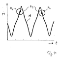
- FIG. 4 shows the typical time profile of a measurement signal M such as this.
- a higher-frequency signal is superimposed on the sinusoidal basic signal and, in this illustration, is marked with the circles K 1 and K 2 .
- the higher-frequency signal component is of particular interest for analysis of the measurement signal M, since it indicates damage in the bearing.
- the signal level of the sinusoidal basic signal M is very much higher than that of the higher-frequency signal component.
- the measurement signal M thus has to be evaluated separately in order to separate the higher-frequency signal from the basic signal component and to make it possible to unambiguously distinguish it from a noise signal which is always present and whose amplitude is often of similar magnitude.
- the measurement signal M from the measurement apparatus 8 is first of all passed to a frequency filter, which removes the undesirable frequency components from the measurement signal M.
- a frequency filter such as this can be designed such that it filters the analog or else preferably the already digitized measurement signal using appropriately preselected prior settings, and emits digital signals.
- FIG. 5 shows the result of such frequency filtering.
- the illustration shows a filtered measurement signal for a damaged roller bearing in a left-hand time period t 1 , and a filtered measurement signal for an undamaged roller bearing in the right-hand time period t 2 .
- the time t n marks the signal change from a damaged roller bearing to an undamaged roller bearing.
- the frequency filtering of the measurement signal itself results in an improvement in terms of the capability to identify higher-frequency signal components, but the ratio of the amplitudes A S of the higher-frequency measurement signal component to the amplitudes of the noise signal is still comparatively small.
- This noise component in the time period t 2 is precisely that signal profile which indicates an undamaged roller bearing, since the sinusoidal basic signal which was produced as the roller bodies 3 rolled past the respective measurement point 5 has been removed by the filtering process.
- the evaluation method according to the invention now overcomes this in that, inter alia, it creates a very much greater separation between the structure-borne sound signal and the noise signal. Furthermore, an unambiguous statement about the presence of bearing damage can be made with only a very small number of digital measurement values.
- the invention provides that a first variance value is first of all calculated from digital values of the output signal from the frequency filter (the signal profile shown in FIG. 5 ), that at least one second variance value is then determined from further digital values of the frequency filter output signal, and that the weighted arithmetic mean of these variance values is calculated from these at least two variance values (the new variance, the old variance) with the aid of a recursive calculation.
- the variance in this case, as is known, represents the square of the standard deviation, which in turn indicates how the individual measurement values are scattered about a mean value.
- a large weighted arithmetic variance mean value means that the investigated measurement signal component differs to a major extent from the sinusoidal basic signal or the noise signal, its exceeding of a predetermined variance threshold value V SW can be assessed as a structure-borne sound event which has been caused by mechanical damage to the roller bearing.
- FIG. 6 clearly shows, for a damaged roller bearing in the left-hand section of the diagram, how unusually large the separation is between the variance values V for this damaged roller bearing in a time period t 1 and the variance value for an undamaged roller bearing in a time period t 2 .
- the exceeding of the calculated variance values V in comparison to a variance threshold value V SW as shown here unambiguously indicate the presence of structure-borne sound events, and thus damage in the roller bearing.
Landscapes
- Physics & Mathematics (AREA)
- Engineering & Computer Science (AREA)
- General Engineering & Computer Science (AREA)
- Acoustics & Sound (AREA)
- General Physics & Mathematics (AREA)
- Mechanical Engineering (AREA)
- Testing Of Devices, Machine Parts, Or Other Structures Thereof (AREA)
- Rolling Contact Bearings (AREA)
- Measurement Of Mechanical Vibrations Or Ultrasonic Waves (AREA)
Abstract
A method for detecting structure-borne noise events in a roller bearing, wherein a measuring signal M of a pressure or dilatation sensor arranged on a roller bearing is fed to a frequency filter for filtering out undesired signal parts. The aim of the invention is to determine structure-borne noise waves or structure-borne noise events by an evaluation device. As a result, a first variance value is calculated from digital values of the frequency filter output signal and at least one second variance value is calculated from other digital values of the frequency filter output signal and the weighted arithmetic average of the at least two variance values (new variance, old variance) is calculated with the aid of a retrocursive calculation of the variance value. A surpassing of the weighted arithmetic variance average value (V) exceeds a pre-selected variance threshold value (vsw). It is subsequently evaluated as a structure-borne noise event provoked by mechanical damage to the roller bearing.
Description
- The invention relates to a method for detection of structure-borne sound events in a roller bearing, as claimed in the preamble of
claim 1. - DE 199 43 689 A1 discloses a method and an apparatus for monitoring and/or diagnosis of moving machines and/or machine parts. The aim of such measurement and evaluation methods is to identify damage to a machine or to a machine part such as a roller bearing as early as possible in order to make it possible to replace this item, when appropriate, before its total failure.
- In this known method, oscillations and structure-borne sound waves which are produced by the machines or machine parts are recorded by means of an acceleration sensor as a broadband time signal, and are passed to an evaluation device. The measurement signal is digitized in this evaluation device, and a relatively large range of such digital values are stored. This data is subjected to frequency analysis by means of a fast Fourier transformation in a subsequent calculation process. The process of carrying out a fast Fourier transformation such as this is highly complex and requires a comparatively large amount of computation capacity and memory space.
- Furthermore, this document discloses the broadband time signal being subjected to discrete filtering using different analysis methods.
- During this process, frequency components of the signal components caused by the damage are filtered out from the measurement signal, and an amplitude profile of this component is evaluated. Changes in the frequencies can extend the evaluation to adjacent signal components in such a way that the local amplitude maxima can be determined. The computation complexity for carrying out discrete filtering is admittedly less than that of such a conventional Fourier transformation, but it is nevertheless comparatively high since the cut-off frequencies of the filter must be dynamically matched to different rotation speeds of the shaft/bearing system.
- Finally, DE 101 36 438 A1 has disclosed a sensor arrangement in which strain gauges are arranged in a circumferential groove in a stationary roller bearing ring, where they are connected to signal-electronic modules, by means of which a signal evaluation process can be carried out directly in the circumferential groove in the roller bearing ring. Since this circumferential groove is comparatively small, the signal-electronic modules which are arranged there may have only a quite modest storage and computation capacity, so that the evaluation methods described above are not carried out in situ and, so to speak “on-line”.
- Against this background, the object of the invention is to propose a method for detection of structure-borne sound waves and structure-borne sound events for a measurement apparatus which, by way of example, is arranged in a roller bearing, by means of which method the required analysis steps can be carried out directly at the point at which the measurement signals are obtained, without a large amount of computation capacity and without a large memory space requirement. A further aim is for the measurement signal from suitable sensors on the roller bearing to be converted such that it is possible to make an unambiguous statement about the actual presence of bearing damage in a better manner than in the past. A final aim is that it should be possible to carry out this method sufficiently quickly that suddenly occurring bearing damage can be detected preferably “online”, that is to say without any time delay.
- These objects are achieved by the features in the main claim, while advantageous refinements and developments of the invention can be found in the dependent claims.
- Accordingly, the method provides that, in order to detect structure-borne sound events in a roller bearing, the measurement signal from a pressure-sensitive or strain-sensitive sensor which is arranged on a roller bearing is first of all supplied to a frequency filter in order to filter out undesirable signal components. A first variance value is then calculated from the digital values of the frequency filter output signal, and at least one second variance value is determined from subsequent digital values of the frequency filter output signal. The weighted arithmetic mean of these variance values is then calculated from these at least two variance values (new variance, old variance) with the aid of a recursive calculation. If the weighted arithmetic mean value is above a preselected variance threshold value, this is assessed as a structure-borne sound event, which has been caused by mechanical damage to the roller bearing.
- In this context, the expression “recursive calculation” means that result values from a first variance calculation are included in the calculation of a second variance value. This allows consistent estimation of the structure-borne sound amplitude on the basis of only two sample values without any need to provide additional storage capacity in an evaluation device.
- The weighted arithmetic variance mean value is determined with the aid of the following basic recursive equation:
{overscore (E)}{X 2}(k+1)={overscore (E)}{X 2}(k)+C x 2 [x 2(k+1)−{overscore (E)}{X 2}(k)] (Equation 1)
where {overscore (E)}{.} represents the expected value of the weighted arithmetic mean value, k is a running variable, x is a digital sample value of the signal, and C is an adaptation constant. - With regard to the adaptation constant C, a value is provided which is less than unity and is greater than zero, and which can be calculated from the equation for the so-called adaptation rate:
t={1/C x 2−½}*T (Equation 2).
In this expression, t indicates how quickly the true variance can be determined with a tolerable error rate. - The basic recursive equation (equation 1) can be used to form a conversion equation
nE=aE+aK*(nA−aE) (Equation 3)
in which nE represents a new result value, aE represents an old result value, aK represents the adaptation constant, and nA represents a new sample value. The “new result value” is in this case the value to be calculated at any given time, while the “old result value” denotes the value calculated one sample clock period early. - This conversion equation can be converted for the evaluation process to an evaluation equation:
nV=aV+aK*(nA−aV) (Equation 4)
where nV represents the new variance, aV represents the old variance, aK represents the adaptation constant, and nA represents the new sample value. - A new variance calculated in this way is assessed as an estimated value for the true variance of the measurement signal from which the presence of structure-borne sound events in the roller bearing is deduced. In this case, a high new variance value represents major damage in the roller bearing.
- As is evident from the above statements, the method according to the invention can be used to detect the presence of structure-borne sound waves and structure-borne sound events from a measurement apparatus that is arranged in a roller bearing, by means of an evaluation device which does not have a large memory space and has quite a small computation capacity. Evaluation devices such as these may be microcomputers which are arranged directly at the point at which the measurement signal is obtained, for example in the circumferential groove in a roller bearing, and which carry out the necessary analysis steps in order to detect bearing damage.
- Furthermore, the method according to the invention allows the measurement signal from a suitable sensor, such as a strain gauge, on the roller bearing, to be converted such that an unambiguous statement about the actual presence of bearing damage is possible in a better manner than with previously known methods. Finally, the method makes it possible to identify structure-borne sound waves using only a small number of measurement values sufficiently quickly that suddenly occurring bearing damage can be detected preferably “on-line”, that is to say without any time delay.
- The method according to the invention, its interaction with a measurement roller bearing and an evaluation device can best be explained on the basis of exemplary embodiments of the invention, which are illustrated in a drawing, in which:
-
FIG. 1 shows a schematic cross section through a measurement roller bearing, -
FIG. 2 shows a plan view of a measurement arrangement in a circumferential groove in the measurement roller bearing shown inFIG. 1 , -
FIG. 3 shows an electrical measurement bridge circuit for the measurement arrangement shown inFIG. 2 , -
FIG. 4 shows a measurement signal profile with frequency components which indicate damage in the roller bearing, -
FIG. 5 shows two measurement signals after passing through a frequency filter, and -
FIG. 6 shows the illustration of the variance mean values for the two measurement signals shown inFIG. 5 . -
FIG. 1 accordingly shows a schematic cross-section illustration through a roller bearing in whichroller bodies 3 are arranged between a stationaryouter ring 1 and aninner ring 2 which can rotate, such that theinner ring 2 is mounted, for example, such that it can rotate in adirection 6. Thisinner ring 2 is used to hold a component that is not illustrated here but which exerts a force F on theinner ring 2. As can be seen from this illustration, the force F acts via theinner ring 2 and theroller bodies 3 on theouter ring 1, such that theroller bodies 3 produce a periodic deformation, which can be measured by suitable sensors, at their moving contact points on theouter ring 1. - Measurement resistors R1, R2, R3, R4 are thus attached to the circumferential surface of the
outer ring 1 in ameasurement area 5, which resistors change their electrical resistance as a function of strain and by means of which the deformation of theouter ring 1 can thus be detected as theroller bodies 3 roll over each measurement resistor R1, R2, R3, R4. One important factor in this context, however, is that, in terms of the distances between them, the resistors R1, R2, R3, R4 must not be separately aligned. - As can be seen from
FIG. 2 , the measurement resistors R1, R2, R3, R4 in this exemplary embodiment of the measurement roller bearing are arranged in acircumferential groove 4 in theouter ring 1 in anattachment area 7 such that they are positioned parallel to the axis of the movement direction of theinner ring 1. The resistors R1, R2, R3, R4 are in this case connected to one another to form ameasurement bridge 8, whose circuit layout is illustrated inFIG. 3 . Thismeasurement bridge 8 has a voltage U applied to it in a manner known per se, and produces a largely sinusoidal measurement signal M via the contact points. This measurement signal M can be supplied to anevaluation device 9, which may be fitted in thegroove 4 in the bearing outer ring, via conductor tracks which are not illustrated here, and in which signal analysis may be carried out. -
FIG. 4 shows the typical time profile of a measurement signal M such as this. As can be seen from the signal profile, a higher-frequency signal is superimposed on the sinusoidal basic signal and, in this illustration, is marked with the circles K1 and K2. The higher-frequency signal component is of particular interest for analysis of the measurement signal M, since it indicates damage in the bearing. - Unfortunately, in the case of measurement signals such as these, the signal level of the sinusoidal basic signal M is very much higher than that of the higher-frequency signal component. The measurement signal M thus has to be evaluated separately in order to separate the higher-frequency signal from the basic signal component and to make it possible to unambiguously distinguish it from a noise signal which is always present and whose amplitude is often of similar magnitude. For this purpose, the measurement signal M from the
measurement apparatus 8 is first of all passed to a frequency filter, which removes the undesirable frequency components from the measurement signal M. A frequency filter such as this can be designed such that it filters the analog or else preferably the already digitized measurement signal using appropriately preselected prior settings, and emits digital signals. -
FIG. 5 shows the result of such frequency filtering. In this case, the illustration shows a filtered measurement signal for a damaged roller bearing in a left-hand time period t1, and a filtered measurement signal for an undamaged roller bearing in the right-hand time period t2. The time tn marks the signal change from a damaged roller bearing to an undamaged roller bearing. As can clearly be seen from this illustration, the frequency filtering of the measurement signal itself results in an improvement in terms of the capability to identify higher-frequency signal components, but the ratio of the amplitudes AS of the higher-frequency measurement signal component to the amplitudes of the noise signal is still comparatively small. This noise component in the time period t2 is precisely that signal profile which indicates an undamaged roller bearing, since the sinusoidal basic signal which was produced as theroller bodies 3 rolled past therespective measurement point 5 has been removed by the filtering process. - Since this noise separation is very small, the detection sensitivity for bearing damage that is to be detected is initially also comparatively poor. The evaluation method according to the invention now overcomes this in that, inter alia, it creates a very much greater separation between the structure-borne sound signal and the noise signal. Furthermore, an unambiguous statement about the presence of bearing damage can be made with only a very small number of digital measurement values.
- For this purpose, the invention provides that a first variance value is first of all calculated from digital values of the output signal from the frequency filter (the signal profile shown in
FIG. 5 ), that at least one second variance value is then determined from further digital values of the frequency filter output signal, and that the weighted arithmetic mean of these variance values is calculated from these at least two variance values (the new variance, the old variance) with the aid of a recursive calculation. The variance in this case, as is known, represents the square of the standard deviation, which in turn indicates how the individual measurement values are scattered about a mean value. - Since a large weighted arithmetic variance mean value means that the investigated measurement signal component differs to a major extent from the sinusoidal basic signal or the noise signal, its exceeding of a predetermined variance threshold value VSW can be assessed as a structure-borne sound event which has been caused by mechanical damage to the roller bearing.
-
FIG. 6 clearly shows, for a damaged roller bearing in the left-hand section of the diagram, how unusually large the separation is between the variance values V for this damaged roller bearing in a time period t1 and the variance value for an undamaged roller bearing in a time period t2. As can likewise be seen from this illustration, the exceeding of the calculated variance values V in comparison to a variance threshold value VSW as shown here unambiguously indicate the presence of structure-borne sound events, and thus damage in the roller bearing. -
- 1 Outer ring
- 2 Inner ring
- 3 Roller body
- 4 Groove
- 5 Measurement range
- 6 Rotation direction
- 7 Attachment area
- 8 Measurement bridge
- 9 Evaluation device
- AS Amplitude of the measurement signal S
- AF Amplitude of the filter signal
- K1 Structure-borne sound event
- K2 Structure-borne sound event
- M Measurement signal
- R1 Electrical resistor
- R2 Electrical resistor
- R3 Electrical resistor
- R4 Electrical resistor
- t Time
- t1 Time period
- t2 Time period
- tn Measurement signal change time
- V Variance
- VSW Variance threshold value
Claims (9)
1. A method for detecting structure-borne sound events in a roller bearing, comprising
supplying a measurement signal (M) from a pressure-sensitive or strain-sensitive sensor which is arranged on a roller bearing to a frequency filter for filtering out undesirable signal components;
calculating a first variance value from digital values of the frequency filter output signal;
determining at least one second variance value from further digital values of the frequency filter output signal;
calculating a weighted arithmetic mean of the first and second variance values from the at least two variance values using a recursive calculation, and
assessing any exceeding of the weighted arithmetic variance mean value above a preselected variance threshold value (VSW) as a structure-borne sound event which has been caused by mechanical damage to the roller bearing, and the frequency for exceeding the threshold can be associated with the point of origin of the damage in the bearing when a rotation speed and geometric conditions of the bearing are known.
2. The method as claimed in claim 1 , comprising calculating the weighted arithmetic mean of the variance values using the basic recursive equation:
{overscore (E)}{X 2}(k+1)={overscore (E)}{X 2}(k)=C x 2 [X 2(k+1)−{overscore (E)}{X 2}(k)] (Equation 1)
where {overscore (E)}{.} represents the expected value of the weighted arithmetic mean value, k is a running variable, x is a digital sample value of the signal, and C is an adaptation constant.
3. The method as claimed in claim 2 , wherein the adaptation constant C has a value which is less than unity and greater than zero.
4. The method as claimed in claim 3 , wherein the adaptation constant C can be calculated from an equation for the adaptation rate
t={1/C x 2−½}*T (Equation 2)
where t indicates how quickly the true variance can be determined with a tolerable error rate.
5. The method as claimed in claim 2 , wherein the basic recursive equation (equation 1) is converted to a conversion equation
nE=aE+aK*(nA−aE) (Equation 3)
in which nE represents a new result value, aE represents an old result value, aK represents the adaptation constant, and nA represents a new sample value.
6. The method as claimed in claim 5 , further comprising converting the conversion equation to an evaluation equation
nV=aV+aK*(nA−aV) (Equation 4)
where nV represents the new variance, aV represents the old variance, aK represents the adaptation constant, and nA represents a new sample value.
7. The method as claimed in claim 6 , further comprising assessing the value of the new variance as an estimated value of the true variance of the measurement signal, which marks the presence of structure-borne sound events in the roller bearing.
8. The method as claimed in claim 6 , wherein a high new variance value represents a high probability of the presence of structure-borne sound events in the roller bearing.
9. The method as claimed in claim 6 , wherein a high new variance value represents major damage in the roller bearing.
Applications Claiming Priority (3)
| Application Number | Priority Date | Filing Date | Title |
|---|---|---|---|
| DE10303877A DE10303877A1 (en) | 2003-01-31 | 2003-01-31 | Method for determining structure-borne noise events in a rolling bearing |
| DE10303877.9 | 2003-01-31 | ||
| PCT/DE2004/000095 WO2004068100A1 (en) | 2003-01-31 | 2004-01-23 | Method for detecting structure-borne noise events in a roller bearing |
Publications (2)
| Publication Number | Publication Date |
|---|---|
| US20060150737A1 true US20060150737A1 (en) | 2006-07-13 |
| US7599804B2 US7599804B2 (en) | 2009-10-06 |
Family
ID=32695104
Family Applications (1)
| Application Number | Title | Priority Date | Filing Date |
|---|---|---|---|
| US10/543,844 Expired - Fee Related US7599804B2 (en) | 2003-01-31 | 2004-01-23 | Method for detecting structure-borne noise events in a roller bearing |
Country Status (7)
| Country | Link |
|---|---|
| US (1) | US7599804B2 (en) |
| EP (1) | EP1616163B1 (en) |
| JP (1) | JP4424515B2 (en) |
| CN (1) | CN100510678C (en) |
| DE (2) | DE10303877A1 (en) |
| ES (1) | ES2277234T3 (en) |
| WO (1) | WO2004068100A1 (en) |
Cited By (4)
| Publication number | Priority date | Publication date | Assignee | Title |
|---|---|---|---|---|
| US8695405B2 (en) * | 2010-09-17 | 2014-04-15 | Bestsens Ag | Bearing, arrangement for determining properties of a lubricant in a bearing and method for determining properties of a lubricant in a bearing |
| CN113607272A (en) * | 2021-07-30 | 2021-11-05 | 清华大学 | Method and system for monitoring working state of rolling machine |
| CN116818914A (en) * | 2023-08-30 | 2023-09-29 | 东光县津东玻璃工艺制品有限公司 | Glass and nondestructive testing method for processed product thereof |
| US11994445B2 (en) | 2018-04-11 | 2024-05-28 | Zf Friedrichshafen Ag | Condition monitoring for plain bearings by means of structure-borne noise |
Families Citing this family (15)
| Publication number | Priority date | Publication date | Assignee | Title |
|---|---|---|---|---|
| US7155973B2 (en) * | 2003-07-08 | 2007-01-02 | Stephen William Dyer | Method and apparatus for balancing |
| DE102004054974B4 (en) * | 2004-11-13 | 2015-04-02 | Schaeffler Technologies AG & Co. KG | rotary joint |
| DE102005003983B4 (en) * | 2005-01-28 | 2008-07-17 | Lohmann & Stolterfoht Gmbh | Planetary gear with means for the early detection of damage to one of the rolling bearings |
| DE102007052426A1 (en) | 2007-11-02 | 2009-05-07 | Schaeffler Kg | Device for transmitting data of piezoelectric sensor from inner side of e.g. slide bearing, to receiving device, has signal converter converting collected signal into sound transmitted as solid-borne sound into body part of ring |
| DE102010012915A1 (en) * | 2010-03-26 | 2011-09-29 | Schaeffler Technologies Gmbh & Co. Kg | Device and method for determining a damage state of a wheel bearing |
| CN102519726B (en) * | 2011-12-28 | 2015-06-03 | 昆明理工大学 | Acoustic-based diagnosis (ABD) method for compound fault of rolling bearing |
| DE102015208444B4 (en) * | 2015-05-06 | 2023-04-20 | Aktiebolaget Skf | Sensor arrangement for detecting a strain, load, temperature, vibration and/or direction of movement of at least one rolling body and a roller bearing with the sensor arrangement |
| CN106595540B (en) * | 2016-12-15 | 2019-04-23 | 贵州虹轴轴承有限公司 | A device for detecting the surface smoothness of bearing balls based on sound waves |
| WO2018217794A1 (en) * | 2017-05-22 | 2018-11-29 | Waukesha Bearings Corporation | Bearing monitoring/analysis system |
| ES2843174T3 (en) * | 2017-06-12 | 2021-07-16 | Tetra Laval Holdings & Finance | Method of predicting failure of a component of a machine that moves cyclically |
| DE102017123474A1 (en) | 2017-10-10 | 2019-04-11 | Schaeffler Technologies AG & Co. KG | Method for detecting bearing damage and bearing arrangement |
| CN110723522A (en) * | 2019-10-08 | 2020-01-24 | 宁波更大集团有限公司 | Bearing noise detection device |
| DE102021211493A1 (en) * | 2021-10-12 | 2023-04-13 | Aktiebolaget Skf | Device and method for estimating a load in a bearing |
| CN115655712B (en) * | 2022-09-23 | 2025-04-01 | 重庆大学 | Rolling bearing outer ring contact stiffness calibration method and system based on three-point ultrasonic method |
| CN119023262B (en) * | 2024-07-16 | 2025-09-12 | 中核武汉核电运行技术股份有限公司 | A method for analyzing acoustic emission signal characteristics for rotating machinery condition monitoring |
Citations (12)
| Publication number | Priority date | Publication date | Assignee | Title |
|---|---|---|---|---|
| US5365787A (en) * | 1991-10-02 | 1994-11-22 | Monitoring Technology Corp. | Noninvasive method and apparatus for determining resonance information for rotating machinery components and for anticipating component failure from changes therein |
| US5602761A (en) * | 1993-12-30 | 1997-02-11 | Caterpillar Inc. | Machine performance monitoring and fault classification using an exponentially weighted moving average scheme |
| US5852793A (en) * | 1997-02-18 | 1998-12-22 | Dme Corporation | Method and apparatus for predictive diagnosis of moving machine parts |
| US6208944B1 (en) * | 1997-06-26 | 2001-03-27 | Pruftechnik Dieter Busch Ag | Method for determining and displaying spectra for vibration signals |
| US20020013664A1 (en) * | 2000-06-19 | 2002-01-31 | Jens Strackeljan | Rotating equipment diagnostic system and adaptive controller |
| US6567752B2 (en) * | 2000-08-15 | 2003-05-20 | The Penn State Research Foundation | General method for tracking the evolution of hidden damage or other unwanted changes in machinery components and predicting remaining useful life |
| US6883373B2 (en) * | 1999-03-31 | 2005-04-26 | Stephen William Dyer | Method and apparatus for balancing |
| US6889553B2 (en) * | 2003-07-16 | 2005-05-10 | Pcb Piezotronics Inc. | Method and apparatus for vibration sensing and analysis |
| US6999884B2 (en) * | 2003-01-10 | 2006-02-14 | Oxford Biosignals Limited | Bearing anomaly detection and location |
| US7039557B2 (en) * | 2001-09-07 | 2006-05-02 | Daimlerchrysler Ag | Device and method for the early recognition and prediction of unit damage |
| US20060110086A1 (en) * | 2000-12-01 | 2006-05-25 | Nsk Ltd. | Sensor and rollling bearing apparatus with sensor |
| US7136794B1 (en) * | 2001-05-24 | 2006-11-14 | Simmonds Precision Products, Inc. | Method and apparatus for estimating values for condition indicators |
Family Cites Families (7)
| Publication number | Priority date | Publication date | Assignee | Title |
|---|---|---|---|---|
| GB1514792A (en) * | 1974-07-12 | 1978-06-21 | Nippon Seiko Kk | Device for detecting damage to rotators |
| JPH065194B2 (en) * | 1987-06-03 | 1994-01-19 | 光洋精工株式会社 | Collision detection device for roller bearings in which roller is in sliding contact with flange |
| DE19612180C1 (en) * | 1996-03-27 | 1997-03-06 | Siemens Ag | Irregular combustion detection method for multicylinder diesel engine |
| IT1293410B1 (en) * | 1997-07-04 | 1999-03-01 | Finmeccanica Spa | METHOD OF SURVEILLANCE OF A TRANSMISSION UNIT IN A VEHICLE EQUIPPED WITH ACCELEROMETRIC SENSORS, ESPECIALLY IN A HELICOPTER. |
| DE19902326C2 (en) * | 1999-01-21 | 2003-05-08 | Medav Digitale Signalverarbeit | Process for early damage detection of rotating machines |
| DE19943689A1 (en) | 1999-09-06 | 2001-03-08 | Busch Dieter & Co Prueftech | Method and device for monitoring and / or diagnosing moving machines and / or machine parts |
| DE10136438A1 (en) | 2000-08-22 | 2002-03-07 | Bosch Gmbh Robert | Sensor arrangement for direct measurement of forces and moments acting on bearing box and derivation from these of other values useful in automatic vehicle control systems |
-
2003
- 2003-01-31 DE DE10303877A patent/DE10303877A1/en not_active Withdrawn
-
2004
- 2004-01-23 EP EP04704535A patent/EP1616163B1/en not_active Expired - Lifetime
- 2004-01-23 CN CNB2004800030853A patent/CN100510678C/en not_active Expired - Fee Related
- 2004-01-23 US US10/543,844 patent/US7599804B2/en not_active Expired - Fee Related
- 2004-01-23 DE DE502004002624T patent/DE502004002624D1/en not_active Expired - Fee Related
- 2004-01-23 ES ES04704535T patent/ES2277234T3/en not_active Expired - Lifetime
- 2004-01-23 JP JP2006501468A patent/JP4424515B2/en not_active Expired - Fee Related
- 2004-01-23 WO PCT/DE2004/000095 patent/WO2004068100A1/en not_active Ceased
Patent Citations (12)
| Publication number | Priority date | Publication date | Assignee | Title |
|---|---|---|---|---|
| US5365787A (en) * | 1991-10-02 | 1994-11-22 | Monitoring Technology Corp. | Noninvasive method and apparatus for determining resonance information for rotating machinery components and for anticipating component failure from changes therein |
| US5602761A (en) * | 1993-12-30 | 1997-02-11 | Caterpillar Inc. | Machine performance monitoring and fault classification using an exponentially weighted moving average scheme |
| US5852793A (en) * | 1997-02-18 | 1998-12-22 | Dme Corporation | Method and apparatus for predictive diagnosis of moving machine parts |
| US6208944B1 (en) * | 1997-06-26 | 2001-03-27 | Pruftechnik Dieter Busch Ag | Method for determining and displaying spectra for vibration signals |
| US6883373B2 (en) * | 1999-03-31 | 2005-04-26 | Stephen William Dyer | Method and apparatus for balancing |
| US20020013664A1 (en) * | 2000-06-19 | 2002-01-31 | Jens Strackeljan | Rotating equipment diagnostic system and adaptive controller |
| US6567752B2 (en) * | 2000-08-15 | 2003-05-20 | The Penn State Research Foundation | General method for tracking the evolution of hidden damage or other unwanted changes in machinery components and predicting remaining useful life |
| US20060110086A1 (en) * | 2000-12-01 | 2006-05-25 | Nsk Ltd. | Sensor and rollling bearing apparatus with sensor |
| US7136794B1 (en) * | 2001-05-24 | 2006-11-14 | Simmonds Precision Products, Inc. | Method and apparatus for estimating values for condition indicators |
| US7039557B2 (en) * | 2001-09-07 | 2006-05-02 | Daimlerchrysler Ag | Device and method for the early recognition and prediction of unit damage |
| US6999884B2 (en) * | 2003-01-10 | 2006-02-14 | Oxford Biosignals Limited | Bearing anomaly detection and location |
| US6889553B2 (en) * | 2003-07-16 | 2005-05-10 | Pcb Piezotronics Inc. | Method and apparatus for vibration sensing and analysis |
Cited By (4)
| Publication number | Priority date | Publication date | Assignee | Title |
|---|---|---|---|---|
| US8695405B2 (en) * | 2010-09-17 | 2014-04-15 | Bestsens Ag | Bearing, arrangement for determining properties of a lubricant in a bearing and method for determining properties of a lubricant in a bearing |
| US11994445B2 (en) | 2018-04-11 | 2024-05-28 | Zf Friedrichshafen Ag | Condition monitoring for plain bearings by means of structure-borne noise |
| CN113607272A (en) * | 2021-07-30 | 2021-11-05 | 清华大学 | Method and system for monitoring working state of rolling machine |
| CN116818914A (en) * | 2023-08-30 | 2023-09-29 | 东光县津东玻璃工艺制品有限公司 | Glass and nondestructive testing method for processed product thereof |
Also Published As
| Publication number | Publication date |
|---|---|
| DE502004002624D1 (en) | 2007-02-22 |
| EP1616163A1 (en) | 2006-01-18 |
| CN100510678C (en) | 2009-07-08 |
| JP2006518455A (en) | 2006-08-10 |
| ES2277234T3 (en) | 2007-07-01 |
| EP1616163B1 (en) | 2007-01-10 |
| WO2004068100A1 (en) | 2004-08-12 |
| CN1756944A (en) | 2006-04-05 |
| DE10303877A1 (en) | 2004-08-12 |
| JP4424515B2 (en) | 2010-03-03 |
| US7599804B2 (en) | 2009-10-06 |
Similar Documents
| Publication | Publication Date | Title |
|---|---|---|
| US7599804B2 (en) | Method for detecting structure-borne noise events in a roller bearing | |
| CN203432784U (en) | State monitoring device used for rotary mechanical components | |
| US7822580B2 (en) | Method and a system for monitoring the condition and operation of periodically moving objects | |
| JPS6219755A (en) | AE type rotating machine abnormality diagnosis system | |
| JPH05284689A (en) | Adjustment support device for rotating body connection | |
| JP2001304954A (en) | Failure diagnosis method and device | |
| Kerst et al. | A model-based approach for the estimation of bearing forces and moments using outer ring deformation | |
| EP3601990B1 (en) | A bearing monitoring method and system | |
| JPH1026580A (en) | Diagnosis method and apparatus for variable speed rotary machine equipment | |
| Vogl et al. | A defect-driven diagnostic method for machine tool spindles | |
| De Almeida et al. | New technique for evaluation of global vibration levels in rolling bearings | |
| JP7082585B2 (en) | Bearing information analysis device and bearing information analysis method | |
| GB2383635A (en) | Chromatic analysis of measured acoustic signals from a system | |
| JPH0588774B2 (en) | ||
| CN112664379A (en) | Method and device for prejudging faults of water turbine set | |
| US7650254B2 (en) | Method for the detection and quantitative evaluation of a balance error in a shaft-bearing system | |
| EP2110649B1 (en) | Sensor for surveying mechanical construction parts | |
| US10914656B2 (en) | Condition monitoring | |
| US7152476B2 (en) | Measurement of motions of rotating shafts using non-vibrating contact potential difference sensor | |
| KR20240087978A (en) | A method of gathering vibration frequency and cutting load of spindle motor in the cnc machine | |
| US6347548B1 (en) | Apparatus for and method of monitoring a rotating machine | |
| Meier et al. | Determination of bearing clearance by the application of neural networks | |
| JP4912017B2 (en) | Rolling bearing runout signal analyzer and rolling bearing production system | |
| Patidar et al. | Study of detection of defects in rolling element bearings using vibration and acoustic measurement methods-A Review | |
| Shao et al. | Bearing fault diagnosis based on embedded multiple sensors |
Legal Events
| Date | Code | Title | Description |
|---|---|---|---|
| REMI | Maintenance fee reminder mailed | ||
| LAPS | Lapse for failure to pay maintenance fees | ||
| STCH | Information on status: patent discontinuation |
Free format text: PATENT EXPIRED DUE TO NONPAYMENT OF MAINTENANCE FEES UNDER 37 CFR 1.362 |
|
| STCH | Information on status: patent discontinuation |
Free format text: PATENT EXPIRED DUE TO NONPAYMENT OF MAINTENANCE FEES UNDER 37 CFR 1.362 |
|
| FP | Lapsed due to failure to pay maintenance fee |
Effective date: 20131006 |