US6883373B2 - Method and apparatus for balancing - Google Patents
Method and apparatus for balancing Download PDFInfo
- Publication number
- US6883373B2 US6883373B2 US10/615,076 US61507603A US6883373B2 US 6883373 B2 US6883373 B2 US 6883373B2 US 61507603 A US61507603 A US 61507603A US 6883373 B2 US6883373 B2 US 6883373B2
- Authority
- US
- United States
- Prior art keywords
- control
- influence coefficient
- balancer
- vibration
- balance
- Prior art date
- Legal status (The legal status is an assumption and is not a legal conclusion. Google has not performed a legal analysis and makes no representation as to the accuracy of the status listed.)
- Expired - Lifetime
Links
- 238000000034 method Methods 0.000 title claims description 42
- 230000003044 adaptive effect Effects 0.000 claims description 111
- 238000012937 correction Methods 0.000 claims description 82
- 230000001965 increasing effect Effects 0.000 claims description 10
- 238000005520 cutting process Methods 0.000 claims description 7
- 230000003247 decreasing effect Effects 0.000 claims description 4
- 238000012935 Averaging Methods 0.000 claims description 3
- 238000009826 distribution Methods 0.000 claims description 3
- 239000011159 matrix material Substances 0.000 description 92
- 239000013598 vector Substances 0.000 description 42
- 238000012360 testing method Methods 0.000 description 34
- 230000004044 response Effects 0.000 description 30
- 230000008859 change Effects 0.000 description 29
- 238000005259 measurement Methods 0.000 description 23
- 230000006870 function Effects 0.000 description 18
- 230000001360 synchronised effect Effects 0.000 description 18
- 238000013459 approach Methods 0.000 description 12
- 230000000694 effects Effects 0.000 description 12
- 238000002474 experimental method Methods 0.000 description 9
- 230000008901 benefit Effects 0.000 description 7
- 230000005284 excitation Effects 0.000 description 7
- 238000003754 machining Methods 0.000 description 6
- 230000000712 assembly Effects 0.000 description 5
- 238000000429 assembly Methods 0.000 description 5
- 238000011217 control strategy Methods 0.000 description 5
- 230000035945 sensitivity Effects 0.000 description 5
- 238000004458 analytical method Methods 0.000 description 4
- 230000000052 comparative effect Effects 0.000 description 4
- 230000009172 bursting Effects 0.000 description 3
- 238000010586 diagram Methods 0.000 description 3
- 238000000227 grinding Methods 0.000 description 3
- 239000000523 sample Substances 0.000 description 3
- 230000005355 Hall effect Effects 0.000 description 2
- 230000004913 activation Effects 0.000 description 2
- 230000006978 adaptation Effects 0.000 description 2
- 238000004364 calculation method Methods 0.000 description 2
- 230000001186 cumulative effect Effects 0.000 description 2
- 239000002184 metal Substances 0.000 description 2
- 238000005312 nonlinear dynamic Methods 0.000 description 2
- 230000009022 nonlinear effect Effects 0.000 description 2
- 238000012887 quadratic function Methods 0.000 description 2
- 238000005070 sampling Methods 0.000 description 2
- 229920006395 saturated elastomer Polymers 0.000 description 2
- 238000010187 selection method Methods 0.000 description 2
- 238000007493 shaping process Methods 0.000 description 2
- 238000011144 upstream manufacturing Methods 0.000 description 2
- 230000003213 activating effect Effects 0.000 description 1
- 238000004422 calculation algorithm Methods 0.000 description 1
- 230000015556 catabolic process Effects 0.000 description 1
- 230000002301 combined effect Effects 0.000 description 1
- 238000010276 construction Methods 0.000 description 1
- 238000010924 continuous production Methods 0.000 description 1
- 238000006880 cross-coupling reaction Methods 0.000 description 1
- 238000006731 degradation reaction Methods 0.000 description 1
- 238000009795 derivation Methods 0.000 description 1
- 230000003292 diminished effect Effects 0.000 description 1
- 230000009977 dual effect Effects 0.000 description 1
- 230000002708 enhancing effect Effects 0.000 description 1
- 230000007613 environmental effect Effects 0.000 description 1
- 238000011156 evaluation Methods 0.000 description 1
- 238000001914 filtration Methods 0.000 description 1
- 238000009472 formulation Methods 0.000 description 1
- 229910000078 germane Inorganic materials 0.000 description 1
- 239000007788 liquid Substances 0.000 description 1
- 230000007774 longterm Effects 0.000 description 1
- 230000007257 malfunction Effects 0.000 description 1
- 238000004519 manufacturing process Methods 0.000 description 1
- 230000007246 mechanism Effects 0.000 description 1
- 239000000203 mixture Substances 0.000 description 1
- 238000012544 monitoring process Methods 0.000 description 1
- 230000008092 positive effect Effects 0.000 description 1
- 238000010248 power generation Methods 0.000 description 1
- 230000009467 reduction Effects 0.000 description 1
- 238000011160 research Methods 0.000 description 1
- 238000001228 spectrum Methods 0.000 description 1
- 230000006641 stabilisation Effects 0.000 description 1
- 238000011105 stabilization Methods 0.000 description 1
- 238000012549 training Methods 0.000 description 1
- 238000012546 transfer Methods 0.000 description 1
- 230000001052 transient effect Effects 0.000 description 1
Images


Classifications
-
- G—PHYSICS
- G01—MEASURING; TESTING
- G01M—TESTING STATIC OR DYNAMIC BALANCE OF MACHINES OR STRUCTURES; TESTING OF STRUCTURES OR APPARATUS, NOT OTHERWISE PROVIDED FOR
- G01M1/00—Testing static or dynamic balance of machines or structures
- G01M1/30—Compensating imbalance
- G01M1/36—Compensating imbalance by adjusting position of masses built-in the body to be tested
-
- G—PHYSICS
- G01—MEASURING; TESTING
- G01M—TESTING STATIC OR DYNAMIC BALANCE OF MACHINES OR STRUCTURES; TESTING OF STRUCTURES OR APPARATUS, NOT OTHERWISE PROVIDED FOR
- G01M1/00—Testing static or dynamic balance of machines or structures
- G01M1/14—Determining imbalance
- G01M1/16—Determining imbalance by oscillating or rotating the body to be tested
- G01M1/22—Determining imbalance by oscillating or rotating the body to be tested and converting vibrations due to imbalance into electric variables
Definitions
- This invention generally relates to a method and an apparatus for balancing and more particularly to a method and to an apparatus for balancing a rotating machine tool and/or rotating/moving machine tool assembly.
- Machine tool assemblies are used to create and/or to form various parts, products, and other types of entities and/or apparatuses.
- these apparatuses include tools which are usually and removably placed, by means of a tool holder, upon a rotating or moving spindle and which are adapted to engage a workpiece or other apparatus and to engagingly form the workpiece into a desired shape and size.
- these machine tool assemblies adequately create the desired parts, products, and/or other entities they are prone to imbalance failure and/or imbalance error.
- the precision and reliability of these relatively high-speed machine tool assemblies is limited by the imbalance which exists and/or arises as the assembly is used (e.g. as the tool is engaging rotated and/or moved against the workpiece).
- Applicant's invention addresses these needs and these aforedescribed drawbacks of these prior art balancing devices and methodologies in a new and novel fashion.
- Applicant's invention is not limited to the balancing of a machine tool assembly. Rather, Applicant's invention is directed to the balance of any moving and/or rotating member.
- a balancer is provided.
- the balancer includes a balancer to selectively balance unbalance in a rotating tool assembly; and control means, connected to the balancer, for causing said balancer to calculate an influence coefficient of the rotating tool assembly and to thereafter selectively balance the rotating tool assembly by the movement of the balancer, movement being defined by said calculated influence coefficient.
- the balancer includes a balancing means to selectively balance a rotating tool assembly; and control means, coupled to said balancing means, for dynamically calculating vibration levels necessary for said balancing to begin and to end.
- a balancer methodology includes the steps of a method of balancing a tool assembly by selectively employing a balance weight correction to said tool assembly, said method comprising the steps of employing a first balance weight correction to said tool assembly, measuring an amount of vibration associated with said balance tool assembly, estimating an influence coefficient value of said tool assembly, dividing said measured amount of vibration by said estimate influence coefficient thereby creating a certain value; multiplying said certain value by a gain parameter value, thereby creating a second certain value and subtracting said second certain value from said first balance weight correction, thereby creating a new balance weight correction and applying said new balance weight connection to said tool assembly.
- a balancer is provided which substantially reduces and/or eliminates transitory vibration increases.
- FIG. 1 is a block diagram of a balancing apparatus made and operating in accordance with the preferred embodiment of the invention and shown operatively coupled to and deployed upon a typical tool assembly.
- FIG. 2 is a graph of the vibration sensitivity of a particular spindle to maximum capacity balance correction.
- FIG. 3.1 is a graph of a single active balancing control stable for all values of the gain multiplied by the quotient of the actual and estimated influence coefficients which are falling with the unit circle in the right half complex plane.
- FIG. 3.2 is a graph of the forgetting factor with a normalized variance of influence coefficient estimate.
- FIG. 3.3 is a graph of the number of estimation iterations required for 95% convergence of the estimate for varying forgetting factor values.
- FIG. 3.4 is a schematic block diagram of an adaptive influence coefficient control system.
- FIG. 3.5 is a flow chart of experimental single plane active balancing control system.
- FIG. 3.6 is a graph of the vibration sensitivity phase angle of the particular spindle shown in FIG. 2 .
- FIG. 3.7 is a graph of the measure spindle housing vibration during active balancing of a nonlinear system.
- FIG. 3.8 is a graph of the measured time-frequency spectrum of spindle housing vibration showing broadband effect of active balancing of nonlinear systems.
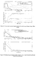
- FIG. 3.9 is a graph of measured spindle housing vibration during single-plane adaptive active balancing with an inaccurate initial influence coefficient estimate.
- FIG. 3.10 is a graph of measured spindle housing vibration during single-plane active balancing after adaptive system “learning”.
- FIG. 3.11 is a graph of measured spindle vibration before and after adaptive active balancing at various spindle speeds.
- FIG. 3.12 is a graph of the normalized magnitude and phase of blance correction required to minimize vibration at each spindle speed.
- FIG. 4.1 is a graph of simulated adaptive control response and infinite argument magnitude of equation 4.2.
- FIG. 4.2 is a graph of the automatically tuned parameter values as functions of influence coefficient estimation error.
- FIG. 4.3 is graph of the hysteresis band between the supervisory limits which reduce spurious control activation.
- FIG. 4.4 is a graph of the experimental results using automatic supervisory control limit setting with auto-tuning active balance system.
- FIG. 4.5 is a pair of graphs of spindle housing vibration during active balancing using conventional fixed parameter adaptive control and auto-tuning adaptive control with erroneous initial influence coeffiecient estimates.
- FIG. 4.6 is a collection of graphs comparing active balancing control performance of auto-timing control and conventional fixed parameter adaptive control with erroneous initial influence estimates.
- FIG. 4.7 is a pair of graphs depicting spindle housing vibration during active balancing using cautious conventional fixed-parameter adaptive control and auto-tuning adaptive control with erroneous initial influence coefficient estimates.
- FIG. 4.8 is a collection of graphs comparing active balancing control performance using cautious conventional fixed-parameter adaptive control auto-tuning with erroneous initial influence estimates.
- FIG. 4.9 is a pair of graphs depicting spindle housing vibration during active balancing using conventional adaptive control and auto-tuning adaptive control with accurate initial influence coefficient estimates.
- FIG. 4.10 is a collection of graphs comparing active balancing control performance of conventional fixed-parameter adaptive and control auto-tuning control with accurate initial influence coefficient estimates.
- FIG. 5.1 is a flow chart of supervisory adaptive optimal control for multiple-plane active balancing systems.
- FIG. 5.2 is a table of the average measured balancing influence matrix at 3,100 RPM.
- FIG. 5.3 is a graph of the predicted mode shapes of a flexible rotor test rig for two critical speeds.
- FIG. 5.4 is a graph of the predicted force response deflected shape of a rotor at 3,100 RPM due to 0.34 Oz-In. unbalance at drive-end active balancing plane.
- FIG. 5.5 is a pair of graphs comparing adaptive optimal control results using single-plane and dual plane active balancing.
- FIG. 5.6 is a pair of graphs comparing the results of adaptive optimal control with and without control effort penalty.
- FIG. 5.7 is a pair of graphs depicting the results of filly output dithered adaptive optimal control of a lightly cross-coupled system.
- FIG. 5.8 is a collection of graphs depicting the dual-plane optimal active balancing control results for a somewhat inaccurate initial influence matrix estimate.
- FIG. 5.9 is a pair of graphs depicting the objective function response and estimated stability criterion during optimal active balancing control with an erroneous initial influence matrix estimate.
- FIG. 5.10 is a collection of graphs depicting the results of non-adaptive and adaptive optimal control strategies.
- FIG. 1 there is shown a balancing assembly 10 shown in operative and assembled relation with a typical and conventional tool assembly 12 .
- Assembly 10 is made in accordance and operates in accordance with the preferred embodiment of the invention.
- tool assembly 12 includes a moving or selectively rotatable spindle 14 having an integral tool holder 16 into which a tool 18 is removably placed.
- the movement and/or rotation of spindle 14 causes the tool 18 to move and/or rotate and to engage a workpiece 20 for the purpose of “machining” the workpiece 20 into some sort of desirable shape, size, and/or geometry.
- tool assembly 12 is subject to unbalances which cause the tool 18 to perform imprecisely and undesirably and which causes the tool 18 and/or other portions of assembly 12 to fail and/or to become fatigued.
- balancer assembly 10 includes a controller 22 which in one embodiment of the invention comprises a microprocessor acting and/or operating under stored program control and an electrical driver 24 which is selectively coupled to the source of electrical power 26 through controller 22 and which is adapted to selectively couple electrical power to the balancer actuators and/or rotors 28 , 30 in a manner effective to correct a measured and/or calculated unbalance condition associated with the tool assembly 12 , by movement of these rotors 28 , 30 .
- Such unbalance measurement may be made by the use of one or more vibration sensors 32 .
- balancer assembly 10 further includes a position sensor 34 which is communicatively and operatively coupled to the controller 22 and which is adapted to provide positioning information associated with the placement and/or positioning of the rotors 28 , 30 , to the controller 22 .
- Applicant's invention is directed to the manner of moving these unbalance correction rotors or other balance correction members.
- Applicant's invention may be used with a wide variety of computerized balancing systems; each of these systems being adapted to selectively provide a balancing weight correction achieved by the movement of a certain member or members each having a certain non-symmetrical or uneven mass distribution.
- One example of such a balancing system 10 is shown for example and without limitation, within U.S. Pat. No.
- an automatic and/or substantially automatic tuning mechanism is provided which is based upon two adaptive parameters which are calculated during each control iteration based upon the convergence of the influence coefficient estimate. These parameters are used to define the correction movement of the balancer 10 and/or of those movable balancer members of the balancer assemblies in order to balance a tool assembly spindle, turbomachinery, or other moving member.
- the measured vibration of the tool assembly 12 can be considered to be an “error signal” that is desired to be eliminated by the use of an unbalance compensation apparatus, such as and without limitation balancer assembly 10 .
- vibrational data is sampled and depending upon the “level” or amount of reported unbalance, the rotors 28 , 30 are moved to a certain position. That is, vibrational data emanating from the sensor(s) 32 is communicatively coupled to the balancer controller 22 where it is “recognized” and where it causes certain balance operations to occur in order to minimize the amount of unbalance present within the tool assembly 12 .
- This “error signal” can be mathematically represented as a complex phasor having a certain phase angle (e.g. obtained by the use of a fixed target on rotating assembly which is utilized by the position sensor 34 ) and a magnitude.
- the total vibrational error signal can be thought of as the linear and mathematical summation of all of the system “disturbances” (e.g. anything of a physical or electrical nature that might cause the tool system 12 to become unbalanced, such as and without limitation a “wearing away” of a portion of the tool holder) and of the overall effect of the balance corrections which were made to the system.
- disurbances e.g. anything of a physical or electrical nature that might cause the tool system 12 to become unbalanced, such as and without limitation a “wearing away” of a portion of the tool holder
- e k C ( ⁇ ) W k +d Eq.(3.1) Where “C( ⁇ )” is the influence coefficient of the tool assembly 12 and Where “d” is the total disturbances applied to and/or resident within tool assembly 12 and where “W k ” is the balance weight correction applied to assembly 12 by the balancing assembly 10 .
- the vibrational error associated with and/or “reported”/calculated/measured at of each control iteration is the mathematical sum of all of the disturbances present during or at that particular iteration and the mathematical multiplicative product of the balance correction made during that interval with the influence coefficient of the machine.
- the influence coefficient “C( ⁇ )” is a measure of the total response of assembly 12 to a certain amount of unbalance correction and is calculated and/or estimated in measurement units of units of vibration per unit of unbalance.
- the metric “C( ⁇ )” defines and/or is a measure of the response of the system 12 to a certain amount of applied unbalance compensation and is a transfer function.
- the value of this influence coefficient may change.
- ⁇ is an estimate of the actual influence coefficient c.
- This gain parameter ⁇ can improve control robustness to errors in the influence estimate ⁇ .
- We can, without loss of generality, consider the disturbance d to be represented by the influence of a hypothetical unbalance u (which may include any synchronous forcing, not just unbalance) acting through some cumulative influence coefficient c u such that d cc u u Eq.
- v k w k +c u u Eq.(3.6)
- This criterion can be represented graphically in the complex plane as shown in FIG. 3.1 .
- ⁇ is defined to be greater than zero, if the phase angle of the influence coefficient estimate lies between ⁇ 90° (noninclusive) of the actual influence coefficient phase angle (i.e., the real part of the quotient c/ ⁇ is greater than zero), then there exists a gain ⁇ for which the control is stable.
- the forgetting factor ⁇ can be chosen to provide an optimum trade-off between estimation sensitivity to measurement noise, and speed of estimation convergence.
- the estimation variance can be reduced by selecting a low value for ⁇ .
- the estimation variance approaches the variance of the calculated parameter c new . This relationship is shown in FIG. 3.2 .
- the estimation will “track” the actual influence coefficient c as it varies over time.
- the disadvantage of choosing a low forgetting factor ⁇ is that estimation convergence rate is reduced.
- the block diagram form of the controller is shown in FIG. 3.4 .
- the supervisory strategy used for these experiments was to “turn off” the estimation whenever the change in control vectors w k ⁇ w k ⁇ 1 fell below some predetermined low level. This level was chosen base on the balance correction resolution and measurement noise of the balance correction vector.
- the control was deactivated whenever the vibration error level fell below a preset limit. When deactivated, the controller could continue to monitor the vibration error and reactivate the control and estimation when the error exceeded a certain limit.
- the limit level included some “hysteresis” to prevent annoying on-off cycles of the controller.
- the vibration error limit at which the controller was somewhat higher than the limit at which the controller turned off.
- a flow chart of this supervisory strategy is shown in FIG. 3.5 .
- Such a supervisory control strategy is important for machine tool applications as active balance corrections should only be performed prior to, not during, metal cutting.
- the balancing system was configured so that it could receive an “activate” command, and after successful control of vibration error below the limit level, would deactivate itself. Vibration error, would be monitored continuously for history logging purposes.
- Test spindle 1 was a 23,700 rpm, 1 kW air-cooled spindle.
- Test spindle 2 was a 15,000 rpm, 75 kW liquid-cooled spindle.
- a Hall Effect sensor detected a fixed magnetic target on the rotating shaft to compute spindle rotational speed and to act as a phase reference.
- the synchronous vibration error phasor was computed each control iteration as discussed previously. Thirty-two (32), samples of spindle housing radial vibration (measured with a piezoelectric accelerometer) were obtained every spindle revolution with sampling synchronized to spindle rotation. Data from multiple spindle revolutions (typically six) were then time-synchronous averaged to provide additional filtering of noise and non-synchronous components.
- Balance correction was measured by detecting the passing of a magnet target on each balance rotor by stationary Hall Effect sensors. The phase lag of these events compared to the shaft phase reference target was calculated to determine the angular location of each balance rotor.
- Test spindle 1 was used to test the adaptive control system robustness in the presence of nonlinear dynamics.
- the spindle exhibited a “hardening” stiffness effect when vibrating at large amplitudes.
- the spindle dynamic stiffness was about two times greater at high unbalance levels than at low unbalance levels. For example, on unit of unbalance would cause on unit of vibration, but two units of unbalance would result in only about 1.5 units of vibration.
- a non-adaptive linear influence coefficient based control algorithm generally may have difficulty quickly achieving low vibration in the presence of such a harsh nonlinearity. Control stability may also be in question depending on the initial conditions. For the test described here, an initial estimate of the influence coefficient magnitude and phase in the range of previously measured varying values was supplied to the controller.
- FIG. 3.7 shows how the measured spindle housing vibration at the operating speed 10,000 rpm was reduced to an acceptable level by the adaptive controller.
- FIG. 3.7 shows that vibration was controlled to below the low limit in two balance correction iterations the time required for the vibration data sampling, estimation, and control computation is evident by noting the time between the end of the first balance iteration and the start of the second (observable when the vibration again begins to decrease again just before one second). A portion of this time between balance weight positioning was allotted as a fixed delay to allow the transient vibration to settle.
- the erroneous initial influence coefficient estimate caused the controller to move the balance weights in the “wrong” direction, causing undesired temporary increase in vibration which could have permanently harmed the tool assembly.
- new input-output data was utilized in a weighted average to re-estimate the system unbalance response vector.
- the active balancing system controlled vibration to below the preset low limit. The controller then had acquired, or “learned”, the spindle dynamic response at that operating speed during the exercising of control.
- the active balancing system can be used as a probe to measure and track the inherent dynamic response of a system.
- Such data contains useful diagnostic information such as and without limitation data associated with the dynamic bearing stiffness and effective rotating inertia.
- test results shown in FIG. 3.10 indicate how quickly the single-plane control system can respond when an accurate estimate of the influence coefficient vector is available.
- a test of the active balancing system on test spindle 2 resulted in significantly decreased vibration at all speeds.
- the spindle was run at various constant speeds from 5,000 rpm up to its maximum operating speed of 15,000 rpm and active balancing at each speed and is shown in FIG. 3.11 .
- the spindle manufacturer considered 2 mm/sec to be acceptable but less than 1 mm/sec vibration desirable to protect spindle bearing life.
- the adaptive active balancing system reduced synchronous vibration by 79-99%.
- the control system was able to maintain synchronous vibration at or below 0.5 mm/sec even when initial vibration well exceeded acceptable levels.
- Background vibration “noise” and the positioning resolution of the balance mass actuators determined the minimum achievable controlled vibration level.
- the balance correction states providing minimal synchronous vibration at each speed during the tests are shown in FIG. 3.12 .
- the amount the balance correction magnitude and phase had to change over the speed range is a measure of how “upstream”, or co-located, the vibration control was. If the optimal balance correction remained the same over the entire speed range, we would know that the balance correction was exciting the same vibrational modes as the disturbance unbalance. In this case the control input would be entering the system in the same way as the disturbance and the control could be considered to be eliminating the source of harmful vibration. If the balance correction were required to change significantly over the speed range it would be evidence of more “downstream” or non-colocated control. That is, the control would be exciting different vibrational modes than the disturbance unbalance. The control, therefore, could only eliminate the effect of the disturbance at the sensor, not the disturbance itself.
- a significantly useful side benefit of the active balancing system is that it can be used as a probe to measure and track the unbalance response of a system.
- Such system identification information contains useful data about the dynamic bearing stiffness and effective rotating mass.
- the unbalance sensitivity was stored at each speed every time the active balancing system was enabled to control vibration. This data was obtained for two spindle system configurations to allow for comparisons. A long tool and short tool were separately inserted into the spindle and active balancing control enabled for successive rotational speeds.
- FIG. 2 and FIG. 3.6 show the measured unbalance sensitivity amplitude and phase angle for the two tool configurations.
- the single plane adaptive influence coefficient recursive control law was earlier derived.
- the controller 10 commands the balance correction at control iteration k+1 to the state given in Eq. (3.17) by the use of “ ⁇ ” and “ ⁇ ” control parameters. The manner in which this is accomplished is further shown below.
- the overall adaptively controlled error response can be derived.
- Such a scenario is representative of the typical machine tool active balancing application. After each tool change, balancing is performed at the new operating speed at which cutting is to be performed.
- the relevant dynamics can, in general, be expected to vary significantly from tool change to tool change because of different spindle operating speeds, toolholder inertias, and geometric configurations of the machine structure. However once the spindle is accelerated to the new operating speed, the unbalance disturbance and machine dynamics do not typically change during the few seconds in which active balancing is performed.
- the adaptively controlled vibration error response can be formulated using the control and estimation equations previously derived. This formulation is based on the assumptions that the actual influence coefficient c and unbalance disturbance d do not change during control convergence, and that “sufficient excitation” exists to allow non-singular estimation at each control iteration. When the control has converged well enough that the balance correction is no longer changing, the estimation must be “turned off”. After such convergence the active balancing control response will be the same as non-adaptive control method. To analyze the control response during convergence, we can substitute the expected value of the influence coefficient estimate from Eq.(3.16) into the control of law Eq.(3.17).
- the stability analysis above is based on the assumption that neither the unbalance disturbance nor the machine dynamics changed during control convergence. However, it is reasonable to extend the stability conclusion to certain cases of time-varying disturbances and influence coefficients. Simplistically speaking, after initial convergence, the on-line estimation would “track” changes in the machine dynamics with exponential convergence as long as the influence coefficient varied less than 2 ⁇ times the previous influence coefficient each control iteration. This is because the estimation will respond a fraction ⁇ times the distance to the actual value during each iteration. Similarly, if the unbalance disturbance changes less than 2 ⁇ times the previous value during each iteration, the control would still exhibit exponential convergence because the control would get closer to the optimal value each iteration.
- Eq. (4.7) and Eq. (4.8) ensure that when the influence estimation error is high, the control gain ⁇ k is low. Examples of acceptable scaling factors include the value of 1 for each factor.
- ⁇ k is given by Eq.(4.7) and ⁇ k is computed from Eq.(4.9) and where the applied balance “w k+1 ” relates to and/or comprises the movement of the rotors 28 , 30 to a position defined by the value of “w k+1 ” (e.g. a position providing the level or amount of unbalance correction represented by the value of “w k+1 ”).
- a supervisory control strategy is necessary for many machine tool applications because active balance corrections should only be performed prior to, not during, metal cutting.
- the balancing system should be configured so that it could receive an “activate” command and, after successful balancing, would deactivate itself and signal the machine controller to begin machining. If the balancing system were not deactivated, the nonstationary synchronous vibration signal likely to be present during machining could lead to the active balancing device constantly “hunting” to find the optimal balance correction. Balance adjustments based on the vibration during cutting could potentially cause an increase in unbalance and harmful vibration. Furthermore, such continuous operation requires more power to the balance actuators and could lead to undo wear and tear on the device. To alleviate these problems, a supervisory strategy is in order to prevent excessive balance adjustments and estimation bursting.
- a practical consideration for end users of such an active balancing system is how to set the vibration error limits to activate and deactivate control appropriately.
- measurement noise, variation in machine dynamics and resolution limitations of the active balancing device constrain just how low the vibration error can be controlled.
- some specialized engineering knowledge must be applied in selecting supervisory limit vales. Such specialized knowledge is not always available to the typical end-user of the active balancing system.
- the limit levels would require re-adjustment. Therefore, an automated method of selecting control limits is proposed here that incorporates the considerations mentioned above.
- the worst case correction resolution can be defined.
- This resolution in combination with the estimate of the system influence coefficient, can be used to define the low vibration error limit at which control will “deactivate”.
- the exponential term is included to ensure that the control does not prematurely deactivate because of an erroneous influence coefficient estimate. When the influence coefficient estimation is converged ( ⁇ k is small) the low control limit will be the vibration error expected at the worst case resolution.
- the low limit of Eq.(4.11) was chosen so that, in the worst case, the mean value of vibration error magnitude will be exactly at the low limit. In the most cases, the mean error magnitude will be less than the low limit.
- the measured error magnitude will fluctuate about the mean value because of measurement noise. Assuming that the measurement noise is Gaussian, even in the worst case when the error magnitude mean were stationary at the low limit, there would be a 99.7% probability that the measured error magnitude would not exceed the high limit of Eq. (4.12). therefore, by automatically defining the high limit this way, there is a high probability that control would not be spuriously reactivated purely because of measurement noise.
- Eq. (4.11) and Eq. (4.12) to automatically select supervisory control limits, no specialized user knowledge or user input is required. Furthermore, these automatic selection criteria take into account specific plant dynamics, active balance correction resolution and vibration error measurement noise.
- An active balancing device was mounted on a conventional and commercially available high-speed grinding spindle and the auto-tuning adaptive control tested for various cases of unknown step changes in the unbalance disturbance and influence coefficient.
- test spindle was a Fischer Model No. MFW-1240 grease-lubricated liquid cooled 10 kW high-speed grinding spindle. This would be a typical state-of-the-art spindle for CBN grinding applications.
- the spindle allowed for safe testing at the relatively high rotational speed of 20,000 rpm.
- FIG. 4.5 shows the comparative results for the condition of an erroneous initial estimate of the influence coefficient.
- the initial influence estimate used was approximately 180° out of phase with the actual influence coefficient.
- FIG. 4.7 shows the results of such a “cautious” conventional adaptive control approach compared again to the auto-tuning controller performance.
- FIG. 4.9 shows the comparative performance of the auto-tuning and conventional adaptive control when an accurate influence estimate is available.
- FIG. 4.10 shows the corresponding filtered synchronous vibration error values and adaptive parameters during the control convergence.
- the auto-tuning control performs just as well as the conventional adaptive control.
- the only situation in which the auto-tuning control will not perform at least as well as the conventional control is when the conventional control can converge in one step. Since a low initial value of control gain ⁇ k is used in the auto-tuning control, the control will never converge in only one step. It would often be able to converge in two steps in the same conditions, however.
- the adaptive parameter auto-tuning functions introduced above enhance conventional adaptive influence control by limiting the worst case temporary vibration error while allowing the same (or better) control convergence rate. Furthermore, because parameters are varied automatically during each control iteration, no user setup is required. This is typically a distinct advantage because no special operator training is required to setup and use the vibration control system for each individual machine or environmental condition.
- FIG. 4.4 shows the automatically calculated supervisory limit settings from the experiment shown in FIG. 4.6 .
- Control was deactivated once vibration error magnitude was controlled below the low limit at about 1.0 seconds elapsed time. Control was never reactivated because vibration error magnitude never exceeded the high limit. The standard deviation of the vibration error magnitude measurement noise during this test was 0.0029 g's.
- the active balancing device used in the test had two stepper-motor type balance rotors each with 60 detent increments per revolution. The worst case balance correction resolution for this configuration is ⁇ /n detents (i.e., 5.2%) of the maximum balance correction capacity of the device.
- Applicant's invention substantially eliminates performance trade-offs inherent in the fixed-parameter adaptive control and automatically incorporates engineering knowledge to simplify the active balancing system operation for the end-user.
- the adaptive influence coefficient method allows active balancing control without a priori modeling or experimentation to determine plant dynamics.
- a stability analysis was presented for the fixed-parameter adaptive control in the typical case where the synchronous disturbance and plant influence coefficient control was shown to be stable in these cases regardless of the initial influence coefficient estimate.
- the worst case temporary vibration during control adaptation could become quite large for erroneous influence coefficient estimates.
- a trade-off exists between speed of control convergence and the magnitude of this worst case error.
- An automatic tuning method was therefore presented that allows the adaptive control parameters to be adjusted each control iteration to limit the low worst case error magnitude while still providing fast control convergence.
- the parameters were adjusted each control iteration based on an instantaneous measure of the influence coefficient estimation accuracy. When estimation was inaccurate, the control become less aggressive and the estimation placed more weight on the instantaneously measured influence coefficient. When estimation error was low, the adaptive parameters were adjusted to provide more aggressive control and to place more weight on the long-term averaged estimation.
- Supervisory control is necessary to “turn off” control so that machining operations can proceed once vibration is controlled below an acceptable limit.
- Significant specialized engineering knowledge is typically required to set supervisory vibration error limits for each application.
- Automatic supervisory limit selection criteria were defined to eliminate the need for such specialized end user input.
- the vibration error limits for enabling and disabling control were defined based on functions of estimate of machine dynamics, estimation accuracy, active balance mass actuator resolution and vibration measurement noise.
- the influence matrix is not square. Because the influence matrix does not exist in this case, the control law of Eq. (5.1) cannot be used. Active balancing, therefore, cannot in general drive all the error signals to zero.
- researchers involved in off-line balancing have noted that least squares solution (or “pseudo-inverse”) of influence coefficient balancing can be implemented for non-square influence matrices.
- Such a control scheme allows the minimization of the sum of the squares of error signal residuals. In the event that not every error sensor output were deemed as important as every other, a weighted least squares control law can be implemented.
- Similar real positive semi-definite m ⁇ m (where m is the number of active balance planes) weighting matrices [R] and [S] can be defined to penalize control effort, and control rate of change respectively.
- J ⁇ 1 2 ⁇ ⁇ E ⁇ k + 1 * ⁇ [ Q ] ⁇ ⁇ E ⁇ k + 1 + 1 2 ⁇ ⁇ W ⁇ k + 1 * ⁇ [ R ] ⁇ ⁇ W ⁇ k + 1 + ⁇ 1 2 ⁇ ( ⁇ W ⁇ k + 1 - ⁇ W ⁇ k ) * ⁇ [ S ] ⁇ ( ⁇ W ⁇ k + 1 - ⁇ W ⁇ k ) Eq .
- the optimal control problem then consists of commanding the balance weight vector for the next control iteration ⁇ W ⁇ k+1 so as to minimize the objective function J.
- the [R] matrix allows penalizing the control effort at each active balance plane, which could be desirable in certain cases. For example, if the source of residual unbalance were not co-located with the active balance planes, the optimal balance correction could be different for different operational speeds. The optimal balance correction at operating speed may sometimes cause harmful vibration at another slower speed if an emergency shutdown resulted in deceleration through a critical speed faster than the active balancing control could track. By conservatively limiting the control effort using a nonzero [R] matrix, higher vibration levels at operating speed could be traded off for a reduced possibility of causing harmful vibration during an emergency shutdown of the rotating machine.
- the [S] matrix provides for penalizing the speed of control response. This can have the benefit of potentially allowing enough time for operator intervention in the case of any sort of malfunction of the active balancing system.
- both the [R] and [S] matrices provide opportunities for cautious control that is often required in very conservative industries utilizing turbomachinery in critical continuous processes. Furthermore, both matrices can have the added benefit of enhancing the stability margin of non-adaptive control. By limiting the control inputs or slowing down the control response, an implementation that might originally be unstable due to a bad influence matrix estimate can be made stable. An analysis of the optimal control stability follows.
- the adaptive control developed in Chapter 3 can be extended for multiple-plane applications.
- the multiple-plane estimation also utilizes the current and most recent previous sets of measurements to calculate the instantaneous value of the influence matrix. This instantaneous value is then recursively averaged with the previous estimate.
- [ ⁇ ⁇ ⁇ E ] [ ⁇ e 1 , 1 ⁇ w n , 1 ⁇ - ⁇ e 1 , 0 ⁇ e n , 0 ⁇ ⁇ ⁇ ... ⁇ ⁇ ⁇ e 1 , m ⁇ e n , m ⁇ - ⁇ e 1 , m - 1 ⁇ e n , m - 1 ⁇ ] Eq . ⁇ ( 5.19 )
- the [ ⁇ W] matrix must be at least (m ⁇ m) and non-singular to compute [C] new .
- measured data corresponding to (m+1) independent balance correction states must be obtained to re-calculate the influence coefficient matrix.
- [I mxm ] indicates the m ⁇ m identity matrix
- each sub-iteration would involve moving one balance plane correction at a time for maximum correction vector independence and maximum influence matrix estimation signal-to-noise ratio.
- each sub-iteration would involve moving each balance correction plane simultaneously the same amount. This would minimize the worst temporary error signal amplitude (assuming an accurate influence matrix). This would also, however, result in a singular [ ⁇ W] matrix and render estimation of the influence matrix impossible.
- the ⁇ parameter can be specified to provide the desired trade-off between multiple plane influence coefficient estimation signal-to-noise ratio and worst-case error signal amplitude during active balancing.
- a recursive adaptive implementation of the optimal control law of Eq. (5.8) can be obtained by the addition of the on-line estimation given in Eq. (5.20) and the “dithering” method governed by the basis matrix of Eq. (5.21).
- [ ⁇ ] k is the estimated influence matrix computed using Eq. (5.20).
- Each control iteration k is divided into m sub-iterations over which the correction vector is “dithered” according to Eq.(5.21) to ensure non-singular estimation.
- the optimal adaptive control law was implemented for a two-plane active balancing system on a laboratory flexible rotor test rig.
- the test rig consisted of a 0.65′′ (16.5 mm) shaft supported over a span of approximately 30 inches (762 mm) on two ball bearings and driven through a narrow “quill-shaft” coupled to a direct current type motor.
- Active balancing devices were mounted to the shaft at approximately the third-span locations.
- Each balance actuator and disk assembly weighed approximately 10 lbs. (4.5 kg). Eddy current proximity probes mounted close to, and outboard of the two disk locations were used to measure radial shaft deflection in two orthogonal (i.e., x and y) directions.
- the first two critical speeds of the rotating test rig were measured to be approximately 1100 rpm and 4360 rpm.
- the predicted mode shapes for these two critical speeds are shown in FIG. 5.3 .
- FIG. 5.4 shows the predicted forced-response deflected shape of the rotor due to a 0.34 oz-in unbalance at the drive-end (left end) active balancing plane. This unbalance represented the maximum correction capacity of the active balancing device.
- FIG. 5.4 could be used to predict the influence coefficient at 3,100 rpm from the drive-end active balancing device to the two sensors. The combination of contributions of the two mode shapes at 3,100 rpm provides for a relatively interesting response situation.
- FIG. 5.5 shows the results of active balancing using one balance plane (drive-end) compared with results using two balance planes.
- FIG. 5.6 compares adaptive control results for both and non-zero[R] matrices.
- FIG. 5.8 shows a comparison of optimal control results four control scenarios when the initial influence matrix estimate is erroneous.
- the influence matrix estimate for the test was approximately 0.6 times the magnitude and rotated 70° from the actual matrix shown in Table 5.1.
- the first plot of FIG. 5 . 8 ( a ) shows the unstable performance resulting from traditional non-adaptive control under this condition.
- FIG. 5 . 8 ( b ) shows how the non-adaptive control was stabilized using a non-zero [R] matrix.
- FIG. 5 . 8 ( c ) illustrates non-adaptive control stabilization using a non-zero [S] matrix.
- FIG. 5 . 8 ( d ) shows the results of adaptive control.
- FIG. 5 . 8 ( b ) shows that the steady-state vibration levels are not especially low.
- the use of a non-zero control rate of change penalty term in the objective performance function also results in stable control as illustrated in FIG. 5 . 8 ( c ). It is evident, however, that the control convergence rate is not ideal.
- FIG. 5 . 8 ( d ) shows that adaptive control not only provides stable control, but converges relatively quickly. This is in spite of the fact that the output must be dithered to ensure non-singular estimation.
- the “overshoot” of the vibration levels for the adaptive control case was caused by the erroneous influence matrix initial estimate. After one control iteration, however, the influence matrix estimate was corrected and the vibration subsequently was reduced rapidly to low levels.
- FIG. 5.9 The corresponding objective function values for the results of FIG. 5.8 are given in FIG. 5.9 . Also shown in FIG. 5.9 are estimates of the stability criterion of Eq. (5.13) for each optimal control scenario. This criterion could not, in general be measured directly as the actual influence matrix is unknown. For FIG. 5.9 , the average influence matrix measured during experimentation (shown in Table 5.1) was used as the “actual” influence matrix [C] in Eq.(5.13).
- the stability criterion For stable control, the stability criterion must be below the value one. Note that the unstable traditional non-adaptive control has a stability criterion value of close to two. By adding nonzero penalty matrices [R] and [S], the stability criterion value drops below one and the control converges.
- the stability criterion for the adaptive control begins at the same unstable value as the traditional non-adaptive control. This corresponds to the temporarily worse vibration in the first control iteration. However, as the on-line estimation converges to the actual influence matrix, the adaptive stability criterion value falls below one and eventually falls close to zero. The result is that the control converges rapidly.
- the non-adaptive control is rendered stable using the non-zero [S] matrix. Furthermore, the performance in terms of weighted least-squares error is better than the case of using a non-zero [R] matrix. However, it is important to note that the steady-state performance using the non-zero [S] matrix was still sub-optimal because of the inaccurate influence matrix estimate. The minimum steady-state objective function value attained with the non-adaptive control was 0.16. Though much lower than the uncontrolled value, this was almost 2.5 times greater than the minimum objective function value of 0.0665 attained using the adaptive control. Thus it is clear that adaptive control not only provides fast and stable control convergence, but also provides more optimal steady-state performance as predicted by observing Eq.(5.15) and Eq.(5.16).
- FIG. 5.10 shows the results of using an influence matrix estimate whose elements are all rotated approximately 135° from the actual matrix elements.
Landscapes
- Physics & Mathematics (AREA)
- General Physics & Mathematics (AREA)
- Testing Of Balance (AREA)
- Automatic Control Of Machine Tools (AREA)
- Machine Tool Units (AREA)
- Auxiliary Devices For Machine Tools (AREA)
Abstract
Description
e k =C(ω)W k +d Eq.(3.1)
Where “C(ω)” is the influence coefficient of the
W k+1 =W k −e k /ĉ Eq.(3.2)
d=cc u u Eq. (3.4)
Equation (3.1) can be written
e k =c(w k +c u u) Eq.(3.5)
We can define a cumulative forcing term vk where
v k =w k +c u u Eq.(3.6)
Substituting Eq.(3.6) into Eq.(3.5) gives
e k =cv k Eq.(3.7)
Again assuming that the disturbance u and influence coefficients c and cu do not change over one control iteration, we can use Eq.(3.7) and rearrange Eq.(3.6) for both control iterations k and k+1 in Eq.(3.3) giving relationship:
The recursive forcing of Eq.(3.9), combined with Eq.(3.7) yields the controlled vibration error history
It then follows that the single-plane active balancing control is stable for constant influence coefficients c if and only if
where |c| and |ĉ| are the magnitudes of the actual and the estimated influence coefficients and θc and θĉ are their respective phase angles. Since α is defined to be greater than zero, if the phase angle of the influence coefficient estimate lies between ±90° (noninclusive) of the actual influence coefficient phase angle (i.e., the real part of the quotient c/ĉ is greater than zero), then there exists a gain α for which the control is stable.
Where 0≦β≦1. The “β” parameter is a “forgetting factor” that governs the extent of control system adaptivity. When the value of “β”=0, no weight is given to the newly calculated influence coefficient and the control system is the same as the non-adaptive system discussed previously. When the value of “β” is close to one, the adaptive controller places more weight on the most recently estimated influence coefficient and tends to ignore previous estimates.
E[ĉ k ]=c+(ĉ 0 −c)(1−β)k Eq.(3.16)
where ĉk is given in Eq.(3.14). The block diagram form of the controller is shown in
The adaptively controlled vibration error can then be described by the infinite product
After the pth iteration, the error magnitude will begin to decrease. Thus the magnitude of the error at the pth iteration depends on the magnitude of the estimation error (ĉ0−c) and the value of β. An example of this is shown in
The significance of this result is that, assuming sufficient excitation and that the plant influence coefficient and disturbance remain constant during control convergence, the infinite product of Eq. (4.2), and hence the adaptive control law of Eq. (3.17) is stable regardless of the initial influence coefficient estimate.
where cnew and ĉk−1 are defined in Eq. (3.13) and Eq. (3.14) respectively. The symbol “*” represents the complex-conjugate. Assuming that the actual influence coefficient and unbalance disturbance did not change, this estimation convergence error measure will be unbiased. The parameter εk will eventually converge to zero as the influence estimate converges according to Eq.(3.16) and will be calculated by
αk=1−e (−1/η
βk =e (−1/η
where αk and βk are the control gain and estimation forgetting factors respectively to be used at each control iteration k by the
The auto-tuning adaptive control law is subsequently
where αk is given by Eq.(4.7) and ĉk is computed from Eq.(4.9) and where the applied balance “wk+1” relates to and/or comprises the movement of the
e low
where ĉk is the estimated influence coefficient a the current control iteration k, wres is the worst case balance correction resolution (in the same unbalance units used in the influence coefficient), ηe is a unit-less scaling factor (simply for added flexibility in shaping response) and εk is the influence coefficient estimation error defined in Eq.(4.6). The exponential term is included to ensure that the control does not prematurely deactivate because of an erroneous influence coefficient estimate. When the influence coefficient estimation is converged (εk is small) the low control limit will be the vibration error expected at the worst case resolution.
e high
where σe is the standard deviation of the vibration error magnitude measurement. This standard deviation could be continuously measured whenever the control system was deactivated and simply monitoring the idling spindle vibration error.
{W} k+1 ={W} k −[Ĉ] −1 {E} k
where qi is the relative weight of the ith error sensor. Similar real positive semi-definite m×m (where m is the number of active balance planes) weighting matrices [R] and [S] can be defined to penalize control effort, and control rate of change respectively. An objective function J({E}k+1, {W}k+1, {W}k, [Q}, [R], [S]) can then be defined such that
Where the “*” symbol denotes the complex-conjugate transpose operator. The optimal control problem then consists of commanding the balance weight vector for the next control iteration {W}k+1 so as to minimize the objective function J.
{E} k+1 =[C]({W} k+1 −{W} k)+{E} k Eq.(5.4)
Substituting Eq.(5.4) into Eq.(5.3) allows evaluation of the objective function J using only the updated control vector {W}k+1 and measured values {E}k and {W}k:
The optimal control vector update {W}k+1 can be solved for algebraically as follows:
([C]*[Q][C]+[R]+[S]){W} k+1=([C]*[Q][C]+[S]){W} k −[C]*[Q]{E} k) Eq.(5.7)
{W} k+1=([C]*[Q][C]+[R]+[S])−1=(([C]*[Q][C]+[S]){W} k −[C]*[Q]{E} k) Eq. (5.8)
At steady-state, assuming that control has converged, the optimal control vector is then given by
{W} ∞, opt=−([C]*[Q][C]+[R])−1 [C]*[Q]{D} Eq.(5.9)
and the subsequent steady-state error given by
{E} ∞, opt=([I nxn ]−[C]([C]*[Q][C]+[R])−1 [C ]*[Q]){D} Eq.(5.10)
where [Inxn] is the n×n identity matrix. Note again that the practical realization of the optimal control law in Eq. (5.8) must use the estimated influence matrix [Ĉ] instead of the generally unknown or varying actual influence matrix.
{W} k+1=([Ĉ]*[Q][Ĉ]+[R]+[S])−1(([Ĉ]*[Q][Ĉ]+[S]){W} k −[Ĉ]*[Q][C]{W} k −[Ĉ]*[Q]{D}) Eq.(5.11)
{W} k+1=([Ĉ]*[Q][Ĉ]+[R]+[S])−1([Ĉ]*[Q][Ĉ]+[S]){W} k−([Ĉ]*[Q][C]+[R]+[S])−1 [Ĉ]*[Q]{D}) Eq.(5.12)
For stable control, the control input {W}k+1 must converge to a constant value. Only the first term multiplied by {W}k is germane to the stability question. The second term multiplying {D} is constant and only affects the control vector to which the steady-state control converges. It then follows that the optimal active balancing control is stable for a constant disturbance vector {D} and constant influence matrices [C] and [Ĉ] if and only if
{overscore (σ)}[([Ĉ]*[Q][Ĉ]+[R]+[S])−1([Ĉ]*[Q]([Ĉ]−[C])+[S])]<1 Eq.(5.13)
where the symbol {overscore (σ)} signifies the maximum singular value. The effect of the matrix [R] on stability is evident in Eq.(5.13). Regardless of the estimation error ([Ĉ]−[C]), a large enough [R] matrix will render the control “stable” by effectively preventing the control effort from increasing unbounded. The effect of the control rate penalty matrix [S] on stability is perhaps not quite so clear from Eq.(5.13). The stability criterion can be expanded again as
{overscore (σ)}[([Ĉ]*[Q][Ĉ]+[R]+[S])−1([Ĉ]*[Q][Ĉ]−[Ĉ]*[Q][C]+[S])]<1 Eq.(5.14)
{W} ∞=−([Ĉ]*[Q][C]+[R])−1 [Ĉ]*[Q]{D} Eq.(5.15)
The corresponding steady-state error vector will be
{E} ∞=([I nxn ]−[C]([Ĉ]*[Q][C]+[R])−1 [Ĉ]*[Q]){D} Eq.(5.16)
[Ĉ] k=(1−β)[Ĉ] k−1 +β[ΔE] k [ΔW] −1 k Eq.(5.20)
where again the “forgetting factor” is defined as 0<β≦1 and can be used to govern the extent of control system adaptivity.
where m is the number of balance planes, and γ (0<γ≦1) is an output “dithering” parameter that defines the independence of the balance correction vectors for each control sub-iteration. Note that the sum of all the elements in each row of the basis matrix [T] is unity. Thus at the end of all the sub-iterations the correction weight in a given plane will be fully at the commanded {{W}k+1 state. The commanded balance weight vectors for the pth sub-iteration of the control iteration (k+1) would be
{W} k+1,p ={W} k+1,p−1+([I mxm ]{T} p)({W} k+1 −{W} k) Eq.(5.22)
for integer pε [0, m], and {W}k+1,0 initializes as {W}k. [Imxm] indicates the m×m identity matrix and {T}p indicates the pth column of the basis matrix [T]. Note that for γ=1 the matrix [T] is exactly the identity matrix. Subsequently each sub-iteration would involve moving one balance plane correction at a time for maximum correction vector independence and maximum influence matrix estimation signal-to-noise ratio. At the other extreme for γ=0, each sub-iteration would involve moving each balance correction plane simultaneously the same amount. This would minimize the worst temporary error signal amplitude (assuming an accurate influence matrix). This would also, however, result in a singular [ΔW] matrix and render estimation of the influence matrix impossible. In practice, the γ parameter can be specified to provide the desired trade-off between multiple plane influence coefficient estimation signal-to-noise ratio and worst-case error signal amplitude during active balancing.
{W} k+1=([Ĉ] k *[Q][Ĉ] k +[R]+[S])−1(([Ĉ] k *[Q][Ĉ] k +[S]){W} k −[Ĉ] k *[Q]{E} k) Eq.(5.23)
where [Ĉ]k is the estimated influence matrix computed using Eq. (5.20). Each control iteration k is divided into m sub-iterations over which the correction vector is “dithered” according to Eq.(5.21) to ensure non-singular estimation.
Claims (19)
Priority Applications (4)
| Application Number | Priority Date | Filing Date | Title |
|---|---|---|---|
| US10/615,076 US6883373B2 (en) | 1999-03-31 | 2003-07-08 | Method and apparatus for balancing |
| US11/082,493 US7155973B2 (en) | 2003-07-08 | 2005-03-16 | Method and apparatus for balancing |
| US11/589,339 US7454970B2 (en) | 1999-03-31 | 2006-10-30 | Method and apparatus for balancing |
| US12/288,939 US8100009B2 (en) | 1999-03-31 | 2008-10-24 | Method and apparatus for balancing |
Applications Claiming Priority (2)
| Application Number | Priority Date | Filing Date | Title |
|---|---|---|---|
| US09/282,755 US6618646B1 (en) | 1999-03-31 | 1999-03-31 | Method and apparatus for balancing |
| US10/615,076 US6883373B2 (en) | 1999-03-31 | 2003-07-08 | Method and apparatus for balancing |
Related Parent Applications (1)
| Application Number | Title | Priority Date | Filing Date |
|---|---|---|---|
| US09/282,755 Continuation US6618646B1 (en) | 1999-03-31 | 1999-03-31 | Method and apparatus for balancing |
Related Child Applications (1)
| Application Number | Title | Priority Date | Filing Date |
|---|---|---|---|
| US11/082,493 Continuation US7155973B2 (en) | 1999-03-31 | 2005-03-16 | Method and apparatus for balancing |
Publications (2)
| Publication Number | Publication Date |
|---|---|
| US20040098168A1 US20040098168A1 (en) | 2004-05-20 |
| US6883373B2 true US6883373B2 (en) | 2005-04-26 |
Family
ID=23082986
Family Applications (2)
| Application Number | Title | Priority Date | Filing Date |
|---|---|---|---|
| US09/282,755 Expired - Lifetime US6618646B1 (en) | 1999-03-31 | 1999-03-31 | Method and apparatus for balancing |
| US10/615,076 Expired - Lifetime US6883373B2 (en) | 1999-03-31 | 2003-07-08 | Method and apparatus for balancing |
Family Applications Before (1)
| Application Number | Title | Priority Date | Filing Date |
|---|---|---|---|
| US09/282,755 Expired - Lifetime US6618646B1 (en) | 1999-03-31 | 1999-03-31 | Method and apparatus for balancing |
Country Status (5)
| Country | Link |
|---|---|
| US (2) | US6618646B1 (en) |
| EP (3) | EP2261626A3 (en) |
| JP (1) | JP4439075B2 (en) |
| CA (1) | CA2303521A1 (en) |
| MX (1) | MXPA00003146A (en) |
Cited By (20)
| Publication number | Priority date | Publication date | Assignee | Title |
|---|---|---|---|---|
| US20050160811A1 (en) * | 2003-07-08 | 2005-07-28 | Dyer Stephen W. | Method and apparatus for balancing |
| US20050182499A1 (en) * | 2000-05-27 | 2005-08-18 | Georgia Tech Research Corporation | Adaptive control system having direct output feedback and related apparatuses and methods |
| US20060150737A1 (en) * | 2003-01-31 | 2006-07-13 | Alfred Pecher | Method for detecting structure-borne noise events in a roller bearing |
| US20060290662A1 (en) * | 2005-06-27 | 2006-12-28 | Coactive Drive Corporation | Synchronized vibration device for haptic feedback |
| US20090069927A1 (en) * | 2007-09-06 | 2009-03-12 | Okuma Corporation | Vibration suppressing device for machine tool |
| US20090110499A1 (en) * | 2007-10-25 | 2009-04-30 | Okuma Corporation | Method for suppressing vibration and device therefor |
| US20090306829A1 (en) * | 2006-10-11 | 2009-12-10 | Hildebrand Steve F | Aircraft with transient-discriminating propeller balancing system |
| US20100010662A1 (en) * | 2008-07-08 | 2010-01-14 | Okuma Corporation | Vibration suppressing method and device |
| US20100104388A1 (en) * | 2008-10-28 | 2010-04-29 | Okuma Corporation | Vibration suppressing method and vibration suppressing device for machine tool |
| US7885785B1 (en) * | 2006-12-07 | 2011-02-08 | Purdue Research Foundation | Rotor position sensing apparatus and method using piezoelectric sensor and hall-effect sensor |
| US8639399B2 (en) | 2007-10-25 | 2014-01-28 | Lord Corporaiton | Distributed active vibration control systems and rotary wing aircraft with suppressed vibrations |
| US8955409B2 (en) | 2012-10-12 | 2015-02-17 | Hamilton Sundstrand Corporation | Rotating assembly including a dynamic balancing system |
| US8981682B2 (en) | 2005-06-27 | 2015-03-17 | Coactive Drive Corporation | Asymmetric and general vibration waveforms from multiple synchronized vibration actuators |
| US9459632B2 (en) | 2005-06-27 | 2016-10-04 | Coactive Drive Corporation | Synchronized array of vibration actuators in a network topology |
| US9506832B2 (en) | 2013-11-08 | 2016-11-29 | Laurel Valley Power Company, Llc | Portable high speed balance machine |
| US9512728B2 (en) | 2013-04-26 | 2016-12-06 | Hamilton Sundstrand Corporation | Simplified propeller balancing system and method |
| US9764357B2 (en) | 2005-06-27 | 2017-09-19 | General Vibration Corporation | Synchronized array of vibration actuators in an integrated module |
| US20210046600A1 (en) * | 2018-03-02 | 2021-02-18 | Big Daishowa Co., Ltd. | System for adjusting balance and runout of rotary tool, device for determining the balance and runout, method of adjusting the balance and runout, and tool holder |
| US11132062B2 (en) * | 2017-11-08 | 2021-09-28 | General Vibration Corporation | Coherent phase switching and modulation of a linear actuator array |
| US11203041B2 (en) | 2005-06-27 | 2021-12-21 | General Vibration Corporation | Haptic game controller with dual linear vibration actuators |
Families Citing this family (39)
| Publication number | Priority date | Publication date | Assignee | Title |
|---|---|---|---|---|
| US6618646B1 (en) * | 1999-03-31 | 2003-09-09 | Baladyne Corp. | Method and apparatus for balancing |
| DE10244426B4 (en) * | 2002-09-24 | 2005-02-10 | Siemens Ag | processing machine |
| GB0404380D0 (en) * | 2004-02-27 | 2004-03-31 | Rolls Royce Plc | A method and machine for rotor imbalance determination |
| WO2006017201A1 (en) * | 2004-07-12 | 2006-02-16 | Lord Corporation | Rotating machine active balancer and method of dynamically balancing a rotating machine shaft with torsional vibrations |
| JP4672299B2 (en) | 2004-07-26 | 2011-04-20 | ヤマザキマザック株式会社 | Balancer mounting angle calculation method for machine tool and machine tool |
| US7722322B2 (en) * | 2004-08-30 | 2010-05-25 | Lord Corporation | Computer system and program product for controlling vibrations |
| WO2006135405A2 (en) * | 2004-08-30 | 2006-12-21 | Lord Corporation | Helicopter vibration control system and rotary force generator for canceling vibrations |
| US8267652B2 (en) | 2004-08-30 | 2012-09-18 | Lord Corporation | Helicopter hub mounted vibration control and circular force generation systems for canceling vibrations |
| US8162606B2 (en) | 2004-08-30 | 2012-04-24 | Lord Corporation | Helicopter hub mounted vibration control and circular force generation systems for canceling vibrations |
| US8435002B2 (en) * | 2004-08-30 | 2013-05-07 | Lord Corporation | Helicopter vibration control system and rotating assembly rotary forces generators for canceling vibrations |
| EP1834127A4 (en) * | 2005-01-04 | 2012-08-15 | Coactive Drive Corp | Vibration device |
| JP4685801B2 (en) * | 2005-01-21 | 2011-05-18 | 株式会社日立製作所 | Gas turbine balance correction method |
| US7506545B1 (en) * | 2005-05-05 | 2009-03-24 | Ologic, Inc. | Balancing device |
| DE102005056603B4 (en) * | 2005-11-28 | 2019-02-21 | Siemens Aktiengesellschaft | Method for reducing vibrations occurring during a machining process of a machine element and / or a workpiece |
| KR100830243B1 (en) | 2006-05-19 | 2008-05-16 | 대우조선해양 주식회사 | How to Align Ship Shafts / Manufacturing on Floating Docks |
| US8090468B2 (en) * | 2008-09-05 | 2012-01-03 | Mag Ias, Llc | Multi-spindle phase controlled machining |
| US20110238335A1 (en) * | 2008-09-06 | 2011-09-29 | Sharp Jeffry D | Component balancing on a cnc machining center |
| JP5428550B2 (en) * | 2009-06-05 | 2014-02-26 | 株式会社Ihi | How to obtain influence coefficient |
| DE102009038011B9 (en) * | 2009-08-20 | 2018-04-12 | Schenck Rotec Gmbh | Method for automatic detection and detection of errors on a balancing machine |
| DE202009016532U1 (en) * | 2009-10-30 | 2010-03-18 | Franz Haimer Maschinenbau Kg | Balancing machine with automated turnover measurement |
| JP5621970B2 (en) * | 2010-09-16 | 2014-11-12 | 株式会社Ihi | Influence coefficient acquisition method and device |
| JP5622177B2 (en) * | 2010-10-15 | 2014-11-12 | 株式会社Ihi | How to obtain influence coefficient |
| JP5622178B2 (en) * | 2010-10-15 | 2014-11-12 | 株式会社Ihi | How to obtain influence coefficient |
| US20120183399A1 (en) * | 2011-01-19 | 2012-07-19 | Hamilton Sundstrand Corporation | Method and apparatus for balancing wind turbines |
| EP2670661B1 (en) | 2011-02-04 | 2015-01-14 | Lord Corporation | Rotary wing aircraft vibration control system with resonant inertial actuators |
| DE102012100531B4 (en) * | 2012-01-23 | 2014-04-17 | Schenck Rotec Gmbh | Method for correcting the permanent calibration and force measuring balancing machine |
| US10254773B2 (en) | 2012-09-25 | 2019-04-09 | Lord Corporation | Devices, systems, and methods for balancing closely coupled rotating machinery |
| US9181804B1 (en) * | 2015-02-17 | 2015-11-10 | Borgwarner Inc. | Ball bearing turbocharger balancer |
| CN106019945B (en) * | 2016-07-14 | 2019-03-05 | 江苏大学 | A kind of building method of flying wheel battery axial magnetic bearing anti-interference controller |
| JP6912351B2 (en) | 2017-10-13 | 2021-08-04 | シチズン時計株式会社 | Machine Tools |
| DE102019220052B4 (en) | 2019-12-18 | 2026-03-12 | Kadia Produktion Gmbh + Co. | Measuring method and measuring system for measuring bores as well as precision machining machine with measuring system |
| JP2021099731A (en) * | 2019-12-23 | 2021-07-01 | ファナック株式会社 | Control device, machining system, and program |
| CN111504553A (en) * | 2020-04-27 | 2020-08-07 | 重庆重通透平技术股份有限公司 | High-speed dynamic balance correction method for flexible rotor |
| CN112894899A (en) * | 2021-03-18 | 2021-06-04 | 福州大学 | Remote vibration monitoring system and method for eccentric main shaft of sponge cutting machine |
| DE102021128314A1 (en) * | 2021-10-29 | 2023-05-04 | Blum-Novotest Gmbh | Concentricity monitoring modules and concentricity monitoring methods for a tool that is to be rotated during operation |
| US20250017522A1 (en) * | 2021-12-03 | 2025-01-16 | Cgk Technologies Llc | System and method for non-invasive measurement of mechanical properties of cortical bone |
| CN115673874B (en) * | 2022-12-30 | 2023-03-14 | 北京精雕科技集团有限公司 | Method and device for detecting maneuvering balance of numerical control machine turntable |
| CN118482863B (en) * | 2024-07-16 | 2024-09-10 | 山东世纪安泰真空设备有限公司 | A dynamic balance adjustment device and method for vacuum molecular pump |
| CN119915432B (en) * | 2025-04-01 | 2025-06-24 | 江苏汉邦车业有限公司 | Dynamic balance detection method and system for electric tricycle body structure |
Citations (1)
| Publication number | Priority date | Publication date | Assignee | Title |
|---|---|---|---|---|
| US6618646B1 (en) * | 1999-03-31 | 2003-09-09 | Baladyne Corp. | Method and apparatus for balancing |
Family Cites Families (29)
| Publication number | Priority date | Publication date | Assignee | Title |
|---|---|---|---|---|
| US3861025A (en) | 1971-12-20 | 1975-01-21 | Gen Electric | Method for testing and balancing dynamoelectric machine rotor end rings |
| DE2906795A1 (en) | 1979-02-22 | 1980-09-18 | Teldix Gmbh | PULSER |
| JPS56130634A (en) * | 1980-03-19 | 1981-10-13 | Hitachi Ltd | Method and device for monitoring oscillation of rotary machine |
| US4340948A (en) | 1980-04-24 | 1982-07-20 | General Time Corporation | Single-coil balance wheel for driving a mechanical movement |
| US4432253A (en) | 1981-04-20 | 1984-02-21 | Balance Dynamics Co. | Unbalance compensator |
| JPS58215200A (en) | 1982-06-08 | 1983-12-14 | Nissan Motor Co Ltd | Acoustic device for vehicle |
| US4684944A (en) | 1984-03-22 | 1987-08-04 | Balance Dynamics Co. | Remote control system for rotary device |
| US4626147A (en) * | 1984-10-03 | 1986-12-02 | Whirlpool Corporation | Method of and apparatus for balancing a rotary body |
| DE3534951A1 (en) * | 1984-10-09 | 1986-04-10 | Nagase Iron Works Co. Ltd., Mugi | DEVICE FOR DETECTING AND DISPLAYING THE BALANCE STATE OF A TURNING BODY IN A MACHINE TOOL |
| US4773019A (en) * | 1986-04-24 | 1988-09-20 | Mechanical Technology Incorporated | Microprocessor laser control system for multiplane balancing of rotors |
| DE3713304A1 (en) | 1987-04-18 | 1988-11-03 | Heldt & Rossi Servoelektronik | DEVICE FOR DETECTING TURNING ANGLE POSITION IN ROTARY DRIVES |
| DE3720746A1 (en) | 1987-06-23 | 1989-01-05 | Dittel Walter Gmbh | BALANCING DEVICE FOR OBJECTS CARRIED BY A ROTATING SHAFT |
| US4977510A (en) | 1989-07-21 | 1990-12-11 | 501 Balance Dynamics Corporation | Computerized control system and method for balancers |
| US5172325A (en) | 1990-08-02 | 1992-12-15 | The Boeing Company | Method for balancing rotating machinery |
| US5144862A (en) | 1990-09-19 | 1992-09-08 | Giberson Melbourne F | Rotating shaft mounted actuating mechanism |
| US5231265A (en) | 1990-09-28 | 1993-07-27 | Balance Dynamics Corporation | Method and apparatus for the transfer of electrical power to a balancer |
| US5240358A (en) | 1990-11-27 | 1993-08-31 | Balance Dynamics Corporation | Method and apparatus for tool balancing |
| US5161414A (en) | 1991-01-30 | 1992-11-10 | Balance Engineering Corp. | Magnetically shielded apparatus for sensing vibration |
| US5168187A (en) | 1991-02-20 | 1992-12-01 | Dana Corporation, Warner Electric Brake & Clutch Division | Axial pole stepping motor |
| DE4122816C2 (en) * | 1991-07-10 | 1997-09-11 | Hofmann Maschinenbau Gmbh | Unbalance measurement method for an unbalance compensation to be carried out in two compensation planes on a rotor and device for carrying out the method |
| DE4215723A1 (en) * | 1992-05-13 | 1993-11-18 | Dittel Walter Gmbh | Method for controlling a grinding machine |
| US5412583A (en) | 1993-06-10 | 1995-05-02 | Dynamics Research Corp. | Computer implemented balancer |
| DE4337001C2 (en) | 1993-10-29 | 1996-06-27 | Helmut Dipl Ing Ebert | Device for balancing a rotor fixed to a rotating shaft, in particular a grinding wheel |
| US5540615A (en) | 1994-05-19 | 1996-07-30 | The Regents Of The University Of Michigan | Machine balancer |
| US5544073A (en) * | 1994-06-02 | 1996-08-06 | Computational Systems, Inc. | Rotor balancing calculator |
| WO1995034871A1 (en) * | 1994-06-14 | 1995-12-21 | Scientific-Atlanta, Inc. | Method and apparatus for automatically balancing rotating machinery |
| US5505684A (en) | 1994-08-10 | 1996-04-09 | Piramoon Technologies, Inc. | Centrifuge construction having central stator |
| US5757662A (en) | 1994-11-29 | 1998-05-26 | Balance Dynamics, Inc. | Eletromagnetically actuated rotating machine unbalance compensator |
| US5992232A (en) * | 1996-05-22 | 1999-11-30 | Asahi Kogaku Kogyo Kabushiki Kaisha | Dynamic balance adjusting apparatus |
-
1999
- 1999-03-31 US US09/282,755 patent/US6618646B1/en not_active Expired - Lifetime
-
2000
- 2000-03-30 MX MXPA00003146A patent/MXPA00003146A/en active IP Right Grant
- 2000-03-30 CA CA002303521A patent/CA2303521A1/en not_active Abandoned
- 2000-03-31 EP EP10178219A patent/EP2261626A3/en not_active Withdrawn
- 2000-03-31 EP EP10178241A patent/EP2261627A3/en not_active Withdrawn
- 2000-03-31 JP JP2000098996A patent/JP4439075B2/en not_active Expired - Fee Related
- 2000-03-31 EP EP00107020.0A patent/EP1063506B1/en not_active Expired - Lifetime
-
2003
- 2003-07-08 US US10/615,076 patent/US6883373B2/en not_active Expired - Lifetime
Patent Citations (1)
| Publication number | Priority date | Publication date | Assignee | Title |
|---|---|---|---|---|
| US6618646B1 (en) * | 1999-03-31 | 2003-09-09 | Baladyne Corp. | Method and apparatus for balancing |
Cited By (49)
| Publication number | Priority date | Publication date | Assignee | Title |
|---|---|---|---|---|
| US8100009B2 (en) * | 1999-03-31 | 2012-01-24 | Lord Corporation | Method and apparatus for balancing |
| US20090281669A1 (en) * | 1999-03-31 | 2009-11-12 | Lord Corporation | Method and apparatus for balancing |
| US7454970B2 (en) * | 1999-03-31 | 2008-11-25 | Lord Corporation | Method and apparatus for balancing |
| US20070062278A1 (en) * | 1999-03-31 | 2007-03-22 | Dyer Stephen W | Method and apparatus for balancing |
| US7418432B2 (en) * | 2000-05-27 | 2008-08-26 | Georgia Tech Research Corporation | Adaptive control system having direct output feedback and related apparatuses and methods |
| US20050182499A1 (en) * | 2000-05-27 | 2005-08-18 | Georgia Tech Research Corporation | Adaptive control system having direct output feedback and related apparatuses and methods |
| US7599804B2 (en) * | 2003-01-31 | 2009-10-06 | Fag Kugelfischer Ag | Method for detecting structure-borne noise events in a roller bearing |
| US20060150737A1 (en) * | 2003-01-31 | 2006-07-13 | Alfred Pecher | Method for detecting structure-borne noise events in a roller bearing |
| US20050160811A1 (en) * | 2003-07-08 | 2005-07-28 | Dyer Stephen W. | Method and apparatus for balancing |
| US7155973B2 (en) * | 2003-07-08 | 2007-01-02 | Stephen William Dyer | Method and apparatus for balancing |
| US10226792B2 (en) | 2005-06-27 | 2019-03-12 | General Vibration Corporation | Synchronized array of vibration actuators in an integrated module |
| US20060290662A1 (en) * | 2005-06-27 | 2006-12-28 | Coactive Drive Corporation | Synchronized vibration device for haptic feedback |
| US8384316B2 (en) | 2005-06-27 | 2013-02-26 | Coactive Drive Corporation | Synchronized vibration device for haptic feedback |
| US10843229B2 (en) | 2005-06-27 | 2020-11-24 | General Vibration Corporation | Synchronized array of vibration actuators in an integrated module |
| US10507493B2 (en) | 2005-06-27 | 2019-12-17 | General Vibration Corporation | Synchronized array of vibration actuators in an integrated module |
| US11203041B2 (en) | 2005-06-27 | 2021-12-21 | General Vibration Corporation | Haptic game controller with dual linear vibration actuators |
| US7919945B2 (en) * | 2005-06-27 | 2011-04-05 | Coactive Drive Corporation | Synchronized vibration device for haptic feedback |
| US20110190058A1 (en) * | 2005-06-27 | 2011-08-04 | Coactive Drive Corporation | Synchronized vibration device for haptic feedback |
| US9764357B2 (en) | 2005-06-27 | 2017-09-19 | General Vibration Corporation | Synchronized array of vibration actuators in an integrated module |
| US9459632B2 (en) | 2005-06-27 | 2016-10-04 | Coactive Drive Corporation | Synchronized array of vibration actuators in a network topology |
| US11707765B2 (en) | 2005-06-27 | 2023-07-25 | Sony Interactive Entertainment LLC | Game controller with vibration accuators |
| US8981682B2 (en) | 2005-06-27 | 2015-03-17 | Coactive Drive Corporation | Asymmetric and general vibration waveforms from multiple synchronized vibration actuators |
| US8390218B2 (en) * | 2005-06-27 | 2013-03-05 | Coactive Drive Corporation | Synchronized vibration device for haptic feedback |
| US20090306829A1 (en) * | 2006-10-11 | 2009-12-10 | Hildebrand Steve F | Aircraft with transient-discriminating propeller balancing system |
| US8360728B2 (en) | 2006-10-11 | 2013-01-29 | Lord Corporation | Aircraft with transient-discriminating propeller balancing system |
| US7885785B1 (en) * | 2006-12-07 | 2011-02-08 | Purdue Research Foundation | Rotor position sensing apparatus and method using piezoelectric sensor and hall-effect sensor |
| US20090069927A1 (en) * | 2007-09-06 | 2009-03-12 | Okuma Corporation | Vibration suppressing device for machine tool |
| US8229598B2 (en) * | 2007-09-06 | 2012-07-24 | Okuma Corporation | Vibration suppressing device for machine tool |
| US8639399B2 (en) | 2007-10-25 | 2014-01-28 | Lord Corporaiton | Distributed active vibration control systems and rotary wing aircraft with suppressed vibrations |
| US8014903B2 (en) * | 2007-10-25 | 2011-09-06 | Okuma Corporation | Method for suppressing vibration and device therefor |
| US20090110499A1 (en) * | 2007-10-25 | 2009-04-30 | Okuma Corporation | Method for suppressing vibration and device therefor |
| US8005574B2 (en) * | 2008-07-08 | 2011-08-23 | Okuma Corporation | Vibration suppressing method and device |
| US20100010662A1 (en) * | 2008-07-08 | 2010-01-14 | Okuma Corporation | Vibration suppressing method and device |
| US20100104388A1 (en) * | 2008-10-28 | 2010-04-29 | Okuma Corporation | Vibration suppressing method and vibration suppressing device for machine tool |
| US8374717B2 (en) * | 2008-10-28 | 2013-02-12 | Okuma Corporation | Vibration suppressing method and vibration suppressing device for machine tool |
| US8955409B2 (en) | 2012-10-12 | 2015-02-17 | Hamilton Sundstrand Corporation | Rotating assembly including a dynamic balancing system |
| US9512728B2 (en) | 2013-04-26 | 2016-12-06 | Hamilton Sundstrand Corporation | Simplified propeller balancing system and method |
| US9506832B2 (en) | 2013-11-08 | 2016-11-29 | Laurel Valley Power Company, Llc | Portable high speed balance machine |
| US12099655B2 (en) * | 2017-11-08 | 2024-09-24 | General Vibration Corporation | Coherent phase switching and modulation of a linear actuator array |
| US11132062B2 (en) * | 2017-11-08 | 2021-09-28 | General Vibration Corporation | Coherent phase switching and modulation of a linear actuator array |
| US20210365123A1 (en) * | 2017-11-08 | 2021-11-25 | General Vibration Corporation | Coherent phase switching and modulation of a linear actuator array |
| US11579698B2 (en) * | 2017-11-08 | 2023-02-14 | General Vibration Corporation | Coherent phase switching and modulation of a linear actuator array |
| US20250093957A1 (en) * | 2017-11-08 | 2025-03-20 | General Vibration Corporation | Coherent phase switching and modulation of a linear actuator array |
| US20210046600A1 (en) * | 2018-03-02 | 2021-02-18 | Big Daishowa Co., Ltd. | System for adjusting balance and runout of rotary tool, device for determining the balance and runout, method of adjusting the balance and runout, and tool holder |
| US20240264578A1 (en) * | 2018-03-02 | 2024-08-08 | Big Daishowa Co., Ltd. | System for adjusting balance and runout of rotary tool, device for determining the balance and runout, method of adjusting the balance and runout, and tool holder |
| US12032351B2 (en) * | 2018-03-02 | 2024-07-09 | Big Daishowa Co., Ltd | System for adjusting balance and runout of rotary tool, device for determining the balance and runout, method of adjusting the balance and runout, and tool holder |
| US12210332B2 (en) * | 2018-03-02 | 2025-01-28 | Big Daishowa Co. , Ltd | System for adjusting balance and runout of rotary tool, device for determining the balance and runout, method of adjusting the balance and runout, and tool holder |
| US12248295B2 (en) * | 2018-03-02 | 2025-03-11 | Big Daishowa Co., Ltd. | System for adjusting balance and runout of rotary tool, device for determining the balance and runout, method of adjusting the balance and runout, and tool holder |
| US20240219886A1 (en) * | 2018-03-02 | 2024-07-04 | Big Daishowa Co., Ltd. | System for adjusting balance and runout of rotary tool, device for determining the balance and runout, method of adjusting the balance and runout, and tool holder |
Also Published As
| Publication number | Publication date |
|---|---|
| JP2000310576A (en) | 2000-11-07 |
| EP2261627A2 (en) | 2010-12-15 |
| CA2303521A1 (en) | 2000-09-30 |
| EP1063506A3 (en) | 2001-06-13 |
| EP1063506B1 (en) | 2014-01-15 |
| EP2261627A3 (en) | 2011-12-28 |
| US20040098168A1 (en) | 2004-05-20 |
| JP4439075B2 (en) | 2010-03-24 |
| EP1063506A2 (en) | 2000-12-27 |
| EP2261626A2 (en) | 2010-12-15 |
| EP2261626A3 (en) | 2011-12-28 |
| US6618646B1 (en) | 2003-09-09 |
| MXPA00003146A (en) | 2002-03-08 |
Similar Documents
| Publication | Publication Date | Title |
|---|---|---|
| US6883373B2 (en) | Method and apparatus for balancing | |
| US8100009B2 (en) | Method and apparatus for balancing | |
| US8256590B2 (en) | Vibration suppressing device and vibration suppressing method for machine tool | |
| US5627440A (en) | Method of computing drive pattern for suppressing vibration of industrial robot | |
| CN101310921B (en) | Machine tool vibration suppressing device and vibration suppressing method | |
| US20010014834A1 (en) | Adaptation to unmeasured variables | |
| US20090069927A1 (en) | Vibration suppressing device for machine tool | |
| EP2623947B1 (en) | Imbalance correction method and imbalance correction amount calculation device for rotor | |
| JP6880322B2 (en) | Numerical control device | |
| Dyer et al. | Adaptive influence coefficient control of single-plane active balancing systems for rotating machinery | |
| Qian et al. | Youla parameterized adaptive vibration control against deterministic and band-limited random signals | |
| EP2740954B1 (en) | Magnetic bearing apparatus and method for reducing vibration caused by magnetic bearing apparatus | |
| JP4196400B2 (en) | Motor control device and control method | |
| US4637171A (en) | Method of continuous compensation of unbalance present in a rotor and in particular in a grinding wheel | |
| Huang et al. | Sensorless vibration harmonic estimation of servo system based on the disturbance torque observer | |
| Dyer | Adaptive optimal control of active balancing systems for high-speed rotating machinery | |
| Dyer et al. | Adaptive influence coefficient control of single-plane active balancing systems for rotating machinery | |
| EP3875661B1 (en) | Method to estimate a load behavior in a laundry treatment machine | |
| JP7749138B2 (en) | Vibration characteristic estimation device, rotation balance adjustment device, vibration characteristic estimation method, and rotation balance adjustment method | |
| CN117031964B (en) | Rotor unbalance vibration control method and device | |
| US20240241016A1 (en) | Method for regulating a test bench arrangement | |
| Sekhar et al. | On-line balancing of rotors | |
| Bahtiyar et al. | Brief Paper: Model-Free Adaptive Spindle Speed Regulation for Mitigation of Machining Vibrations | |
| JP3641457B2 (en) | Product control apparatus and method | |
| Ibraheem et al. | Experimental Investigation for Single Plan Balancing Impellers between Bearings Using Frequency Response Function |
Legal Events
| Date | Code | Title | Description |
|---|---|---|---|
| AS | Assignment |
Owner name: LORD CORPORATION, PENNSYLVANIA Free format text: MERGER;ASSIGNOR:BALADYNE CORPORATION;REEL/FRAME:020261/0245 Effective date: 20050630 |
|
| REMI | Maintenance fee reminder mailed | ||
| FEPP | Fee payment procedure |
Free format text: PETITION RELATED TO MAINTENANCE FEES GRANTED (ORIGINAL EVENT CODE: PMFG); ENTITY STATUS OF PATENT OWNER: LARGE ENTITY Free format text: PETITION RELATED TO MAINTENANCE FEES FILED (ORIGINAL EVENT CODE: PMFP); ENTITY STATUS OF PATENT OWNER: LARGE ENTITY |
|
| REIN | Reinstatement after maintenance fee payment confirmed | ||
| PRDP | Patent reinstated due to the acceptance of a late maintenance fee |
Effective date: 20090616 |
|
| FP | Lapsed due to failure to pay maintenance fee |
Effective date: 20090426 |
|
| FPAY | Fee payment |
Year of fee payment: 4 |
|
| STCF | Information on status: patent grant |
Free format text: PATENTED CASE |
|
| SULP | Surcharge for late payment | ||
| FPAY | Fee payment |
Year of fee payment: 8 |
|
| FPAY | Fee payment |
Year of fee payment: 12 |