US20040020249A1 - Overload safety device and method for the production thereof - Google Patents
Overload safety device and method for the production thereof Download PDFInfo
- Publication number
- US20040020249A1 US20040020249A1 US10/312,636 US31263603A US2004020249A1 US 20040020249 A1 US20040020249 A1 US 20040020249A1 US 31263603 A US31263603 A US 31263603A US 2004020249 A1 US2004020249 A1 US 2004020249A1
- Authority
- US
- United States
- Prior art keywords
- joining part
- outer joining
- connection
- opening
- torque
- Prior art date
- Legal status (The legal status is an assumption and is not a legal conclusion. Google has not performed a legal analysis and makes no representation as to the accuracy of the status listed.)
- Abandoned
Links
- 238000004519 manufacturing process Methods 0.000 title claims abstract description 12
- 238000000034 method Methods 0.000 title claims description 14
- 238000005304 joining Methods 0.000 claims abstract description 16
- 238000003825 pressing Methods 0.000 claims description 3
- 230000015572 biosynthetic process Effects 0.000 description 4
- 238000005242 forging Methods 0.000 description 2
- 238000009434 installation Methods 0.000 description 2
- 238000003754 machining Methods 0.000 description 2
- 230000033228 biological regulation Effects 0.000 description 1
- 230000001276 controlling effect Effects 0.000 description 1
- 230000000694 effects Effects 0.000 description 1
- 238000001125 extrusion Methods 0.000 description 1
- 230000002349 favourable effect Effects 0.000 description 1
- 239000012530 fluid Substances 0.000 description 1
- 230000007774 longterm Effects 0.000 description 1
- 230000014759 maintenance of location Effects 0.000 description 1
- 239000000463 material Substances 0.000 description 1
- 230000002093 peripheral effect Effects 0.000 description 1
- 230000001105 regulatory effect Effects 0.000 description 1
- 239000007787 solid Substances 0.000 description 1
Images

Classifications
-
- B—PERFORMING OPERATIONS; TRANSPORTING
- B60—VEHICLES IN GENERAL
- B60R—VEHICLES, VEHICLE FITTINGS, OR VEHICLE PARTS, NOT OTHERWISE PROVIDED FOR
- B60R25/00—Fittings or systems for preventing or indicating unauthorised use or theft of vehicles
- B60R25/01—Fittings or systems for preventing or indicating unauthorised use or theft of vehicles operating on vehicle systems or fittings, e.g. on doors, seats or windscreens
- B60R25/02—Fittings or systems for preventing or indicating unauthorised use or theft of vehicles operating on vehicle systems or fittings, e.g. on doors, seats or windscreens operating on the steering mechanism
- B60R25/021—Fittings or systems for preventing or indicating unauthorised use or theft of vehicles operating on vehicle systems or fittings, e.g. on doors, seats or windscreens operating on the steering mechanism restraining movement of the steering column or steering wheel hub, e.g. restraining means controlled by ignition switch
- B60R25/02105—Arrangement of the steering column thereof
- B60R25/02107—Arrangement of the steering column thereof comprising overload clutching means
-
- B—PERFORMING OPERATIONS; TRANSPORTING
- B21—MECHANICAL METAL-WORKING WITHOUT ESSENTIALLY REMOVING MATERIAL; PUNCHING METAL
- B21D—WORKING OR PROCESSING OF SHEET METAL OR METAL TUBES, RODS OR PROFILES WITHOUT ESSENTIALLY REMOVING MATERIAL; PUNCHING METAL
- B21D39/00—Application of procedures in order to connect objects or parts, e.g. coating with sheet metal otherwise than by plating; Tube expanders
- B21D39/04—Application of procedures in order to connect objects or parts, e.g. coating with sheet metal otherwise than by plating; Tube expanders of tubes with tubes; of tubes with rods
-
- B—PERFORMING OPERATIONS; TRANSPORTING
- B23—MACHINE TOOLS; METAL-WORKING NOT OTHERWISE PROVIDED FOR
- B23P—METAL-WORKING NOT OTHERWISE PROVIDED FOR; COMBINED OPERATIONS; UNIVERSAL MACHINE TOOLS
- B23P11/00—Connecting or disconnecting metal parts or objects by metal-working techniques not otherwise provided for
- B23P11/005—Connecting or disconnecting metal parts or objects by metal-working techniques not otherwise provided for by expanding or crimping
-
- F—MECHANICAL ENGINEERING; LIGHTING; HEATING; WEAPONS; BLASTING
- F16—ENGINEERING ELEMENTS AND UNITS; GENERAL MEASURES FOR PRODUCING AND MAINTAINING EFFECTIVE FUNCTIONING OF MACHINES OR INSTALLATIONS; THERMAL INSULATION IN GENERAL
- F16D—COUPLINGS FOR TRANSMITTING ROTATION; CLUTCHES; BRAKES
- F16D7/00—Slip couplings, e.g. slipping on overload, for absorbing shock
- F16D7/02—Slip couplings, e.g. slipping on overload, for absorbing shock of the friction type
- F16D7/021—Slip couplings, e.g. slipping on overload, for absorbing shock of the friction type with radially applied torque-limiting friction surfaces
-
- Y—GENERAL TAGGING OF NEW TECHNOLOGICAL DEVELOPMENTS; GENERAL TAGGING OF CROSS-SECTIONAL TECHNOLOGIES SPANNING OVER SEVERAL SECTIONS OF THE IPC; TECHNICAL SUBJECTS COVERED BY FORMER USPC CROSS-REFERENCE ART COLLECTIONS [XRACs] AND DIGESTS
- Y10—TECHNICAL SUBJECTS COVERED BY FORMER USPC
- Y10T—TECHNICAL SUBJECTS COVERED BY FORMER US CLASSIFICATION
- Y10T70/00—Locks
- Y10T70/50—Special application
- Y10T70/5611—For control and machine elements
- Y10T70/5646—Rotary shaft
- Y10T70/565—Locked stationary
- Y10T70/5655—Housing-carried lock
- Y10T70/5664—Latching bolt
Definitions
- the invention relates to an overload safeguard according to the precharacterizing clause of Patent claim 1 and to a method for its production according to the precharacterizing clause of Patent claim 6.
- the friction ring is of elastic design and between the two joining parts produces, firstly, a frictional connection and, secondly, compensation for tolerances should the two joining parts be uneven.
- the frictional connection is designed in such a manner that when the clamping bolt engages in the clamping ring, the torque of the steering spindle is counteracted by a countertorque, via the clamping ring, so that the rotation of the steering spindle and therefore of the steering wheel is opposed by a high resistance, as a result of which the rotation of the steering wheel turns out to be very stiff and therefore safe control of the vehicle during driving is rendered impossible.
- a disadvantage of the known method is that when the two joining parts are slid together onto each other, the friction ring which is fitted on one of the two joining parts is squeezed by the frictional connection, which is already produced during the sliding-on process, and the axial tension associated with the frictional connection and through the sliding movement, and can be damaged.
- an undesirably high prestressing force of the friction ring is produced, so that the torque value, above which the joining system is intended to slip, is increased in an impermissible and uncontrolled manner.
- the outlay on machining the joining parts during installation in order to hold the friction ring is considerable.
- the invention is based on the object of developing a generic overload safeguard and a method for its production to the effect that the overload safeguard can be produced with little outlay and the frictional connection can be set at a specific level in a simple manner.
- the invention permits a friction ring to be omitted by virtue of the press fit obtained in the joining connection, as a result of which the multiplicity of parts of the overload safeguard, and therefore of the assembly of the steering column, is reduced, which brings about a reduction in the weight.
- the desired press fit, and therefore the overload safeguard can be achieved just with a little outlay.
- the production costs and the outlay on production are produced, since mechanical machining of the inner joining part and/or the outer joining part in order to hold a friction ring is rendered superfluous.
- the production of the respective joining part, and therefore also that of the overload safeguard is simplified in this respect.
- the complicated installation of the friction ring which is susceptible to wear, is not needed.
- the strength of the frictional connection which is substantially responsible for the functioning of the overload safeguard, can be set at a very specific level by varying the press-on force, and can be customized precisely to the particular application and requirements.
- the invention permits the formation of an extremely simple, but nevertheless highly reliable and practical overload safeguard on a joining connection.
- FIG. 1 shows an outer joining part of a component having an overload safeguard according to the invention in a lateral longitudinal section
- FIG. 2 shows the joining part from FIG. 1 in a front view
- FIG. 3 shows an inner joining part of a component having an overload safeguard according to the invention in a lateral view
- FIG. 4 shows a cutout of the inner joining part from FIG. 3 in a lateral longitudinal section
- FIG. 5 shows the joined component having the overload safeguard according to the invention after production of the joining connection between the outer joining part according to FIG. 1 and the inner joining part according to FIG. 3, in a lateral longitudinal section,
- FIG. 6 shows the joined component having the overload safeguard according to the invention in a completed state.
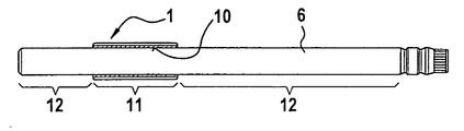
- FIG. 1 illustrates an outer joining part 1 of a component having an overload safeguard on a joining connection, the said outer joining part having a through-opening 2 and radial webs 3 which run along the longitudinal extent of the joining part 1 and are arranged offset with respect to one another in the circumferential direction (FIG. 2).
- the outer joining part 1 forms a clamping ring which interacts with the locking element of a steering wheel lock, the overload safeguard being integrated into a device securing against the unauthorized use of vehicles.
- the clamping ring is designed in a simple manner as a sleeve-shaped extruded profile which, as a mass-produced part, is cut to size from an endless profile.
- the use of the extruded profile does not require any complicated finishing work.
- the clamping ring has engagement grooves 5 which run axially between the webs 3 and in which the locking element of the steering wheel lock can engage in a retaining manner.
- the outer joining part 1 may also be impact-extruded or formed by internal high pressure from a rectilinear, cylindrical starting form into a final form configured with an engagement groove 5 . The latter method is favourable if the precise outer contour is important, for example if the locking element of the steering wheel lock engages in the engagement grooves 5 with the guarantee that it will not jam.
- the component which forms a steering column here, for example, furthermore has, in the joining connection, a cylindrical, inner joining part 6 (FIG. 3) which constitutes a steering spindle of the steering column.
- the joining part 6 is hollow and therefore of low weight in comparison with solid designs yet with high stiffness simultaneously being ensured.
- a plurality of recesses 8 and conical surfaces 9 are formed at one end 7 of the inner joining part 6 for connecting the steering spindle to the steering gear (FIG. 4).
- the steering spindle i.e.
- the hollow, inner joining part 6 can itself be a part formed by internal high pressure, in which case a rectilinear, cylindrical tube is placed into a forging die and is expanded under high fluidic internal pressure into its preliminary end form according to FIGS. 3 and 4 in accordance with the engraved shape of the forging die.
- the inner joining part 6 is fed into the through-opening 2 in the outer joining part 1 , so that the inner joining part 6 protrudes through the outer joining part 1 .
- the two joining parts 1 and 6 are then pressed together in this sliding position.
- the pressing can take place by shrinking the outer joining part 1 onto the inner joining part 6 or else, in an advantageous manner, can take place without the influence of thermal energy, by expansion of the inner joining part 6 , in which case that section 11 of the inner, hollow joining part 6 which is placed at the location of the press fit to be formed is plastically expanded relative to the diameter of the through-opening 2 in the outer joining part 1 , which diameter remains approximately the same, and is pressed onto the inner side 10 of the outer joining part 1 , which springs back elastically after the expansion.
- the joining part 6 therefore bears, with its outer circumference, against the inner circumference of the through-opening 2 in the outer joining part 1 .
- the expansion can be brought about by broaching or opening out the corresponding location of the inner joining part 6 .
- a rapid and reliable expansion method which also just as exactly reproduces the frictional connection, is the method involving partial formation by internal high pressure.
- an expansion lance is slid into the cavity of the inner joining part 6 , the expansion lance having an axial duct for guiding a fluidic medium which is under high pressure, the said axial duct having a radial hole which is positioned at the location of the expansion to be produced.
- the radial hole is sealed in both axial directions in a manner resistant to high pressure (>approximately 500 bar) by means of two radial seals arranged on the circumference of the expansion lance on both sides of the hole outlet.
- the internal high pressure only acts on that point of the inner joining part 6 which lies between the two radial seals.
- the press-on pressure, and therefore the strength of the frictional connection can be set in an extremely precise manner, depending on requirements and, of course, within the scope of the ductile yield of the inner joining part 6 and of the elasticity of deformation of the outer joining part 1 .
- the inner joining part 6 therefore expands plastically until it extensively and fixedly bears against the inner side 10 of the outer joining part 1 .
- the outer joining part 1 also expands temporarily, but only in the elastic range, so that after the pressure is relieved, the material of the outer joining part 1 springs elastically towards the plastically expanded, inner joining part 6 , as a result of which there is a high frictional connection between joining parts 1 and 6 .
- the local design of the frictional connection can be based on a plurality of alternatives.
- the frictional connection can be formed locally just in a pointwise manner, for which purpose the inner joining part 6 is pressed peripherally onto the outer joining part 1 at at least one axial position within the extent of the outer joining part 1 , which makes the production particularly rapid, in particular in the case of an expansion method—used on the inner joining part 6 .
- the inner joining part 6 can be expanded along the entire axial region of extent of the through-opening 2 in the outer joining part 1 . In this case, the support of the outer joining part 1 on the joining part 6 , i.e.
- the joining connection overall, is advantageous with regard to its fatigue strength, since torques acting on the joining connection are broadly distributed over the extent of the outer joining part 1 .
- the sections 12 lying outside the outer joining part 1 can be expanded. This results in the outer joining part 1 being embedded into the inner joining part 6 in a form-fitting manner in the axial direction, and therefore in a particularly good, non-slip, axial support.
- the overload safeguard on the joining connection described acts as follows, taking the example of the steering spindle.
- the joining part 6 the steering spindle, which is acted upon by torque, is frictionally connected to the clamping ring, the outer joining part 1 , by pressing them directly together. If now in the closed state of the steering wheel lock, in which a locking element engages in an engagement groove 5 of the clamping ring, the steering wheel—and, connected therewith, the steering spindle—is rotated, then the torque of the steering spindle is counteracted by a torque of equal magnitude to it via the locking resistance of the locking element engaging in the clamping ring.
- the frictional connection between the steering spindle and clamping ring is set in such a manner that when a torque value corresponding to the maximum permissible frictional force is exceeded, the frictional connection is released and the steering spindle slips in the connection.
- the matching, maximum torque value can advantageously be set very exactly and, similarly, in a simple manner—with just one mould and merely by regulating the pressure—can be widely varied to suit diverse application purposes.
- the steering spindle therefore bears against the clamping ring with a prestressing force corresponding to the predetermined torque value.
- the torque value determined here for steering-spindle applications lies in the range of between 120 and 190 Nm. Below 120 Nm, the steering spindle would be impermissibly too easy to move and above 190 Nm, the steering spindle would, as mentioned, be damaged.
Landscapes
- Engineering & Computer Science (AREA)
- Mechanical Engineering (AREA)
- General Engineering & Computer Science (AREA)
- Steering Controls (AREA)
- Pressure Welding/Diffusion-Bonding (AREA)
- Measurement Of The Respiration, Hearing Ability, Form, And Blood Characteristics Of Living Organisms (AREA)
- Orthopedics, Nursing, And Contraception (AREA)
- Dowels (AREA)
- Mutual Connection Of Rods And Tubes (AREA)
Applications Claiming Priority (3)
| Application Number | Priority Date | Filing Date | Title |
|---|---|---|---|
| DE10031902.5 | 2000-06-30 | ||
| DE10031902A DE10031902B4 (de) | 2000-06-30 | 2000-06-30 | Überlastsicherung und ein Verfahren zu deren Herstellung |
| PCT/EP2001/007155 WO2002002377A1 (de) | 2000-06-30 | 2001-06-23 | Überlastsicherung und ein verfahren zu deren herstellung |
Publications (1)
| Publication Number | Publication Date |
|---|---|
| US20040020249A1 true US20040020249A1 (en) | 2004-02-05 |
Family
ID=7647356
Family Applications (1)
| Application Number | Title | Priority Date | Filing Date |
|---|---|---|---|
| US10/312,636 Abandoned US20040020249A1 (en) | 2000-06-30 | 2001-06-23 | Overload safety device and method for the production thereof |
Country Status (7)
| Country | Link |
|---|---|
| US (1) | US20040020249A1 (de) |
| EP (1) | EP1294594B1 (de) |
| JP (1) | JP3760152B2 (de) |
| AT (1) | ATE280693T1 (de) |
| DE (2) | DE10031902B4 (de) |
| ES (1) | ES2230339T3 (de) |
| WO (1) | WO2002002377A1 (de) |
Cited By (8)
| Publication number | Priority date | Publication date | Assignee | Title |
|---|---|---|---|---|
| US20050092044A1 (en) * | 2003-11-05 | 2005-05-05 | Michel Chartrain | Anti-theft locking means for a vehicle steering shaft |
| US7562548B1 (en) * | 2008-06-16 | 2009-07-21 | Delphi Technologies, Inc. | Steering column assembly |
| US20090229325A1 (en) * | 2008-03-11 | 2009-09-17 | Delphi Technologies, Inc. | Column lock assembly |
| US8910365B2 (en) | 2009-08-21 | 2014-12-16 | Thyssenkrupp Presta Aktiengesellschaft | Method for the production of a steering spindle portion forming a section of a steering spindle |
| EP3332954A1 (de) * | 2016-11-25 | 2018-06-13 | Aida Engineering, Ltd. | Gleitreibungskrafterzeugungsmechanismus und ziehkissen für pressmaschine |
| US20180244236A1 (en) * | 2015-08-31 | 2018-08-30 | Thyssenkrupp Presta Ag | Detent star wheel for a steering column of a motor vehicle and method for producing the same |
| CN110242682A (zh) * | 2019-04-22 | 2019-09-17 | 武汉理工大学 | 一种基于碳纤维复合材料的传动轴扭矩过载保护方法 |
| US10532761B2 (en) * | 2017-12-06 | 2020-01-14 | Thyssenkrupp Presta Ag | Spindle and steering column assembly having same |
Families Citing this family (3)
| Publication number | Priority date | Publication date | Assignee | Title |
|---|---|---|---|---|
| ATE449710T1 (de) | 2004-02-26 | 2009-12-15 | Thyssenkrupp Presta Ag | Blockierhülse für eine lenksäule und verfahren zur herstellung derselben |
| JP4817007B2 (ja) * | 2005-12-02 | 2011-11-16 | 日本精工株式会社 | ステアリング装置 |
| DE102010047998A1 (de) * | 2010-10-08 | 2012-04-12 | Volkswagen Ag | Fahrzeuglenkung mit einer Lenkungsverriegelung |
Citations (11)
| Publication number | Priority date | Publication date | Assignee | Title |
|---|---|---|---|---|
| US2472925A (en) * | 1944-09-07 | 1949-06-14 | Lipe Rollway Corp | Overload or fixed load clutch |
| US3257502A (en) * | 1963-12-09 | 1966-06-21 | Ohio Brass Co | Compression joint for bushing insulator |
| US3321565A (en) * | 1964-01-03 | 1967-05-23 | Eastman Kodak Co | Method of manufacturing a friction clutch |
| US4635333A (en) * | 1980-06-05 | 1987-01-13 | The Babcock & Wilcox Company | Tube expanding method |
| US4771618A (en) * | 1985-10-09 | 1988-09-20 | Neiman S. A. | Motor-vehicle steering-wheel lock |
| US4854141A (en) * | 1985-05-31 | 1989-08-08 | Nacam | Anti-rotation locking device including a torque limitation for a motor vehicle steering column |
| US4993282A (en) * | 1988-02-07 | 1991-02-19 | Emitec Gesellschaft Fur Emissionstechnologie Mbh | Assembled shaft, especially camshaft, crankshaft or driveshaft |
| US5253947A (en) * | 1990-10-23 | 1993-10-19 | Gkn Automotive Ag | Connection between a tubular shaft made of a fiber composite material and a metal journal, as well as a method of producing such a connection |
| US5937500A (en) * | 1995-03-02 | 1999-08-17 | The Torrington Company | Method for making a steering column assembly |
| US20040118239A1 (en) * | 2000-11-09 | 2004-06-24 | Holger Kittler | Casing tube of a steering column of a motor vehicle and a method for producing the casing tube |
| US6810763B1 (en) * | 1999-02-15 | 2004-11-02 | Valeo Gmbh & Co. Scherheitssysteme | Arrangement for electrically locking the steering shaft of a steering device |
Family Cites Families (12)
| Publication number | Priority date | Publication date | Assignee | Title |
|---|---|---|---|---|
| DE2709633C3 (de) * | 1976-03-26 | 1981-04-23 | Combustion Engineering, Inc., 06095 Windsor, Conn. | Vorrichtung zum Befestigen einer Muffe in einer Rohrleitung |
| DE3435084A1 (de) * | 1984-09-25 | 1986-04-03 | Daimler-Benz Ag, 7000 Stuttgart | Lenkschloss fuer kraftfahrzeuge |
| DE3629639A1 (de) * | 1986-08-30 | 1988-03-10 | Lemfoerder Metallwaren Ag | Vorrichtung zur sicherung von kraftfahrzeugen gegen unbefugte benutzung |
| CA1326128C (en) * | 1987-09-24 | 1994-01-18 | Robert H. Johnson | Method of apparatus for expanding and sealing a sleeve into a surrounding tube |
| DE4107222C2 (de) * | 1990-10-23 | 1994-12-15 | Gkn Automotive Ag | Verbindung zwischen einer rohrförmigen Welle aus einem Faserverbundwerkstoff und einem Metallzapfen, sowie Verfahren zu ihrer Herstellung |
| DE4112366C1 (de) * | 1991-04-16 | 1992-07-16 | Balcke-Duerr Ag, 4030 Ratingen, De | |
| FR2690662B1 (fr) * | 1992-05-04 | 1997-06-13 | Ecia Equip Composants Ind Auto | Ensemble de colonne de direction a antivol, notamment pour vehicule automobile. |
| DE4221962C2 (de) * | 1992-06-30 | 1994-11-17 | Emitec Emissionstechnologie | Vorrichtung zum gleichzeitigen Befestigen mehrerer Bauteile an axial beabstandeten Befestigungsstellen eines Hohlkörpers |
| DE4413514C1 (de) * | 1994-04-19 | 1995-04-06 | Friedrich Weber | Überlastsicherung für Schlösser |
| FR2724469B1 (fr) * | 1994-09-14 | 1996-12-13 | Ecia Equip Composants Ind Auto | Dispositif de blocage en rotation a limitation de couple, notamment pour colonne de direction de vehicule automobile |
| JP3453909B2 (ja) * | 1995-03-17 | 2003-10-06 | 日本精工株式会社 | ステアリングロック装置 |
| DE19703533C2 (de) * | 1997-01-31 | 1998-12-03 | Zahnradfabrik Friedrichshafen | Antrieb mit einer drehfesten Verbindung einer Welle mit einer Nabe |
-
2000
- 2000-06-30 DE DE10031902A patent/DE10031902B4/de not_active Expired - Fee Related
-
2001
- 2001-06-23 EP EP20010951630 patent/EP1294594B1/de not_active Expired - Lifetime
- 2001-06-23 JP JP2002507650A patent/JP3760152B2/ja not_active Expired - Fee Related
- 2001-06-23 DE DE50104306T patent/DE50104306D1/de not_active Expired - Fee Related
- 2001-06-23 AT AT01951630T patent/ATE280693T1/de not_active IP Right Cessation
- 2001-06-23 ES ES01951630T patent/ES2230339T3/es not_active Expired - Lifetime
- 2001-06-23 US US10/312,636 patent/US20040020249A1/en not_active Abandoned
- 2001-06-23 WO PCT/EP2001/007155 patent/WO2002002377A1/de not_active Ceased
Patent Citations (11)
| Publication number | Priority date | Publication date | Assignee | Title |
|---|---|---|---|---|
| US2472925A (en) * | 1944-09-07 | 1949-06-14 | Lipe Rollway Corp | Overload or fixed load clutch |
| US3257502A (en) * | 1963-12-09 | 1966-06-21 | Ohio Brass Co | Compression joint for bushing insulator |
| US3321565A (en) * | 1964-01-03 | 1967-05-23 | Eastman Kodak Co | Method of manufacturing a friction clutch |
| US4635333A (en) * | 1980-06-05 | 1987-01-13 | The Babcock & Wilcox Company | Tube expanding method |
| US4854141A (en) * | 1985-05-31 | 1989-08-08 | Nacam | Anti-rotation locking device including a torque limitation for a motor vehicle steering column |
| US4771618A (en) * | 1985-10-09 | 1988-09-20 | Neiman S. A. | Motor-vehicle steering-wheel lock |
| US4993282A (en) * | 1988-02-07 | 1991-02-19 | Emitec Gesellschaft Fur Emissionstechnologie Mbh | Assembled shaft, especially camshaft, crankshaft or driveshaft |
| US5253947A (en) * | 1990-10-23 | 1993-10-19 | Gkn Automotive Ag | Connection between a tubular shaft made of a fiber composite material and a metal journal, as well as a method of producing such a connection |
| US5937500A (en) * | 1995-03-02 | 1999-08-17 | The Torrington Company | Method for making a steering column assembly |
| US6810763B1 (en) * | 1999-02-15 | 2004-11-02 | Valeo Gmbh & Co. Scherheitssysteme | Arrangement for electrically locking the steering shaft of a steering device |
| US20040118239A1 (en) * | 2000-11-09 | 2004-06-24 | Holger Kittler | Casing tube of a steering column of a motor vehicle and a method for producing the casing tube |
Cited By (13)
| Publication number | Priority date | Publication date | Assignee | Title |
|---|---|---|---|---|
| US7107801B2 (en) * | 2003-11-05 | 2006-09-19 | Nacam France S.A. | Anti-theft locking means for a vehicle steering shaft |
| US20050092044A1 (en) * | 2003-11-05 | 2005-05-05 | Michel Chartrain | Anti-theft locking means for a vehicle steering shaft |
| US20090229325A1 (en) * | 2008-03-11 | 2009-09-17 | Delphi Technologies, Inc. | Column lock assembly |
| US7681423B2 (en) * | 2008-03-11 | 2010-03-23 | Gm Global Technology Operations, Inc. | Column lock assembly |
| US7562548B1 (en) * | 2008-06-16 | 2009-07-21 | Delphi Technologies, Inc. | Steering column assembly |
| US8910365B2 (en) | 2009-08-21 | 2014-12-16 | Thyssenkrupp Presta Aktiengesellschaft | Method for the production of a steering spindle portion forming a section of a steering spindle |
| US10589714B2 (en) * | 2015-08-31 | 2020-03-17 | Thyssenkrupp Presta Ag | Detent star wheel for a steering column of a motor vehicle and method for producing the same |
| US20180244236A1 (en) * | 2015-08-31 | 2018-08-30 | Thyssenkrupp Presta Ag | Detent star wheel for a steering column of a motor vehicle and method for producing the same |
| EP3332954A1 (de) * | 2016-11-25 | 2018-06-13 | Aida Engineering, Ltd. | Gleitreibungskrafterzeugungsmechanismus und ziehkissen für pressmaschine |
| US10974303B2 (en) | 2016-11-25 | 2021-04-13 | Aida Engineering, Ltd. | Sliding frictional force generation mechanism by fitting and die cushion for press machine |
| US10532761B2 (en) * | 2017-12-06 | 2020-01-14 | Thyssenkrupp Presta Ag | Spindle and steering column assembly having same |
| US11091187B2 (en) * | 2017-12-06 | 2021-08-17 | Thyssenkrupp Presta Ag | Spindle and steering column assembly having same |
| CN110242682A (zh) * | 2019-04-22 | 2019-09-17 | 武汉理工大学 | 一种基于碳纤维复合材料的传动轴扭矩过载保护方法 |
Also Published As
| Publication number | Publication date |
|---|---|
| DE10031902B4 (de) | 2005-06-16 |
| JP3760152B2 (ja) | 2006-03-29 |
| ATE280693T1 (de) | 2004-11-15 |
| WO2002002377B1 (de) | 2002-03-21 |
| ES2230339T3 (es) | 2005-05-01 |
| WO2002002377A1 (de) | 2002-01-10 |
| DE50104306D1 (de) | 2004-12-02 |
| EP1294594B1 (de) | 2004-10-27 |
| EP1294594A1 (de) | 2003-03-26 |
| JP2004502586A (ja) | 2004-01-29 |
| DE10031902A1 (de) | 2002-02-07 |
Similar Documents
| Publication | Publication Date | Title |
|---|---|---|
| US5718131A (en) | Steering column locking assembly | |
| KR0155028B1 (ko) | 충격 흡수식 스티어링 샤프트의 제조 방법 | |
| US7413222B2 (en) | Position adjustment type steering column device for vehicles | |
| US4572022A (en) | Steering column for a motor vehicle steering mechanism and method of producing the column | |
| US20040020249A1 (en) | Overload safety device and method for the production thereof | |
| US8882146B2 (en) | Column unit for an electric power steering apparatus | |
| US8910365B2 (en) | Method for the production of a steering spindle portion forming a section of a steering spindle | |
| US7186030B2 (en) | Expandable shaft assembly | |
| EP2885547B1 (de) | Blindnietanordnung | |
| US5782566A (en) | Method of assembling a vehicle wheel hub bearing to a respective upright, and bearing-upright unit so formed | |
| US20060188328A1 (en) | Shaft/hub connection with securing system | |
| EP1156229A1 (de) | Verbindungsstruktur einer teleskopstange | |
| WO2011112203A1 (en) | Rotatable bar pin bushing assembly | |
| WO2007066634A1 (ja) | 車輪支持用転がり軸受ユニットを構成する軌道輪部材の製造方法 | |
| US7076854B2 (en) | Method for the production of a shaft-hub connection | |
| US9487229B2 (en) | Steering column for a motor vehicle | |
| EP0810140B1 (de) | Welle für die Drehmomentübertragung in einer Lenkeinheit und Verfahren für ihren Zusammenbau | |
| WO2020085411A1 (ja) | ステアリングコラム装置 | |
| US6935657B2 (en) | Steering shaft for energy absorbing steering column and manufacturing method thereof | |
| US9610971B2 (en) | Column unit for an electric power steering apparatus | |
| US7296947B2 (en) | Arrangement having a first component, a second component and a connecting element | |
| US6068296A (en) | Shock absorbing type steering column assembly | |
| US6925714B2 (en) | Upper steering shaft-assembly | |
| US7370553B2 (en) | Steering spindle arrangement and a method for the production thereof | |
| JP2022085813A (ja) | 中間シャフト |
Legal Events
| Date | Code | Title | Description |
|---|---|---|---|
| AS | Assignment |
Owner name: DAIMLERCHRYSLER AG, GERMANY Free format text: ASSIGNMENT OF ASSIGNORS INTEREST;ASSIGNORS:BATTERMANN, JENS;GAERTNER, STEPHAN;HARMS, TORSTEN;AND OTHERS;REEL/FRAME:014471/0390;SIGNING DATES FROM 20030107 TO 20030115 |
|
| STCB | Information on status: application discontinuation |
Free format text: ABANDONED -- FAILURE TO RESPOND TO AN OFFICE ACTION |