US20030196652A1 - Solar energy collector system - Google Patents
Solar energy collector system Download PDFInfo
- Publication number
- US20030196652A1 US20030196652A1 US10/128,734 US12873402A US2003196652A1 US 20030196652 A1 US20030196652 A1 US 20030196652A1 US 12873402 A US12873402 A US 12873402A US 2003196652 A1 US2003196652 A1 US 2003196652A1
- Authority
- US
- United States
- Prior art keywords
- solar energy
- collector system
- energy collector
- heating unit
- housing structure
- Prior art date
- Legal status (The legal status is an assumption and is not a legal conclusion. Google has not performed a legal analysis and makes no representation as to the accuracy of the status listed.)
- Granted
Links
- 239000012530 fluid Substances 0.000 claims abstract description 46
- 238000010438 heat treatment Methods 0.000 claims abstract description 36
- 230000004888 barrier function Effects 0.000 claims description 17
- 239000000463 material Substances 0.000 claims description 7
- RYGMFSIKBFXOCR-UHFFFAOYSA-N Copper Chemical compound [Cu] RYGMFSIKBFXOCR-UHFFFAOYSA-N 0.000 claims description 3
- 239000010949 copper Substances 0.000 claims description 3
- 229910052802 copper Inorganic materials 0.000 claims description 3
- 230000005611 electricity Effects 0.000 abstract description 9
- 238000004378 air conditioning Methods 0.000 abstract description 8
- 230000000630 rising effect Effects 0.000 abstract description 3
- 238000010276 construction Methods 0.000 description 5
- 239000007789 gas Substances 0.000 description 3
- XLYOFNOQVPJJNP-UHFFFAOYSA-N water Substances O XLYOFNOQVPJJNP-UHFFFAOYSA-N 0.000 description 3
- 238000004519 manufacturing process Methods 0.000 description 2
- 238000012986 modification Methods 0.000 description 2
- 230000004048 modification Effects 0.000 description 2
- 239000003570 air Substances 0.000 description 1
- XAGFODPZIPBFFR-UHFFFAOYSA-N aluminium Chemical compound [Al] XAGFODPZIPBFFR-UHFFFAOYSA-N 0.000 description 1
- 229910052782 aluminium Inorganic materials 0.000 description 1
- 230000003466 anti-cipated effect Effects 0.000 description 1
- 239000004566 building material Substances 0.000 description 1
- 238000000576 coating method Methods 0.000 description 1
- 238000001816 cooling Methods 0.000 description 1
- 238000011161 development Methods 0.000 description 1
- 239000011810 insulating material Substances 0.000 description 1
- 238000000034 method Methods 0.000 description 1
- 238000011160 research Methods 0.000 description 1
- 125000006850 spacer group Chemical group 0.000 description 1
- 239000000126 substance Substances 0.000 description 1
- 239000012780 transparent material Substances 0.000 description 1
Images


Classifications
-
- F—MECHANICAL ENGINEERING; LIGHTING; HEATING; WEAPONS; BLASTING
- F24—HEATING; RANGES; VENTILATING
- F24S—SOLAR HEAT COLLECTORS; SOLAR HEAT SYSTEMS
- F24S10/00—Solar heat collectors using working fluids
- F24S10/50—Solar heat collectors using working fluids the working fluids being conveyed between plates
-
- H—ELECTRICITY
- H10—SEMICONDUCTOR DEVICES; ELECTRIC SOLID-STATE DEVICES NOT OTHERWISE PROVIDED FOR
- H10N—ELECTRIC SOLID-STATE DEVICES NOT OTHERWISE PROVIDED FOR
- H10N10/00—Thermoelectric devices comprising a junction of dissimilar materials, i.e. devices exhibiting Seebeck or Peltier effects
- H10N10/10—Thermoelectric devices comprising a junction of dissimilar materials, i.e. devices exhibiting Seebeck or Peltier effects operating with only the Peltier or Seebeck effects
- H10N10/13—Thermoelectric devices comprising a junction of dissimilar materials, i.e. devices exhibiting Seebeck or Peltier effects operating with only the Peltier or Seebeck effects characterised by the heat-exchanging means at the junction
-
- Y—GENERAL TAGGING OF NEW TECHNOLOGICAL DEVELOPMENTS; GENERAL TAGGING OF CROSS-SECTIONAL TECHNOLOGIES SPANNING OVER SEVERAL SECTIONS OF THE IPC; TECHNICAL SUBJECTS COVERED BY FORMER USPC CROSS-REFERENCE ART COLLECTIONS [XRACs] AND DIGESTS
- Y02—TECHNOLOGIES OR APPLICATIONS FOR MITIGATION OR ADAPTATION AGAINST CLIMATE CHANGE
- Y02B—CLIMATE CHANGE MITIGATION TECHNOLOGIES RELATED TO BUILDINGS, e.g. HOUSING, HOUSE APPLIANCES OR RELATED END-USER APPLICATIONS
- Y02B10/00—Integration of renewable energy sources in buildings
- Y02B10/20—Solar thermal
-
- Y—GENERAL TAGGING OF NEW TECHNOLOGICAL DEVELOPMENTS; GENERAL TAGGING OF CROSS-SECTIONAL TECHNOLOGIES SPANNING OVER SEVERAL SECTIONS OF THE IPC; TECHNICAL SUBJECTS COVERED BY FORMER USPC CROSS-REFERENCE ART COLLECTIONS [XRACs] AND DIGESTS
- Y02—TECHNOLOGIES OR APPLICATIONS FOR MITIGATION OR ADAPTATION AGAINST CLIMATE CHANGE
- Y02E—REDUCTION OF GREENHOUSE GAS [GHG] EMISSIONS, RELATED TO ENERGY GENERATION, TRANSMISSION OR DISTRIBUTION
- Y02E10/00—Energy generation through renewable energy sources
- Y02E10/40—Solar thermal energy, e.g. solar towers
- Y02E10/44—Heat exchange systems
Definitions
- the present invention relates generally to solar collecting devices and more specifically it relates to a solar energy collector system for reducing heating, air conditioning and power consumption of a building structure.
- Solar collecting devices have been in use for years. Conventional solar collecting devices can be grouped into two categories: heat collectors and electricity generators. Heat collectors typically are comprised of a tank of fluid positioned upon the roof of a building structure that is heated for use within the building structure as heated water. Electricity generators (solar cells) convert sunlight to electricity that may be stored within batteries and utilized within the building structure.
- Examples of patented devices which are related to the present invention include U.S. Pat. No. 4,301,789 to Artweger; U.S. Pat. No. 4,082,082 to Harvey; U.S. Pat. No. 4,334,524 to McCullough et al; U.S. Pat. No. 4,364,375 to Younghouse; U.S. Pat. No. 4,425,903 to Greiner; U.S. Pat. No. 4,823,772 to Lenz; U.S. Pat. No. 4,949,704 to Pflunger; U.S. Pat. No. 5,931,157 to Aschauer; U.S. Pat. No. 4,299,205 to Garfield; and U.S. Pat. No. 4,129,177 to Adcock.
- the solar energy collector system substantially departs from the conventional concepts and designs of the prior art, and in so doing provides an apparatus primarily developed for the purpose of reducing heating, air conditioning and power consumption of a building structure.
- the present invention provides a new solar energy collector system construction wherein the same can be utilized for reducing heating, air conditioning and power consumption of a building structure.
- the general purpose of the present invention is to provide a new solar energy collector system that has many of the advantages of the solar collectors mentioned heretofore and many novel features that result in a new solar energy collector system which is not anticipated, rendered obvious, suggested, or even implied by any of the prior art solar collectors, either alone or in any combination thereof.
- the present invention generally comprises a housing structure, a collector plate, an insulating sheet positioned between the collector plate and a floor of the housing structure, a thermopile unit within the housing structure, and a fluid positioned below the collector plate.
- the fluid adjacent the collector plate is heated thereby rising to an upper portion of the housing structure and thermally conducting the thermopile unit for generating electricity.
- the cooled fluid then passes downwardly below the insulating sheet to a lower portion of the housing structure.
- a heat exchanger is utilized upon the opposite side of the thermopile unit for transferring the heat to a desired location within or outside of the building structure.
- a primary object of the present invention is to provide a solar energy collector system that will overcome the shortcomings of the prior art devices.
- a second object is to provide a solar energy collector system for reducing heating, air conditioning and power consumption of a building structure.
- Another object is to provide a solar energy collector system that provides an inexpensive system for moderating a building environment.
- An additional object is to provide a solar energy collector system that may be utilized upon large portions of a roof and that may be utilized for large portions of a roof.
- a further object is to provide a solar energy collector system that produces electricity from heat rather than sunlight.
- Another object is to provide a solar energy collector system that increases the overall efficiency in utilizing solar energy.
- a further object is to provide a solar energy collector system that is cheaper to manufacture than conventional photovoltaic power cells.
- Another object is to provide a solar energy collector system that reduces the air conditioning requirements of a building structure.
- a further object is to provide a solar energy collector system that may be utilized as a source for hot water, heat and electrical power.
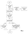
- FIG. 1 is a flowchart of the operation of the present invention.
- FIG. 2 is an upper perspective view of the present invention.
- FIG. 3 is an exploded upper perspective view of the present invention.
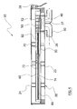
- FIG. 4 is a cross sectional view taken along line 4 - 4 of FIG. 2.
- FIG. 5 is an upper perspective view of the collector plate surrounding the first plate and the insulating sheets between thereof.
- FIG. 6 is an upper perspective view of the insulating sheet positioned upon the first plate with the conducting member attached upon.
- FIGS. 1 through 6 illustrate a solar energy collector system 10 , which comprises a housing structure 20 , a collector plate 60 , an insulating sheet positioned between the collector plate 60 and a floor of the housing structure 20 , a thermopile unit 40 within the housing structure 20 , and a fluid positioned below the collector plate 60 .
- the fluid adjacent the collector plate 60 is heated thereby rising to an upper portion of the housing structure 20 and thermally conducting the thermopile unit 40 for generating electricity.
- the cooled fluid then passes downwardly below the insulating sheet to a lower portion of the housing structure 20 .
- a heat exchanger 90 is utilized upon the opposite side of the thermopile unit 40 for transferring the heat to a desired location within or outside of the building structure.
- FIG. 2 illustrates an upper perspective of the present invention having a generally flat structure.
- the present invention designed to be utilized upon a pre-existing roof surface or as a roof surface.
- Various other configurations may be utilized in conjunction with the present invention.
- the housing structure 20 includes an interior portion 22 that receives the main components of the present invention.
- the housing structure 20 may have various shapes and sizes that may be required for usage upon a roof of the building structure.
- the housing structure 20 may also be constructed of various types of building materials.
- a housing opening 27 extends through an upper portion of the housing structure 20 for connecting to a heat exchanger 90 (heat sink).
- the housing opening 27 may have various sizes and shapes suitable for connecting to the heat exchanger 90 .
- the heat exchanger 90 utilizes air, gas or fluid to exchange heat transferred from the thermopile unit 40 wherein the conducted heat may be dispersed to the appropriate locations within the building structure for heating or outside of the building structure to reducing air conditioning requirements of the building structure.
- a plurality of support posts 23 extend from the interior floor of the housing structure 20 to support a first plate 30 .
- the first plate 30 is secured within the housing structure 20 in a sealed manner to prevent the fluid from passing through.
- a first support 26 surrounding the housing opening 27 is attached to the bottom surface of the first plate 30 about a corresponding first opening 32 within the first plate 30 .
- the first opening 32 is covered with a conducting member 50 that is comprised of a material capable of efficient thermal conduction such as a copper plate or similar material.
- the thermopile unit 40 is attached to the lower surface of the conducting member 50 as shown in FIG. 4 of the drawings.
- a plurality of spacers 52 extend upwardly from the conducting member 50 to engage and support a portion of the collector plate 60 as best shown in FIG. 4 of the drawings.
- first support members 80 are attached to the upper surface of the first plate 30 .
- the inner first support members 80 are preferably shorter in length to allow for fluid flow near the conducting member 50 as shown in FIG. 3 of the drawings.
- a first insulating sheet 70 and a second insulating sheet 74 are attached about a middle support sheet 72 defining an insulating barrier to separate the heated and cooled fluid in an insulated manner.
- the first insulating sheet 70 and the second insulating sheet 74 may be comprised of any well-known insulating material capable of withstanding relatively high temperatures.
- the middle support sheet 72 is comprised of a rigid material such as but not limited to aluminum for providing support to the insulating barrier.
- the insulating barrier is attached to the first support members 80 opposite of the first plate 30 thereby defining a lower fluid channel for allowing cooled fluid from the conducting member 50 to return to a lower portion of the upper fluid channel to be heated as illustrated in FIGS. 3 and 4 of the drawings.
- the insulating barrier also has a cutout at the end adjacent the conducting member 50 for facilitating the flow of heated fluid about the conducting member 50 and between the lower and upper fluid channels.
- a plurality of second support members 82 are attached to the upper surface of the first insulating sheet 70 .
- the inner second support members 82 are preferably shorter in length to allow for fluid flow near the conducting member 50 as shown in FIG. 3 of the drawings.
- a collector plate 60 is attached in a sealed manner to the first plate 30 and adjacent the second support members 82 .
- An upper fluid channel is defined between the first insulating sheet 70 and the collector plate 60 for allowing the heated fluid to pass upwardly to the conducting member 50 as shown in FIG. 4 of the drawings.
- the collector plate 60 is comprised of a material capable of absorbing solar heat and efficiently transferring the conducted solar heat to the fluid within the upper fluid channel.
- the collector plate 60 may be coated with various solar energy absorbing coatings.
- the cavity defined between the collector plate 60 and the first plate 30 is a sealed heating unit for heating the fluid within and transferring this heat to the conducting member 50 .
- the fluid positioned within the heating unit is comprised of a fluid capable of efficiently receiving and transferring heat from the collector plate 60 to the conducting member 50 .
- the fluid is preferably comprised of an oil substance for reducing the production of gases during heating/cooling, however, various other fluids may be utilized within the heating unit.
- a cover 24 is preferably attached about the housing structure 20 for enclosing the entire interior portion 22 as shown in FIGS. 3, 4 and 5 of the drawings.
- the cover 24 is comprised of a transparent material for allowing for the passage of solar energy to the collector plate 60 .
- the cover 24 may be coated for reducing the amount of solar energy reflected by the collector plate 60 thereby increasing the heating of the collector plate 60 .
- a pressure relief valve 28 may be utilized within the housing structure 20 between the cover 24 and the collector plate 60 for allowing for the release of gas within at a predetermined pressure to avoid damaging pressure from accumulating within but also reducing the exchange of heat from the housing structure 20 .
- the housing structure 20 is either attached to an existing roof or built within the building structure as part of the roof in the direction of the sun at an angle of at least 5 degrees.
- the solar energy heats the collector plate 60 .
- the fluid beneath the collector plate 60 within the upper fluid channel of the heating unit conducts this heat and then rises upwardly along the upper fluid channel toward the conducting member 50 as shown in FIG. 4 of the drawings.
- the heated fluid passes over the conducting member 50 which conducts the heat energy from the fluid and transfers the heat energy to the thermopile unit 40 thereby generating electricity as shown in FIG. 4 of the drawings.
- the heat exchanger 90 conducts the heat from the thermopile unit 40 thereby increasing the efficiency of the thermopile unit 40 and providing heat for the interior of the building structure if required. If heating within the building structure is not required nor desired, the heat exchanger 90 may direct the heat outside of the building structure thereby reducing solar heating of the building structure. The cooled fluid then passes downwardly along the lower fluid channel wherein it eventually returns to the upper fluid channel through a lower passage at the end of the insulating barrier to be heated again as shown in FIG. 4 of the drawings. This process continues repeated thereby providing a continuous electrical supply from the thermopile unit 40 and heat supply through the heat exchanger 90 . The heat exchanger 90 may also provide heated water for usage within the building structure if desired.
Landscapes
- Engineering & Computer Science (AREA)
- Physics & Mathematics (AREA)
- Life Sciences & Earth Sciences (AREA)
- Sustainable Development (AREA)
- Sustainable Energy (AREA)
- Thermal Sciences (AREA)
- Chemical & Material Sciences (AREA)
- Combustion & Propulsion (AREA)
- Mechanical Engineering (AREA)
- General Engineering & Computer Science (AREA)
- Roof Covering Using Slabs Or Stiff Sheets (AREA)
Abstract
A solar energy collector system for reducing heating, air conditioning and power consumption of a building structure. The solar energy collector system includes a housing structure, a collector plate, an insulating sheet positioned between the collector plate and a floor of the housing structure, a thermopile unit within the housing structure, and a fluid positioned below the collector plate. The fluid adjacent the collector plate is heated thereby rising to an upper portion of the housing structure and thermally conducting the thermopile unit for generating electricity. The cooled fluid then passes downwardly below the insulating sheet to a lower portion of the housing structure. A heat exchanger is utilized upon the opposite side of the thermopile unit for transferring the heat to a desired location within or outside of the building structure.
Description
- Not applicable to this application.
- Not applicable to this application.
- 1.Field of the Invention
- The present invention relates generally to solar collecting devices and more specifically it relates to a solar energy collector system for reducing heating, air conditioning and power consumption of a building structure.
- 2.Description of the Related Art
- Solar collecting devices have been in use for years. Conventional solar collecting devices can be grouped into two categories: heat collectors and electricity generators. Heat collectors typically are comprised of a tank of fluid positioned upon the roof of a building structure that is heated for use within the building structure as heated water. Electricity generators (solar cells) convert sunlight to electricity that may be stored within batteries and utilized within the building structure.
- The main problem with conventional solar collecting devices is that they are typically relatively expensive. Another problem with conventional solar collecting devices is that they do not efficiently convert solar energy to usable energy (heat or electricity) for a building structure. Another problem with conventional solar collecting devices is that they are designed as an additional structure for a building structure and not as part of the building structure to lower cost of construction.
- Examples of patented devices which are related to the present invention include U.S. Pat. No. 4,301,789 to Artweger; U.S. Pat. No. 4,082,082 to Harvey; U.S. Pat. No. 4,334,524 to McCullough et al; U.S. Pat. No. 4,364,375 to Younghouse; U.S. Pat. No. 4,425,903 to Greiner; U.S. Pat. No. 4,823,772 to Lenz; U.S. Pat. No. 4,949,704 to Pflunger; U.S. Pat. No. 5,931,157 to Aschauer; U.S. Pat. No. 4,299,205 to Garfield; and U.S. Pat. No. 4,129,177 to Adcock.
- While these devices may be suitable for the particular purpose to which they address, they are not as suitable for reducing heating, air conditioning and power consumption of a building structure. Conventional solar collecting devices do not efficiently utilize solar energy.
- In these respects, the solar energy collector system according to the present invention substantially departs from the conventional concepts and designs of the prior art, and in so doing provides an apparatus primarily developed for the purpose of reducing heating, air conditioning and power consumption of a building structure.
- In view of the foregoing disadvantages inherent in the known types of solar collectors now present in the prior art, the present invention provides a new solar energy collector system construction wherein the same can be utilized for reducing heating, air conditioning and power consumption of a building structure.
- The general purpose of the present invention, which will be described subsequently in greater detail, is to provide a new solar energy collector system that has many of the advantages of the solar collectors mentioned heretofore and many novel features that result in a new solar energy collector system which is not anticipated, rendered obvious, suggested, or even implied by any of the prior art solar collectors, either alone or in any combination thereof.
- To attain this, the present invention generally comprises a housing structure, a collector plate, an insulating sheet positioned between the collector plate and a floor of the housing structure, a thermopile unit within the housing structure, and a fluid positioned below the collector plate. The fluid adjacent the collector plate is heated thereby rising to an upper portion of the housing structure and thermally conducting the thermopile unit for generating electricity. The cooled fluid then passes downwardly below the insulating sheet to a lower portion of the housing structure. A heat exchanger is utilized upon the opposite side of the thermopile unit for transferring the heat to a desired location within or outside of the building structure.
- There has thus been outlined, rather broadly, the more important features of the invention in order that the detailed description thereof may be better understood, and in order that the present contribution to the art may be better appreciated. There are additional features of the invention that will be described hereinafter and that will form the subject matter of the claims appended hereto.
- In this respect, before explaining at least one embodiment of the invention in detail, it is to be understood that the invention is not limited in its application to the details of construction and to the arrangements of the components set forth in the following description or illustrated in the drawings. The invention is capable of other embodiments and of being practiced and carried out in various ways. Also, it is to be understood that the phraseology and terminology employed herein are for the purpose of the description and should not be regarded as limiting.
- A primary object of the present invention is to provide a solar energy collector system that will overcome the shortcomings of the prior art devices.
- A second object is to provide a solar energy collector system for reducing heating, air conditioning and power consumption of a building structure.
- Another object is to provide a solar energy collector system that provides an inexpensive system for moderating a building environment.
- An additional object is to provide a solar energy collector system that may be utilized upon large portions of a roof and that may be utilized for large portions of a roof.
- A further object is to provide a solar energy collector system that produces electricity from heat rather than sunlight.
- Another object is to provide a solar energy collector system that increases the overall efficiency in utilizing solar energy.
- A further object is to provide a solar energy collector system that is cheaper to manufacture than conventional photovoltaic power cells.
- Another object is to provide a solar energy collector system that reduces the air conditioning requirements of a building structure.
- A further object is to provide a solar energy collector system that may be utilized as a source for hot water, heat and electrical power.
- Other objects and advantages of the present invention will become obvious to the reader and it is intended that these objects and advantages are within the scope of the present invention.
- To the accomplishment of the above and related objects, this invention may be embodied in the form illustrated in the accompanying drawings, attention being called to the fact, however, that the drawings are illustrative only, and that changes may be made in the specific construction illustrated and described within the scope of the appended claims.
- Various other objects, features and attendant advantages of the present invention will become fully appreciated as the same becomes better understood when considered in conjunction with the accompanying drawings, in which like reference characters designate the same or similar parts throughout the several views, and wherein:
- FIG. 1 is a flowchart of the operation of the present invention.
- FIG. 2 is an upper perspective view of the present invention.
- FIG. 3 is an exploded upper perspective view of the present invention.
- FIG. 4 is a cross sectional view taken along line 4-4 of FIG. 2.
- FIG. 5 is an upper perspective view of the collector plate surrounding the first plate and the insulating sheets between thereof.
- FIG. 6 is an upper perspective view of the insulating sheet positioned upon the first plate with the conducting member attached upon.
- Turning now descriptively to the drawings, in which similar reference characters denote similar elements throughout the several views, FIGS. 1 through 6 illustrate a solar
energy collector system 10, which comprises ahousing structure 20, acollector plate 60, an insulating sheet positioned between thecollector plate 60 and a floor of thehousing structure 20, athermopile unit 40 within thehousing structure 20, and a fluid positioned below thecollector plate 60. The fluid adjacent thecollector plate 60 is heated thereby rising to an upper portion of thehousing structure 20 and thermally conducting thethermopile unit 40 for generating electricity. The cooled fluid then passes downwardly below the insulating sheet to a lower portion of thehousing structure 20. Aheat exchanger 90 is utilized upon the opposite side of thethermopile unit 40 for transferring the heat to a desired location within or outside of the building structure. - FIG. 2 illustrates an upper perspective of the present invention having a generally flat structure. The present invention designed to be utilized upon a pre-existing roof surface or as a roof surface. Various other configurations may be utilized in conjunction with the present invention.
- As shown in FIG. 3 of the drawings, the
housing structure 20 includes an interior portion 22 that receives the main components of the present invention. Thehousing structure 20 may have various shapes and sizes that may be required for usage upon a roof of the building structure. Thehousing structure 20 may also be constructed of various types of building materials. - A
housing opening 27 extends through an upper portion of thehousing structure 20 for connecting to a heat exchanger 90 (heat sink). Thehousing opening 27 may have various sizes and shapes suitable for connecting to theheat exchanger 90. Theheat exchanger 90 utilizes air, gas or fluid to exchange heat transferred from thethermopile unit 40 wherein the conducted heat may be dispersed to the appropriate locations within the building structure for heating or outside of the building structure to reducing air conditioning requirements of the building structure. - As shown in FIGS. 3 and 4 of the drawings, a plurality of support posts 23 extend from the interior floor of the
housing structure 20 to support afirst plate 30. Thefirst plate 30 is secured within thehousing structure 20 in a sealed manner to prevent the fluid from passing through. Afirst support 26 surrounding thehousing opening 27 is attached to the bottom surface of thefirst plate 30 about a corresponding first opening 32 within thefirst plate 30. The first opening 32 is covered with a conductingmember 50 that is comprised of a material capable of efficient thermal conduction such as a copper plate or similar material. Thethermopile unit 40 is attached to the lower surface of the conductingmember 50 as shown in FIG. 4 of the drawings. A plurality ofspacers 52 extend upwardly from the conductingmember 50 to engage and support a portion of thecollector plate 60 as best shown in FIG. 4 of the drawings. - As shown in FIGS. 3 and 4 of the drawings, a plurality of
first support members 80 are attached to the upper surface of thefirst plate 30. The innerfirst support members 80 are preferably shorter in length to allow for fluid flow near the conductingmember 50 as shown in FIG. 3 of the drawings. - A first insulating
sheet 70 and a second insulatingsheet 74 are attached about amiddle support sheet 72 defining an insulating barrier to separate the heated and cooled fluid in an insulated manner. The first insulatingsheet 70 and the second insulatingsheet 74 may be comprised of any well-known insulating material capable of withstanding relatively high temperatures. Themiddle support sheet 72 is comprised of a rigid material such as but not limited to aluminum for providing support to the insulating barrier. The insulating barrier is attached to thefirst support members 80 opposite of thefirst plate 30 thereby defining a lower fluid channel for allowing cooled fluid from the conductingmember 50 to return to a lower portion of the upper fluid channel to be heated as illustrated in FIGS. 3 and 4 of the drawings. The insulating barrier also has a cutout at the end adjacent the conductingmember 50 for facilitating the flow of heated fluid about the conductingmember 50 and between the lower and upper fluid channels. - As shown in FIGS. 3 and 6 of the drawings, a plurality of
second support members 82 are attached to the upper surface of the first insulatingsheet 70. The innersecond support members 82 are preferably shorter in length to allow for fluid flow near the conductingmember 50 as shown in FIG. 3 of the drawings. - As shown in FIGS. 3, 4 and 5 of the drawings, a
collector plate 60 is attached in a sealed manner to thefirst plate 30 and adjacent thesecond support members 82. An upper fluid channel is defined between the first insulatingsheet 70 and thecollector plate 60 for allowing the heated fluid to pass upwardly to the conductingmember 50 as shown in FIG. 4 of the drawings. - The
collector plate 60 is comprised of a material capable of absorbing solar heat and efficiently transferring the conducted solar heat to the fluid within the upper fluid channel. Thecollector plate 60 may be coated with various solar energy absorbing coatings. The cavity defined between thecollector plate 60 and thefirst plate 30 is a sealed heating unit for heating the fluid within and transferring this heat to the conductingmember 50. - The fluid positioned within the heating unit is comprised of a fluid capable of efficiently receiving and transferring heat from the
collector plate 60 to the conductingmember 50. The fluid is preferably comprised of an oil substance for reducing the production of gases during heating/cooling, however, various other fluids may be utilized within the heating unit. - A
cover 24 is preferably attached about thehousing structure 20 for enclosing the entire interior portion 22 as shown in FIGS. 3, 4 and 5 of the drawings. Thecover 24 is comprised of a transparent material for allowing for the passage of solar energy to thecollector plate 60. Thecover 24 may be coated for reducing the amount of solar energy reflected by thecollector plate 60 thereby increasing the heating of thecollector plate 60. Apressure relief valve 28 may be utilized within thehousing structure 20 between thecover 24 and thecollector plate 60 for allowing for the release of gas within at a predetermined pressure to avoid damaging pressure from accumulating within but also reducing the exchange of heat from thehousing structure 20. - In use, the
housing structure 20 is either attached to an existing roof or built within the building structure as part of the roof in the direction of the sun at an angle of at least 5 degrees. When the solar energy from the sun passes through thetransparent cover 24, the solar energy heats thecollector plate 60. The fluid beneath thecollector plate 60 within the upper fluid channel of the heating unit conducts this heat and then rises upwardly along the upper fluid channel toward the conductingmember 50 as shown in FIG. 4 of the drawings. The heated fluid passes over the conductingmember 50 which conducts the heat energy from the fluid and transfers the heat energy to thethermopile unit 40 thereby generating electricity as shown in FIG. 4 of the drawings. Theheat exchanger 90 conducts the heat from thethermopile unit 40 thereby increasing the efficiency of thethermopile unit 40 and providing heat for the interior of the building structure if required. If heating within the building structure is not required nor desired, theheat exchanger 90 may direct the heat outside of the building structure thereby reducing solar heating of the building structure. The cooled fluid then passes downwardly along the lower fluid channel wherein it eventually returns to the upper fluid channel through a lower passage at the end of the insulating barrier to be heated again as shown in FIG. 4 of the drawings. This process continues repeated thereby providing a continuous electrical supply from thethermopile unit 40 and heat supply through theheat exchanger 90. Theheat exchanger 90 may also provide heated water for usage within the building structure if desired. - As to a further discussion of the manner of usage and operation of the present invention, the same should be apparent from the above description. Accordingly, no further discussion relating to the manner of usage and operation will be provided.
- With respect to the above description then, it is to be realized that the optimum dimensional relationships for the parts of the invention, to include variations in size, materials, shape, form, function and manner of operation, assembly and use, are deemed to be within the expertise of those skilled in the art, and all equivalent structural variations and relationships to those illustrated in the drawings and described in the specification are intended to be encompassed by the present invention.
- Therefore, the foregoing is considered as illustrative only of the principles of the invention. Further, since numerous modifications and changes will readily occur to those skilled in the art, it is not desired to limit the invention to the exact construction and operation shown and described, and accordingly, all suitable modifications and equivalents may be resorted to, falling within the scope of the invention.
Claims (20)
1. A solar energy collector system, comprising:
a housing structure;
a heating unit within said housing structure for thermally transferring solar heat energy to a fluid within said heating unit; and
a thermopile unit within said housing structure in thermal communication with said heating unit.
2. The solar energy collector system of claim 1 , wherein said thermopile unit is positioned adjacent an upper portion of said heating unit.
3. The solar energy collector system of claim 1 , including a conducting member positioned within said heating unit and connected to said thermopile unit.
4. The solar energy collector system of claim 1 , wherein said heating unit is comprised of:
a first plate;
an insulating barrier attached to said first plate with a lower fluid channel extending between; and
a conducting member attached in a sealed manner about said first plate defining an upper fluid channel between said insulating barrier and said conducting member.
5. The solar energy collector system of claim 4 , wherein said first plate includes a first opening and a conducting member attached about said first opening, wherein said conducting member is connected to said thermopile.
6. The solar energy collector system of claim 5 , wherein said conducting member is comprised of copper.
7. The solar energy collector system of claim 4 , wherein said insulating barrier is comprised of a first insulating sheet, a middle support sheet attached to said first insulating sheet and a second insulating sheet attached to the middle support sheet opposite of the first insulating sheet, wherein said middle support sheet is comprised of a rigid material.
8. The solar energy collector system of claim 4 , including a plurality of first support members positioned between said first plate and said insulating barrier, and a plurality of second support members positioned between said insulating barrier and said collector plate.
9. The solar energy collector system of claim 1 , including a plurality of support posts extending from an interior floor of said housing structure and supporting said heating unit a finite distance above said interior floor.
10. The solar energy collector system of claim 1 , including a transparent cover positioned about said housing structure.
11. A solar energy collector system, comprising:
a housing structure;
a heating unit within said housing structure for thermally transferring solar heat energy to a fluid within said heating unit;
a thermopile unit within said housing structure in thermal communication with said heating unit; and
a heat exchanger connected to said thermopile unit opposite of said heating unit.
12. The solar energy collector system of Claim 11 , wherein said thermopile unit is positioned adjacent an upper portion of said heating unit.
13. The solar energy collector system of Claim 11 , including a conducting member positioned within said heating unit and connected to said thermopile unit.
14. The solar energy collector system of claim 11 , wherein said heating unit is comprised of:
a first plate;
an insulating barrier attached to said first plate with a lower fluid channel extend ing between; and
a conducting member attached in a sealed manner about said first plate defining an upper fluid channel between said insulating barrier and said conducting member.
15. The solar energy collector system of claim 14 , wherein said first plate includes a first opening and a conducting member attached about said first opening, wherein said conducting member is connected to said thermopile.
16. The solar energy collector system of claim 15 , wherein said conducting member is comprised of copper.
17. The solar energy collector system of claim 14 , wherein said insulating barrier is comprised of a first insulating sheet, a middle support sheet attached to said first insulating sheet and a second insulating sheet attached to the middle support sheet opposite of the first insulating sheet, wherein said middle support sheet is comprised of a rigid material.
18. The solar energy collector system of claim 14 , including a plurality of first support members positioned between said first plate and said insulating barrier, and a plurality of second support members positioned between said insulating barrier and said collector plate.
19. The solar energy collector system of claim 11 , including a plurality of support post s extending from an interior floor of said ho us ing structure and supporting said heating unit a finite distance above said interior floor.
20. A solar energy collector system, comprising:
a housing structure;
a heating unit within said housing structure for thermally transferring solar heat energy to a fluid within said heating unit, wherein said heating unit is comprised of a first plate, an insulating barrier attached to said first plate with a lower fluid channel extending between, and a conducting member attached in a sealed manner about said first plate defining an upper fluid channel between said insulating barrier and said conducting member;
a thermopile unit within said housing structure in thermal communication with said heating unit;
a heat exchanger connected to said thermopile unit opposite of said heating unit;
a transparent cover positioned about said housing structure; and
a pressure relief valve fluidly connected within said housing structure.
Priority Applications (1)
| Application Number | Priority Date | Filing Date | Title |
|---|---|---|---|
| US10/128,734 US6857425B2 (en) | 2002-04-22 | 2002-04-22 | Solar energy collector system |
Applications Claiming Priority (1)
| Application Number | Priority Date | Filing Date | Title |
|---|---|---|---|
| US10/128,734 US6857425B2 (en) | 2002-04-22 | 2002-04-22 | Solar energy collector system |
Publications (2)
| Publication Number | Publication Date |
|---|---|
| US20030196652A1 true US20030196652A1 (en) | 2003-10-23 |
| US6857425B2 US6857425B2 (en) | 2005-02-22 |
Family
ID=29215503
Family Applications (1)
| Application Number | Title | Priority Date | Filing Date |
|---|---|---|---|
| US10/128,734 Expired - Fee Related US6857425B2 (en) | 2002-04-22 | 2002-04-22 | Solar energy collector system |
Country Status (1)
| Country | Link |
|---|---|
| US (1) | US6857425B2 (en) |
Cited By (7)
| Publication number | Priority date | Publication date | Assignee | Title |
|---|---|---|---|---|
| US20050187874A1 (en) * | 2004-02-19 | 2005-08-25 | Ahmet Sanal | Import compliance system and method |
| WO2009106431A3 (en) * | 2008-02-29 | 2010-05-27 | O-Flexx Technologies Gmbh | Thermogenerator |
| US20100294327A1 (en) * | 2009-05-21 | 2010-11-25 | Electronics And Telecommunications Research Institute | Thermoelectric device using radiant heat as heat source and method of fabricating the same |
| US20110139147A1 (en) * | 2009-12-11 | 2011-06-16 | Bruce Grulke | System for capturing and converting solar insolation into thermal, kinetic and electrical energy |
| WO2011120676A3 (en) * | 2010-03-30 | 2011-12-22 | Tata Steel Uk Limited | Arrangement for generating electricity with thermoelectric generators and solar energy collector means |
| US9182148B2 (en) | 2008-02-29 | 2015-11-10 | O-Flexx Technologies Gmbh | Thermal solar system |
| CN117117281A (en) * | 2023-09-06 | 2023-11-24 | 潮州三环(集团)股份有限公司 | An electrochemical energy conversion device and a power generation device including the same |
Families Citing this family (4)
| Publication number | Priority date | Publication date | Assignee | Title |
|---|---|---|---|---|
| DE102006023616A1 (en) * | 2006-05-19 | 2007-11-22 | Pilz, Ulrich, Dr.-Ing. | Arrangement and method for generating energy from solar radiation |
| US20080251111A1 (en) * | 2007-04-10 | 2008-10-16 | Woo Sik Yoo | Thermoelectric energy conversion |
| DE102008009979A1 (en) * | 2008-02-19 | 2009-09-10 | Pérez, José Luis, Dipl.-Ing. | Thermoelectric solar generator for generating electrical energy, has warm and cold store, where thermoelectric solar generator produces electric voltage in Peltier modules on basis of physical Seebeck effect |
| US20120067391A1 (en) | 2010-09-20 | 2012-03-22 | Ming Liang Shiao | Solar thermoelectric power generation system, and process for making same |
Citations (1)
| Publication number | Priority date | Publication date | Assignee | Title |
|---|---|---|---|---|
| US4251291A (en) * | 1979-02-01 | 1981-02-17 | Gomez Ernesto E | Thermoelectric generator with latent heat storage |
Family Cites Families (12)
| Publication number | Priority date | Publication date | Assignee | Title |
|---|---|---|---|---|
| US3822692A (en) * | 1973-05-25 | 1974-07-09 | J Demarest | Controlled solar energized power generator |
| GB1552915A (en) | 1975-08-19 | 1979-09-19 | British Petroleum Co | Solar energy collector |
| DE2735070A1 (en) | 1976-08-11 | 1978-02-16 | Artweger Ind | ENERGY CONVERTER FOR CONVERTING SOLAR INTO HEAT ENERGY |
| US4129177A (en) | 1977-06-06 | 1978-12-12 | Adcock Thomas P | Solar heating and cooling system |
| US4334524A (en) | 1977-08-12 | 1982-06-15 | Union Carbide Corporation | Solar heater with bondless honeycomb heat trap |
| US4425903A (en) | 1978-11-07 | 1984-01-17 | Leonard Greiner | Chemical heat pump |
| US4299205A (en) | 1979-11-19 | 1981-11-10 | Garfield James R | Heat energy collector |
| US4364375A (en) | 1980-08-04 | 1982-12-21 | Exxon Research And Engineering Co. | Thermal solar energy collector |
| US4823772A (en) | 1987-10-05 | 1989-04-25 | Erwin Lenz | Apparatus and method for extracting focused solar radiant energy |
| DE3824759A1 (en) | 1988-07-21 | 1990-01-25 | Fraunhofer Ges Forschung | SOLAR COLLECTOR FOR GENERATING HIGH TEMPERATURES |
| US5931157A (en) | 1994-01-28 | 1999-08-03 | Aschauer; Johann | Thermal insulation/thermal collector assembly |
| DE19519978A1 (en) * | 1995-05-24 | 1995-11-09 | Lars Dr Podlowski | Thermoelectric solar collector for heating purposes or electricity generation |
-
2002
- 2002-04-22 US US10/128,734 patent/US6857425B2/en not_active Expired - Fee Related
Patent Citations (1)
| Publication number | Priority date | Publication date | Assignee | Title |
|---|---|---|---|---|
| US4251291A (en) * | 1979-02-01 | 1981-02-17 | Gomez Ernesto E | Thermoelectric generator with latent heat storage |
Cited By (9)
| Publication number | Priority date | Publication date | Assignee | Title |
|---|---|---|---|---|
| US20050187874A1 (en) * | 2004-02-19 | 2005-08-25 | Ahmet Sanal | Import compliance system and method |
| WO2009106431A3 (en) * | 2008-02-29 | 2010-05-27 | O-Flexx Technologies Gmbh | Thermogenerator |
| US20110005562A1 (en) * | 2008-02-29 | 2011-01-13 | O-Flexx Technologies Gmbh | Thermogenerator |
| US9112107B2 (en) | 2008-02-29 | 2015-08-18 | O-Flexx Technologies Gmbh | Thermogenerator |
| US9182148B2 (en) | 2008-02-29 | 2015-11-10 | O-Flexx Technologies Gmbh | Thermal solar system |
| US20100294327A1 (en) * | 2009-05-21 | 2010-11-25 | Electronics And Telecommunications Research Institute | Thermoelectric device using radiant heat as heat source and method of fabricating the same |
| US20110139147A1 (en) * | 2009-12-11 | 2011-06-16 | Bruce Grulke | System for capturing and converting solar insolation into thermal, kinetic and electrical energy |
| WO2011120676A3 (en) * | 2010-03-30 | 2011-12-22 | Tata Steel Uk Limited | Arrangement for generating electricity with thermoelectric generators and solar energy collector means |
| CN117117281A (en) * | 2023-09-06 | 2023-11-24 | 潮州三环(集团)股份有限公司 | An electrochemical energy conversion device and a power generation device including the same |
Also Published As
| Publication number | Publication date |
|---|---|
| US6857425B2 (en) | 2005-02-22 |
Similar Documents
| Publication | Publication Date | Title |
|---|---|---|
| US6630622B2 (en) | Combined solar electric power and liquid heat transfer collector panel | |
| US3996919A (en) | System for collecting and storing solar energy | |
| US4081289A (en) | Solar energy system | |
| TWI519741B (en) | A carefully driven liquid self-circulation method, a device, and a liquid self-circulation system for applying these devices | |
| US6244062B1 (en) | Solar collector system | |
| JPWO2006038508A1 (en) | Solar cell system and thermoelectric combined solar cell system | |
| US20120175082A1 (en) | Solar heat pipe heat exchanger | |
| KR101955774B1 (en) | Apparatus for collecting solar heat with solar photovoltaic and solar heat collection | |
| CN101534077A (en) | Solar energy thermo-electric generation device | |
| US6857425B2 (en) | Solar energy collector system | |
| CN101557178A (en) | Static concentrated photovoltaic roof cogeneration system | |
| US20200036324A1 (en) | Methods of Producing Multiple Output Solar and Water Generator and Radiant Heater | |
| JP4148325B1 (en) | Solar cogeneration system | |
| JP2009264670A (en) | Solar energy collector and solar energy collecting system | |
| US20090038609A1 (en) | Single-unit solar water heating device | |
| US20120291771A1 (en) | Fluid heating system | |
| WO2013182916A1 (en) | Solar collector | |
| US20110226301A1 (en) | Thermoelectric collection and storage of solar energy | |
| JP5191645B2 (en) | Thermoelectric solar cell system | |
| AU2017252608B2 (en) | Roof Panels to Serve as Thermal Collectors | |
| US20120067335A1 (en) | Apparatus for heating service water | |
| JP2011165927A (en) | Photovoltaic power generator | |
| KR20220126487A (en) | Solar module temperature reduction and heat exchange system | |
| CN104641546A (en) | Air-cooled thermoelectric power generation apparatus and solar thermal power generation apparatus using air-cooled thermoelectric power generation apparatus | |
| JP2011222824A (en) | Waste heat recovery method with solar cell module and waste heat recovery apparatus therewith |
Legal Events
| Date | Code | Title | Description |
|---|---|---|---|
| REMI | Maintenance fee reminder mailed | ||
| LAPS | Lapse for failure to pay maintenance fees | ||
| STCH | Information on status: patent discontinuation |
Free format text: PATENT EXPIRED DUE TO NONPAYMENT OF MAINTENANCE FEES UNDER 37 CFR 1.362 |
|
| FP | Lapsed due to failure to pay maintenance fee |
Effective date: 20090222 |