US1906348A - Track brake - Google Patents
Track brake Download PDFInfo
- Publication number
- US1906348A US1906348A US142284A US14228426A US1906348A US 1906348 A US1906348 A US 1906348A US 142284 A US142284 A US 142284A US 14228426 A US14228426 A US 14228426A US 1906348 A US1906348 A US 1906348A
- Authority
- US
- United States
- Prior art keywords
- shoe
- support
- rail
- brake
- shoes
- Prior art date
- Legal status (The legal status is an assumption and is not a legal conclusion. Google has not performed a legal analysis and makes no representation as to the accuracy of the status listed.)
- Expired - Lifetime
Links
- 230000007246 mechanism Effects 0.000 description 15
- 230000004048 modification Effects 0.000 description 9
- 238000012986 modification Methods 0.000 description 9
- 230000009471 action Effects 0.000 description 8
- 238000010276 construction Methods 0.000 description 8
- 230000000994 depressogenic effect Effects 0.000 description 7
- 238000005096 rolling process Methods 0.000 description 4
- 230000000694 effects Effects 0.000 description 1
- 230000006870 function Effects 0.000 description 1
- 235000015250 liver sausages Nutrition 0.000 description 1
- 229920000136 polysorbate Polymers 0.000 description 1
- 230000000284 resting effect Effects 0.000 description 1
- XYSQXZCMOLNHOI-UHFFFAOYSA-N s-[2-[[4-(acetylsulfamoyl)phenyl]carbamoyl]phenyl] 5-pyridin-1-ium-1-ylpentanethioate;bromide Chemical compound [Br-].C1=CC(S(=O)(=O)NC(=O)C)=CC=C1NC(=O)C1=CC=CC=C1SC(=O)CCCC[N+]1=CC=CC=C1 XYSQXZCMOLNHOI-UHFFFAOYSA-N 0.000 description 1
Images

Classifications
-
- B—PERFORMING OPERATIONS; TRANSPORTING
- B61—RAILWAYS
- B61K—AUXILIARY EQUIPMENT SPECIALLY ADAPTED FOR RAILWAYS, NOT OTHERWISE PROVIDED FOR
- B61K7/00—Railway stops fixed to permanent way; Track brakes or retarding apparatus fixed to permanent way; Sand tracks or the like
- B61K7/02—Track brakes or retarding apparatus
- B61K7/04—Track brakes or retarding apparatus with clamping action
Definitions
- BJJWM Patented May 2, 1 933 unites sT TEs masts PATE T me KARL ERNST WENZEL, or imlvrnonn-onrnn-nnlnn;'snnmnnir, rissrenon, BY Mnsnn ASSIGNMENTS, TO. THE HANNAUEE one nn'raannn cor/Iran's, or .onronoo; ILLINOIS, A consort-a 161% or rLmNoIs TRACK BRAKE Application filed October 1a, 1926, Serial No. 142,2224, and in Gelmany October as, 1925".
- My invention relates to improvements in track brakes for railways, and more particularly in track brakes comprising a pair of brake shoes located at opposite sides of each rail, one or both shoes being rockingly mounted and one having a flange on which the wheel of the vehicle to be braked rolls, so as to de-' press the brake shoe to force the sameinto braking contact with the side face of the wheel, the braking power depending onthe pressure of the car wheel-on the flange.
- An object of these improvements is to provide a brake of this type in which the braking action is improved, and with this object in view my invention consists in supporting a rocking member cooperating with the brake shoe so that it is capable of rolling with its end on its support.
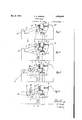
- Figure 7 is a sectional view taken on'the line 77 of Figures 3 and 4. V
- my improved track brake includes supporting means or base 6 disposed transversely of the rail 7" and formed withbearing faces (2 and (Z, the rail being disposed on any suitable fixed foundation r shown in this and the succeeding modifications as separate structural members supporting a wooden block on which the track rail is mounted.
- a brake shoe in the form of a rail f is fixed, the head of the said rail being in position for engaging the inner face of the car wheel
- the outer face of the car wheel is adapted to be engaged by a brake shoe a, which may likewise be in the form of a rail,
- the rail is carried by a rocking member or lever Z), the outer end 0 of which is rounded or'cam shaped.
- the inner end of the lever is supported on a spring 8 capable of holding the rail in braking position but yieldable to the pressure imposed by the car wheel on the flange a.
- the slide or base 6 may be. movl ably supported on a member or support such as shown in Frolich'Patent No. 1,635,989,
- a roller of substantially the disposition as indicated at p in Figure 5 may be provided to function similarly to the lever b of Figure 3.
- the roller is pivotally mounted as at 0 to the support 6 and contacts the member h'which loosely mounts the shoe a for translational movement to the support 6.
- the shoe a is resiliently supported on the support 6 through the springassembly a.
- the resilient support j may consist essentially of two side members If integrally attached to the support e as at t, each side member provided with arcuate slots 20 adapted to receive the bolt I), which extends through the lever 6 said bolt limiting therupward movement of the member 12 V I have also provided a spring :0 which will always bring the member 6 in readiness, as shown in Fig. 7, and is attached to the support 6- as at w, which is also applicable to the modification shown in Fig. 4.
- a roller such as shown at p in F1gure6 may be used iZO fLIIICi'JOIl 'lIl'El .mannersimilar to the lever t an Flgure 4.
- the re silient support 7' may be provided to maintain the lever Z1 and the member p in operative relation with respect to the support 0.
- the roller construction 79 such as shown in Figure 6, the necessity arises that the spring type of support be applied to the axis of the roller. That is, the member 2; will be on the axis of the member 39 by which the upward movement of this axis is limited by the pulling anchor, while the downward movement will be retarded by resting the roller on the hearing or support 0.
- the spring will always bring the roller 1? in readiness in the same manner as the spring members of the construction 6 aswill' readily be appreciated'.
- I claim 1 In track brake mechanism, the combination of a brake shoe associated with a rail, a support for said shoe, a member carrying said shoe and pivotally mounted on said support, and cam means disposed between said shoe and support whereby movement of said shoe imparts movement to said support.
- track brake mechanism the combination of a track rail, brake shoes disposed on both sidesof said rail for imparting braking action to wheels operative on said rail, a sup port for said shoes, means carrying said shoes pivotally mounted on said support, and cam means between one of said shoes and said support whereby movement of said shoe by said wheels moves said support to move said other shoe to braking position.
- track brake mechanism In track brake mechanism, the combination of a track rail, brake shoes disposed on both sides of said rail for imparting braking action to wheels operative on said rail, a support for said shoes, supporting means between said support and one of said shoes, and means including a cam disposed between one of said shoes and said support whereby said shoe is depressedin a direction substantially parallel to and by a wheel operating along tion of a brake shoe associated with a rail, a
- support for said shoe supporting means be tween said support and shoe, and means including a pluralityv of cams disposed between said shoe and support whereby movement of said shoe is imparted to said support.
- track brake mechanism the combination of a track rail, brake shoes disposed on both sides of said rail for imparting braking action to wheels operative on said rail,
- track brake mechanism the combination of a track rail, brake shoes disposed on both sides of said rail for imparting braking action to wheels operative on said rail, a support for said shoes selectivelyjmovable to effective braking position, resilient means for maintaining one of said brake shoes in wheel engaging position, and cam means between said shoe and said support'whereby movement of said shoe by said wheels-moves said support to move said other shoe to braking position.
- a brake shoe associated with a rail a support for said shoe, andmeans connecting said support and shoe whereby said shoe is depressed in a direction substantially parallel to and by a wheel operating along said rail
- said means including a member pivotally mounted with respect to said shoe and co operating therewith and contacting said support, and a shoe fixed to said support on the opposite side of said rail from said first named shoe and movable into wheel braking position by movement of said first named shoe.
- a brake shoe associated with a rail, a support for said shoe, and means connecting said support and shoe whereby said shoe is depressed in a direction substantially parallel to and by a wheel operating along said rail, said means including a member in rolling contact with said support and between said shoe and support.
- a brake shoe associated with arail a movable support for said shoe, means connecting said support and shoe whereby said shoe is depressed in a direction substantially parallel to and by a wheel operating along said rail, said means including a member secured to said shoe and loosely connected for translational movement to said support, and
- a brake shoe associated with a rail, a support for said shoe, means connecting said support and shoe whereby said shoe is depressed in a direction substantially parallel to and by awheel operating along said rail, said means including a member secured to said shoe and loosely connected to said support, and ,a member in rolling contact with said last named member and support.
- track brake mechanism the combination of a track rail, brake shoes disposed on both sides of said rail for imparting braking action to wheels operativeon said rail, a support for said shoes, supporting means between said support and one of said shoes, and means disposed between one of said shoesand said support and including a member loosely pivoted to said support for sliding movement with respect thereto whereby said shoe is depressed in a direction substantially parallel to and by a wheel operating along said rail and said other shoe is moved to braking. position, said other shoe being fiXeCl to said support.
Landscapes
- Engineering & Computer Science (AREA)
- Mechanical Engineering (AREA)
- Braking Arrangements (AREA)
Description
K. E. WENZEL May 2, 1933.
TRACK BRAKE 2 Sheets-Sheet 1 Filed Oct. 18, 1926 y 1933- Y K. E. WENZEL 1,906,348
TRACK BRAKE Filed Oct. 1926 2 Sheets-Sheet 2 JHUST'ZZET'I Karl E r1161? wen eil.
BJJWM Patented May 2, 1 933 unites sT TEs masts PATE T me KARL ERNST WENZEL, or imlvrnonn-onrnn-nnlnn;'snnmnnir, rissrenon, BY Mnsnn ASSIGNMENTS, TO. THE HANNAUEE one nn'raannn cor/Iran's, or .onronoo; ILLINOIS, A consort-a 161% or rLmNoIs TRACK BRAKE Application filed October 1a, 1926, Serial No. 142,2224, and in Gelmany October as, 1925".
My invention relates to improvements in track brakes for railways, and more particularly in track brakes comprising a pair of brake shoes located at opposite sides of each rail, one or both shoes being rockingly mounted and one having a flange on which the wheel of the vehicle to be braked rolls, so as to de-' press the brake shoe to force the sameinto braking contact with the side face of the wheel, the braking power depending onthe pressure of the car wheel-on the flange. An object of these improvementsis to provide a brake of this type in which the braking action is improved, and with this object in view my invention consists in supporting a rocking member cooperating with the brake shoe so that it is capable of rolling with its end on its support. For the purpose ofvexplaining the Figures 3 and 4 of modified forms of the 'de I vice.
Figure 7 is a sectional view taken on'the line 77 of Figures 3 and 4. V
' In the modification shown in Figure 1 my improved track brake includes supporting means or base 6 disposed transversely of the rail 7" and formed withbearing faces (2 and (Z, the rail being disposed on any suitable fixed foundation r shown in this and the succeeding modifications as separate structural members supporting a wooden block on which the track rail is mounted. To the face (Z a brake shoe in the form of a rail f is fixed, the head of the said rail being in position for engaging the inner face of the car wheel The outer face of the car wheel is adapted to be engaged by a brake shoe a, which may likewise be in the form of a rail,
which rail however is located so that it engages the car wheel with the side of its head, and so that its flange a 'is in position whereby the'car wheel, moving through the track brake, rolls thereon. The rail (1 is carried by a rocking member or lever Z), the outer end 0 of which is rounded or'cam shaped. The inner end of the lever is supported on a spring 8 capable of holding the rail in braking position but yieldable to the pressure imposed by the car wheel on the flange a. The slide or base 6 may be. movl ably supported on a member or support such as shown in Frolich'Patent No. 1,635,989,
granted July 19, 1927, adapted to be raised by mechanism such as shown in this patent, to move the shoes from inoperative position to an operative position with respect to the rails 1- whereby car wheels operating along the rails 7 may be contacted by said shoes to effect braking action. I i
iVhen a car moves through the track brake a when the brake is inoperative position, the
wheels roll on the flange a. Thereby the rail a isflforceddownwardly, and by reason of the toggle action of the lever Z) the braking pressure of the head a .onthe wheel 9 isfin creased according to the weight of the'car. In applying the brakes, it will be seen that the shoe a is pressed toward the left, as viewed in Figure 1, thereby moving or tending. to move the slide'c toward the left to apply braking pressure through the shoe 7 to the wheel 9. hen theslide is in lowered inoperative position, the wheels pass through the brake mechanism clear of the shoes whereby no operation is effected. 1
In Figure 2, I have shown a modification in which the rocking lever b is not directly connected to the rail (1, but in which. it is jointed by a bolt 2' to an arm h of a member havlng a part'lc directed downwardly and engaging a pm n mounted on the slide or base e-through a vertically disposedslot'r rzh Otherwise the construction'is the same as the rail a, the rail normally being resiliently supported by spring 8 provided on the slide and engaging bracket .2 carried by member 7b. In operation of this modification, it will be assumed that the lifting mechanism for the slide 6 is similar to that indicated in connection with the modification illustrated in Figure l,;. then when the slide has been disposed in position where the shoes "areioperative to'eiicct braking operation of'thewheel g, the shoe a is engageable by the wheel 9. It will be understood that the shoe 0; in this and the succeeding modifications is maintained in a raised position with respect to the slide 6 by means such as a spring 8 disposed between bracket 2 and slide 6 as explained above, i'.'e., in a position where the pin n contacts the lower part of the slot m! l/Vheel g contacting shoe 0; tends to move the slide e toward the left, as viewed in Figure 2, through the lever o to thereby set the shoe 7. Contact between the lower flange of the shoe a moves said shoe downwardly, rocking movement being eifected through the cam a and the surface cl, the shoe a moving downwardly substantially parallel to the rail 1" dueto the guide m and the rolling contact between 0 and cl. 7 s
The modification shown in Figure 3 is similar to the one shown in Figure 2, with the exception, however, that thelever is jointed or pivoted to the slide or base 6 by means of a bolt 0, and engages the arm h with a rounded or cam end 0, the said rounded end being an arc of a circle concentric with the bolt 0.
' As a matter offact, in lieu of the lever b a roller of substantially the disposition as indicated at p in Figure 5 may be provided to function similarly to the lever b of Figure 3. In the construction as shown in Figure 5 the roller is pivotally mounted as at 0 to the support 6 and contacts the member h'which loosely mounts the shoe a for translational movement to the support 6. The shoe a is resiliently supported on the support 6 through the springassembly a. While the member 6 in the construction'shown in'Figure 3 will be kept inworking contact with the element 72, by friction, the position of the member 6 can be assured by the provision of the resilient support The resilient support j may consist essentially of two side members If integrally attached to the support e as at t, each side member provided with arcuate slots 20 adapted to receive the bolt I), which extends through the lever 6 said bolt limiting therupward movement of the member 12 V I have also provided a spring :0 which will always bring the member 6 in readiness, as shown in Fig. 7, and is attached to the support 6- as at w, which is also applicable to the modification shown in Fig. 4.
- In the modification shown in Figure 4:, the
of tl1 e lever b a roller such as shown at p in F1gure6 may be used iZO fLIIICi'JOIl 'lIl'El .mannersimilar to the lever t an Flgure 4.
Asin the case of the lever 6 both in the construction shown in Figures 4 and 6, the re silient support 7' may be provided to maintain the lever Z1 and the member p in operative relation with respect to the support 0.
and the supporting member h. In using the roller construction 79 such as shown in Figure 6, the necessity arises that the spring type of support be applied to the axis of the roller. That is, the member 2; will be on the axis of the member 39 by which the upward movement of this axis is limited by the pulling anchor, while the downward movement will be retarded by resting the roller on the hearing or support 0. The spring will always bring the roller 1? in readiness in the same manner as the spring members of the construction 6 aswill' readily be appreciated'.
While in describing the invention referencehas been made to particular examples embodying the same, I wish it to be understood that myinvention is not limited to the constructions shown in the drawings, and that various changes be made in the general arrangement of the apparatus and the construction of its parts without departing from the invention.
I claim 1. In track brake mechanism, the combination of a brake shoe associated with a rail, a support for said shoe, a member carrying said shoe and pivotally mounted on said support, and cam means disposed between said shoe and support whereby movement of said shoe imparts movement to said support.
2. In track brake mechanism, the combination of a track rail, brake shoes disposed on both sidesof said rail for imparting braking action to wheels operative on said rail, a sup port for said shoes, means carrying said shoes pivotally mounted on said support, and cam means between one of said shoes and said support whereby movement of said shoe by said wheels moves said support to move said other shoe to braking position.
'3; In track brake mechanism, the combination of a track rail, brake shoes disposed on both sides of said rail for imparting braking action to wheels operative on said rail, a support for said shoes, supporting means between said support and one of said shoes, and means including a cam disposed between one of said shoes and said support whereby said shoe is depressedin a direction substantially parallel to and by a wheel operating along tion of a brake shoe associated with a rail, a
support for said shoe, supporting means be tween said support and shoe, and means including a pluralityv of cams disposed between said shoe and support whereby movement of said shoe is imparted to said support.
5. In track brake mechanism, the combination of a track rail, brake shoes disposed on both sides of said rail for imparting braking action to wheels operative on said rail,
a support for said shoes selectively movable to eilective braking position, and cam means between one of said shoes and said support whereby movement of said shoe by said Wheels moves said support to move said other shoe to braking position. H v
6. In track brake mechanism, the combination of a track rail, brake shoes disposed on both sides of said rail for imparting braking action to wheels operative on said rail, a support for said shoes selectivelyjmovable to effective braking position, resilient means for maintaining one of said brake shoes in wheel engaging position, and cam means between said shoe and said support'whereby movement of said shoe by said wheels-moves said support to move said other shoe to braking position.
7. In track brake mechanism, the combination of a brake shoe associated with a rail, a support for said shoe, andmeans connecting said support and shoe whereby said shoe is depressed in a direction substantially parallel to and by a wheel operating along said rail, said means including a member pivotally mounted with respect to said shoe and co operating therewith and contacting said support, and a shoe fixed to said support on the opposite side of said rail from said first named shoe and movable into wheel braking position by movement of said first named shoe.
8. In track brake mechanism, the combination of a brake shoe associated with a rail, a support for said shoe, and means connecting said support and shoe whereby said shoe is depressed in a direction substantially parallel to and by a wheel operating along said rail, said means including a member in rolling contact with said support and between said shoe and support.
9. In track brake mechanism, the combination of a brake shoe associated with arail, a movable support for said shoe, means connecting said support and shoe whereby said shoe is depressed in a direction substantially parallel to and by a wheel operating along said rail, said means including a member secured to said shoe and loosely connected for translational movement to said support, and
a shoe fixed to said support on the opposite side of said rail from said first named shoe, and movable into wheel braking position by movement of said first named shoe.
10. In track brake mechanism, the combination of a brake shoe associated with a rail, a support'for said shoe, means connecting said support and shoe whereby said shoe is depressed in a direction substantially parallel to and by a wheel operating along said rail, said means includmg a member secured to said shoe and loosely connected to sald support. and a member pivotedto said last named member and contacting said support.
11. In track brake mechanism, the combination of a brake shoe associated with arail, a support for saidshoe, means connecting said support and shoe whereby said shoe is depressed in adirection substantially par-' allel to and by a wheel'operating along said rail', said means including a member secured to said shoe and loosely connected to said support, and a member pivoted to said. supportand freely contacting said last named member. v
12. In track brake mechanism, the combination of a brake shoe associated with a rail, a support for said shoe, means connecting said support and shoe whereby said shoe is depressed in a direction substantially parallel to and by awheel operating along said rail, said means including a member secured to said shoe and loosely connected to said support, and ,a member in rolling contact with said last named member and support.
18. In track brake mechanism, the combination of a track rail, brake shoes disposed on both sides of said rail for imparting braking action to wheels operativeon said rail, a support for said shoes, supporting means between said support and one of said shoes, and means disposed between one of said shoesand said support and including a member loosely pivoted to said support for sliding movement with respect thereto whereby said shoe is depressed in a direction substantially parallel to and by a wheel operating along said rail and said other shoe is moved to braking. position, said other shoe being fiXeCl to said support.
In testimony whereof I hereunto affix my s1gnature,
KARL ERNST WENZEL.
Applications Claiming Priority (1)
| Application Number | Priority Date | Filing Date | Title |
|---|---|---|---|
| DE1906348X | 1925-10-28 |
Publications (1)
| Publication Number | Publication Date |
|---|---|
| US1906348A true US1906348A (en) | 1933-05-02 |
Family
ID=7748673
Family Applications (1)
| Application Number | Title | Priority Date | Filing Date |
|---|---|---|---|
| US142284A Expired - Lifetime US1906348A (en) | 1925-10-28 | 1926-10-18 | Track brake |
Country Status (1)
| Country | Link |
|---|---|
| US (1) | US1906348A (en) |
-
1926
- 1926-10-18 US US142284A patent/US1906348A/en not_active Expired - Lifetime
Similar Documents
| Publication | Publication Date | Title |
|---|---|---|
| US1906348A (en) | Track brake | |
| US3196985A (en) | Railway braking apparatus | |
| US2068731A (en) | Car retarder for railroads | |
| US1714621A (en) | Gripper brake for railways | |
| US3111197A (en) | Lifting beam retarder for brake beam system | |
| US1906347A (en) | Track brake | |
| US1546620A (en) | Safety device for coaster cars | |
| US2724459A (en) | Track brake of the jaw type for railroad cars | |
| US2068754A (en) | Car retarder for railroads | |
| GB251371A (en) | Improvements in brakes for railway vehicles | |
| US2880822A (en) | Clamp-type track brake for railway vehicles | |
| US1511813A (en) | Friction chock for cars | |
| UA28030C2 (en) | Shoe type braking device for railroad mobile Facilities | |
| US1495320A (en) | Brake for railroad vehicles | |
| US2415263A (en) | Automatic balanced slide for mine cars | |
| US764667A (en) | Car-brake. | |
| SU410996A1 (en) | ||
| GB202892A (en) | Improvements in or relating to means for braking railway vehicles | |
| US2940544A (en) | Braking systems | |
| US1812691A (en) | Railway car retarder apparatus | |
| SU38191A1 (en) | Track braking | |
| US856738A (en) | Brake for railway-vehicles. | |
| US1801990A (en) | Weight automatic rail brake | |
| US330671A (en) | Device for arresting locomotives and cars | |
| US1153151A (en) | Car-brake. |