US1857783A - Mortising machine - Google Patents
Mortising machine Download PDFInfo
- Publication number
- US1857783A US1857783A US488602A US48860230A US1857783A US 1857783 A US1857783 A US 1857783A US 488602 A US488602 A US 488602A US 48860230 A US48860230 A US 48860230A US 1857783 A US1857783 A US 1857783A
- Authority
- US
- United States
- Prior art keywords
- frame
- cutting
- carriage
- clamping
- knife
- Prior art date
- Legal status (The legal status is an assumption and is not a legal conclusion. Google has not performed a legal analysis and makes no representation as to the accuracy of the status listed.)
- Expired - Lifetime
Links
- 238000005520 cutting process Methods 0.000 description 50
- 239000002023 wood Substances 0.000 description 5
- 238000010276 construction Methods 0.000 description 3
- 239000000463 material Substances 0.000 description 3
- 230000000295 complement effect Effects 0.000 description 2
- 241000726103 Atta Species 0.000 description 1
- 240000008881 Oenanthe javanica Species 0.000 description 1
- 241000297945 Sidera Species 0.000 description 1
- 229960001948 caffeine Drugs 0.000 description 1
- 230000006835 compression Effects 0.000 description 1
- 238000007906 compression Methods 0.000 description 1
- 101150089047 cutA gene Proteins 0.000 description 1
- 230000000694 effects Effects 0.000 description 1
- 239000011888 foil Substances 0.000 description 1
- 239000011121 hardwood Substances 0.000 description 1
- 230000004048 modification Effects 0.000 description 1
- 238000012986 modification Methods 0.000 description 1
- 229920000136 polysorbate Polymers 0.000 description 1
- 239000007779 soft material Substances 0.000 description 1
Images

Classifications
-
- B—PERFORMING OPERATIONS; TRANSPORTING
- B27—WORKING OR PRESERVING WOOD OR SIMILAR MATERIAL; NAILING OR STAPLING MACHINES IN GENERAL
- B27F—DOVETAILED WORK; TENONS; SLOTTING MACHINES FOR WOOD OR SIMILAR MATERIAL; NAILING OR STAPLING MACHINES
- B27F5/00—Slotted or mortised work
- B27F5/02—Slotting or mortising machines tools therefor
- B27F5/12—Slotting or mortising machines tools therefor for making holes designed for taking up fittings, e.g. in frames of doors, windows, furniture
Definitions
- Another object of the invention is to "provide a, mortising machine which may be quickly adjusted, by moving or exchanging the cutting tools, to adapt it'to cut of various sizes and shapest I
- a further object of the invention- is to pro videa mortising machine in which tlie'cutting knives can be easily removed for sharp ening'and quickly adjusted to their proper operating positions.
- Fig. 2 is aview in longitudinal section, taken on a plane represented bythe lineII II of Fig; 1, of the mortising niachineg-Fig 3 is a view" in cross section-taken'on the plane represented by the line IIIIII of Fig.1, showing more plainly the vertically disposed-cutter;
- Fig. is a view-in cross sectiontakenfonthe plane represented by the line IVIV of Fig. 1 showing the details of the mechanism for clamping thehorizontal cutter; Fig.
- Fig. 6 is a view in end elevation of the modified side cutting knife
- the mortising-machine is dept'hs' which are ordinarily met within ap Asshown, the machine is held in operating position by' means of a clamping mechanism that comprises stationary, clamping abut ⁇ ments 5 depending from eacliof 'theside rails 2 an'da cooperating iiiovablec'laniping meln 7 bolts extending through the side rails 27 ing bar or rod 7 is attached to the center of the clamping member and pa'sses through the end piece3 of the frame 1.
- a clamping mechanism that comprises stationary, clamping abut ⁇ ments 5 depending from eacliof 'theside rails 2 an'da cooperating iiiovablec'laniping meln 7 bolts extending through the side rails 27 ing bar or rod 7 is attached to the center of the clamping member and pa'sses through the end piece3 of the frame 1.
- the I adjusting bar 7 is provided with ratchet notches 8' which constitute a rack that is slidingly mounted in'the end piece 3 and 'disposed to be engaged by a ratchet pawl 9 there- I on that functions to hold theclamping memwork piece4 and to cut the bottom and sides of a mortise by means of a reciprocating mechber 6 against the workpiece 4.
- ratchet notches 8' which constitute a rack that is slidingly mounted in'the end piece 3 and 'disposed to be engaged by a ratchet pawl 9 there- I on that functions to hold theclamping memwork piece4 and to cut the bottom and sides of a mortise by means of a reciprocating mechber 6 against the workpiece 4.
- the ratchet pawl 9 In clamping a work piece 4 the ratchet pawl 9 is first moved out-of engagement with'the ratchet notches 8 to permit the movable clamping member 6 to-beseparated from the stationary clamping abutments' 5'. The machine may thenbe' placed on the work piece 4 with the stationary, clamping abutments 5 in engagement with one side thereofyand the movable clamping members 6 may be moved into engagement with theother side by permitting the ratchet rack8 to slide through the end piece 3. During this .movement .the
- -ratchet pawl 9 may be released and will be heldin contact with. the, ratchet teeth 8 by means of a suitable spring 11, but itcwill permit the clamp 6 to move into closed position by reason of the fact that: itwill ride over the sloping faces of the ratchet teeth8.
- the pawl ,9 will engage one of the'ratchet notches 8 and will preventmovement of the clamp in the other direction.
- the adjusting bar 7 is provided with a turnbuckle mechanism 12 thatcomprises a handle member or grip 13 having right and left-hand nternal threads in its respective ends'which engage complementary threads on the ends of two separate members 14 and 15 which make up the adjustingbar 7.
- a turnbuckle mechanism 12 thatcomprises a handle member or grip 13 having right and left-hand nternal threads in its respective ends'which engage complementary threads on the ends of two separate members 14 and 15 which make up the adjustingbar 7.
- the cutting portion of the mortising ma- 7 chine includes a horizontal cutting mecha- 'nism 21that isniounted in the end of the frame 1 opposite'that which'is occupied bv' the movable clamping member 6.
- the horizontal cutting mechan sm 21 comprises a plate orbase portion 22 of substantially rectangular shape disposed between theside rails 2 of the frame 1 and adj'acent the end 1 piece 3.
- the base 22 is adjustably supported within the frame 1 by means of upstruck lugs orears 23. at its corners, which are provided with vertically disposed slots 24 that engage and provided at their outer ends with wing nuts 26.
- a cutter carriage 27 In the center of the base member 22 there is slidingly mounted a cutter carriage 27 provided with a centrally disposed dependingguide 28 which engages a longitudinal slot 29 in the base 22 for permitting the carriage 27 to reciprocate along the longitudinal axisof the frame 1.
- the carriage 27 serves as the supporting member'for a 'bot tom cutting knifeor main chisel '31 and for a pairof Vertical side wall forming knives 32. These knives may be moved to engage the operating handle 38.
- the pinion 36 By means of the handle 7 38 the pinion 36 may be'oscillated'to transmit .to the rack 33 and vthe carriage 27 a reciprocating motion wherebythe bottom. cuttingchisel 31 and the side cuttingkniv-es 32,
- the handle 38 is provided witb a socket 39 that engages a stub lever 40 onthe pinion 36 in such mannerthat it maybe readily removed to substitute ahandle of different length.
- Such construction is de'sirable in the event that the mortising machine is to 1 be used on different kinds of wood, asa long,- er handle may be used; when cutting hard wood thanthe handle ordinarily, utilized in cutting'softmaterial.
- This adjustment may be made to adapt the machine to cutm'ortisesfor light orv heavy hinges as thecase may be, and it isapparent that one end of the base 22 maybe set. at a .difi'erent level thanthe other end to cause the chisel 31 to be tilted in suchvmannerthat-it will cut at an angle to the upper surface of the work piece,
- the carriage 27' is provided with two clamping members 45 that are dis'posedxto clamp be tween them, cutting'chisels 31 of different Widths.
- the clampingmembers 45 are slidably mounted on a transverse guide bar 46 thati-s secured near .thetop of an'upwardly projecting. boss 47 in the center of the carriage 2-7.
- a threaded operating rod 48 is journalled in the boss 47 beneath the rod 46.
- The-threads on the rod 48 at one side of the bracket 47 are right-hand threads.
- the side c1 1tting'knives32 may automatically assume their properlater; alpositions relative to the chisel 31, they are carried on upwardly extending portions "at the forward ends of the clamping members 45.
- the knives 32 are disposed in vertical guidew'ays and are held by'screws 51 that-pass through vertical slots in the clamping members 45'to permit the knives '32 to be adjusted "vertically; vFor cutting some materials, it may be found desirable to utilize rotatable side cutting knives or; discs 52, as shown in Figsr5 and 6, in'place'of the plain knives 32' 'To permit the forward edge of the chisel 31 to assume the proper position relative totheverticalside cutting knives 32, the chisel may bem'oved 'longitudinally of the carriage '27, after loosening the clamping members 45 t0 bring it tothe desired position.- w 1 In starting to "cut a mortise theentire car,- ri
- the knife 55- is of width sub- TOCUtPtll'GbLCkIOf the mortise and to de stantially equal to that of the chisel 31 and is slidingly mounted in a vertical 'guidway in a guide block56 that is mountedtransversely of'the frame 1
- a vertical guide lug 57 which-is slidingly mounted on the face of the guide block 56 in such manner thatit may be "moved relative theretofor adjusting the guideway to receive knives of different widths.”
- eachguide lug 57 may be heldin position by a bolt Y58 and wing nut '59.
- the blade-55' isprovided at its center with a verticallydisposed slot 6l through which a screw 62is inserted for retaining the blade in position and limiting'itsii ertical movement; I At the top'of theblade 55 there is secured'anioperatinglug 63thatis bent horizontally over achamber 64in the guide block 56.
- guide'block v'56' is; disposed to be adjustable longitudinally ofthe frame 1Q As shown in Fig. $1," the guide block is'provided with apair of al-ms or brackets 68 which are 'atta ched tol'the side opposite to that occupied by 'the knife 55 ande'xtend along the inner 7 sides of'the siderailsfl of the frame 1; At
- brackets 68 are "provided with elongated longitudinal slots that engage boltsf69 extending through the side rails 2 V and providedat-their outer ends with wing nuts 7 Oi
- Another pair of brackets '7 2 extend from the arms 68a11'd engagethe tops of the side rails 2 near the back of the block56., i 8
- brackets 72 are providecl with slots thatarefsomewhat shorter than the slotsin tlie armsf 68 andextend in the opposite direction], These slots receive bolts 73that extend vertically through the side rails 2 and that are provided with wing nuts 74. It is-apparent that, when the wing nuts 7 0 and 7 4 are loosened,'tlie guide block' 56 may be moved longitudinally of theframe 1 tofthe proper position for cutting theback of a mortise, where T it may be secured by tightening the 'lVhenl it'i'sdesired t 'changezthe knife 55,
- the plunger actuating lever this-may bereadily accomplished by moving the guide block 56 to the left, as shown in Figs. 1 and 2, such distance that the slots in the brackets 72 will become entirely disengaged from the bolts 73.
- the guide block 56,1nay be pivoted about the bolts 69 to permit it to move upwardly and towardsthe end of the frame 1.
- the guide block 56 may be conveniently adjusted or, if desired, it may be completely removed by simply lifting it in such manner that the slots in-the arms 68 will be disengaged from the bolts 69.
- V v In utilizing the mortising machine to cut again for a hinge, in a door for.example,'it is first applied to the work piecein the desired position and clamped in place by tightening the turnbuckle 12.
- the operating handle 66 isleft in the position shown in Fig. 2 and the-handle 38 is moved to the left, from the position there shown, to withdraw the hori' zontal cutting carriage 27.
- the handle 38 is pulled to the right, as shown in Fig. 2, to force the chisel 31 and side cut-ting knives 32 into the wood.
- the width of the mortise is; governed by the position of the guide'block 56, and means are p-rovided on the carriage 27 for engaging the guide block 56 to stop the movement of the chisel 31 and the knives 32' when their cutting edges arrive at the back of the mortise.
- the upwardly extending portions at the forward ends of the clamping members are provided with adjustable stop members 81 having longitudinal slots 82 by means of which they are held in position by the screws 7 51.
- the stop members 81 are disposed to engage the face of the guide'block 56 and they may be adjusted, by reason of the slots 82, to stop the edgeof the chisel 31 at the desired position relative to theplunger knife 55.
- the. carriage 27 may be withdrawn, leaving the resulting chip of wood in its original position.
- 66 is thrown over tothe right, as shown in Fig. 2, to bring the cam h1g6?" into contact with the operating lug 63 on the knife 55..
- the operating handle 38 may then be moved to the left to engage the lever66 and force exerted upon it to move the knife downward thereby completing the mortise.
- machine is capable of being adj ustedto adapt it to cut mortises of various lengths, widths and thicknesses, and for use on different types of structures, as well as on different materials.
- a mortising machine comprising, a frame, a knife-carrying mechanism adjustably mounted on the frame, a carriageslidingly mounted on the mechanism, a pair-of clamping members mounted on the carriage and adapted to clamp bottom cutting chisels of different widths, a chisel disposed between V the clamping members, and side cutting knives carried by the clamping members.
- a mortising machine comprising a frame, a cutter carriage slidingly mounted in the frame, a bottom cutting chisel, means on the carriage for clamping the bottom'cutting chisel, said clamping means being adjustable to clamp chisels of different widths, and side cutting knives carried by the clamping means whereby the knives are adjustable to correspond to the width of the chisel clamped therein.
- a mortising machine comprising 7 a frame, a cutter mechanism adj ustably mount ed on the frame,.means for operating thecutthe frame, and a guide :member for said plunger knife, said guide member'being adjustable relative to the frame and pivoted thereto to provide for easily adjusting the knife. 7
- a mortising machine comprising a frame, means for clamping the frame to the work, a knife-carrying mechanism jincludmg a carriage slidlngly mounted 1n the frame, a plurality of side cutting knives ad- '120 justably mounted on the carriage, a bottom cutting knife removably' and adjustably mounted inthe carriage, means; for-adjusting the carriage vertically and angular-1y relative to the frame, and meansfor moving the carriage to form the sides and-bottomofa 6.
- a mortising machine comprising- ;,.a
- a gaining machine comprising a frame, means for clamping the frame on a work piece, a vertically disposed cutter slidably mounted in the frame for cutting the back side of a mortise, a carriage slidably mounted in the frame for movement longitudinally thereof, a bottom cutter mounted in the carriage, individual side cutters adjustably mounted on the carriage, means for adjusting the carriage relative to the frame, and means for operating the cutters to cut the sides and bottom of a mortise.
- a mortising machine comprising a frame, a bottom cutting chisel slidingly carried by the frame, a plunger knife disposed on the frame at substantially right angles to the chisel, means for operating the chisel and knife, a fixed clamping member carried by the frame, a movable clamping member slidably mounted on the frame, a bar having means for exerting force on the movable clamping member, a ratchet rack on the bar,
- a ratchet pawl on the frame for engaging the rack to adjust the position of the movable clamping member.
- a rectangular frame comprising side rails and end pieces, stationary clamping means secured to the side rails, movable clamping means slidably mounted on the side rails for cooperating with the stationary means to clamp a work piece, a ratchet pawl mounted in an end piece of the frame, a bar having ratchet notches slidably mounted in the end piece in working relation to the pawl and connected to the movable clamping means for adjusting it, mechanism in the bar for operating the clamping means, a horizontal cutter carried by the frame, vertical cutters disposed in cooperative relation to the horizontal cutter, and means for operating the cutters.
- a mortising machine comprising a frame having side sills and end pieces, a stationary clamping member secured to the frame, a movable clamping member slidably mounted on the frame, a ratchet device disposed to adjust the position of the movable member, and means for clamping the movable member against a work piece.
- a mortlsing machine comprising a frame having side sills and end pieces, a stationary clamping member secured to the frame, a movable clamping member slidably mounted on the frame, a ratchet device disposed to adjust the position of the movable member, means for clamping the movable member against a work piece, a'cutter-carrying base adjustably mounted in the frame, a carriage slidingly mounted on the base,
- clamping members on the carriage for holdframe acarriage slidingly mounted on the a base, clamping members on the carriagefor holding cutters, a bottom cuttmg chlsel disposed between the clamplng members, side cutting chisels carried by the clamping members, means for reciprocating the carriage to form the bottom and sides of a mortise, a guide block adjustably carried by the frame, a plunger knife slidingly mounted in the guide block at substantially right angles to the chisel knife, and means for actuating the plunger knife to form the back side of the mortise.
- a mortising machine comprlsmg a frame, means on the frame for clamplng the machine to a work piece, a knife-carrying mechanism slidably mounted on the frame,
Landscapes
- Life Sciences & Earth Sciences (AREA)
- Engineering & Computer Science (AREA)
- Wood Science & Technology (AREA)
- Mechanical Engineering (AREA)
- Forests & Forestry (AREA)
- Dovetailed Work, And Nailing Machines And Stapling Machines For Wood (AREA)
Description
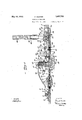
y 10, 1932- s.- HUNTER MORTISING MACHINE SSheets-Sheet.
Filed Oct.
INVENT'OR WITNES s. HUNTER 1,357,783
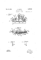
MORTISING MACHINE Filed Oct. 14. 1930 5 Sheets-Sheet 2 May 10, 1932.
INVENTOR 8M M Workin Patented May 10, 1932 r.
L UN1ranSTA-res SAMUEL HUNTER, or nnnnnvun, rnimsrnvenmghssrenon minimise & warm, or rrmrstennon, rnnnsynvanm, A CORPORATION-5013 mnnsYr-ivnmsi noit'rt'srne rule indi Application filedoetoliif al eao. seri m This invention relates, generally, to Wood machines .and particularly to machines for cutting gains or inortises in door jambs anddoors for receiving the leaves of hinges. a
The cutting-of hinge mortises by means of handtools, as is ordinarily done is a labo rious rocess and requires the exercise of coin 'sidera 1e skill and care'on the part-of the workman to insure a'neat and accurate job In this operation a number of separate tools includinga. hammer, chis'els, gauges and-a square are necessary. In manipulating these various separate tools considerable time is necessarily consumed in cutting each mortise, and in the construction of a large building the total time consulned in, cutting mortises for doors and doorways by hand may be large item. An object of theinvention, therefore, isto provide a machine for quickly and accurately cutting mortises in doors and door jambs.
' Another object of the invention is to "provide a, mortising machine which may be quickly adjusted, by moving or exchanging the cutting tools, to adapt it'to cut of various sizes and shapest I A further object of the invention-is to pro videa mortising machine in which tlie'cutting knives can be easily removed for sharp ening'and quickly adjusted to their proper operating positions. r 5' The foregoing andother objects, which will appear as the details oftheinvention are better understood, may be attained by means of the specific structure shown in the accompanyingdrawings in which Fig. lis a plan vieiw of a mortising machine constructed inaccordance with the present invention; Fig; 2 is aview in longitudinal section, taken on a plane represented bythe lineII II of Fig; 1, of the mortising niachineg-Fig 3 is a view" in cross section-taken'on the plane represented by the line IIIIII of Fig.1, showing more plainly the vertically disposed-cutter; Fig. is a view-in cross sectiontakenfonthe plane represented by the line IVIV of Fig. 1 showing the details of the mechanism for clamping thehorizontal cutter; Fig. '5 is a mortises 'view in side elevation of a side cutting knife whiclimay be'util-iied in the m ssing m chine; and Fig. 6 is a view in end elevation of the modified side cutting knife;
- I'n practicing thepresent invention a sup; porting irarneis utilized torcarryi'ng a honzontally disposed 'cuttin chisel and a vertically-disposed knife which are adapted to form respectivelythe-bottom and back oi a. mortise.---'I1i'e horizontally disposed 'cllisel'is' carried-on I a slidable" meinher' means of two clamps, each of whichcarries a. side cut ting knife that may be adjusted relative to the-horizontal; chisel for cutting the ends of the mortise. These various cutters are all so inounted'that they maybe readily removed 'for harpening or replacement, and theyare readily-adjIHstabIe'reIatiVe to each other'to permitthe machine to be used for cutting inqrtises'of thedi-iferentwidths, lengths and plying hinges to doors. n I Although the particularstructure shown in the drawings is; merely illustrative of the invention. and maybe modified in pract ce; it
constitutes a; practical embodiment of-thein J ventionand will be" particularly referred to in the tollowing' portions of'the specification;
' "Asclearly'shown in Fig.1, the mortising 1 is obvious thatthe frame lfinaybe' made entirely ofinetal or other material of channel or other. nSllltZlblQ shape gand that the general outline foil; the .frame may be departed from wthout changingthe functioning of the ap-,
pa e t v IniFigs. shownIdis'posed in operating position onfthe edge of a Wooden piece 4 that maybe taken torepresent aport'ion ofa dooravhichis to be nortisedfforreceiving a leatof a hinge.
1 and?v the mortising-machine is dept'hs' which are ordinarily met within ap Asshown, the machine is held in operating position by' means of a clamping mechanism that comprises stationary, clamping abut} ments 5 depending from eacliof 'theside rails 2 an'da cooperating iiiovablec'laniping meln 7 bolts extending through the side rails 27 ing bar or rod 7 is attached to the center of the clamping member and pa'sses through the end piece3 of the frame 1. As shown the I adjusting bar 7 is provided with ratchet notches 8' which constitute a rack that is slidingly mounted in'the end piece 3 and 'disposed to be engaged by a ratchet pawl 9 there- I on that functions to hold theclamping memwork piece4 and to cut the bottom and sides of a mortise by means of a reciprocating mechber 6 against the workpiece 4. I
In clamping a work piece 4 the ratchet pawl 9 is first moved out-of engagement with'the ratchet notches 8 to permit the movable clamping member 6 to-beseparated from the stationary clamping abutments' 5'. The machine may thenbe' placed on the work piece 4 with the stationary, clamping abutments 5 in engagement with one side thereofyand the movable clamping members 6 may be moved into engagement with theother side by permitting the ratchet rack8 to slide through the end piece 3. During this .movement .the
-ratchet pawl 9 may be released and will be heldin contact with. the, ratchet teeth 8 by means of a suitable spring 11, but itcwill permit the clamp 6 to move into closed position by reason of the fact that: itwill ride over the sloping faces of the ratchet teeth8. However, after the clamping member 6 hasv been moved to a positionadjacentthe' work piece 4 the pawl ,9 will engage one of the'ratchet notches 8 and will preventmovement of the clamp in the other direction. V 1
To effect the final clamping operation, the adjusting bar 7 is provided with a turnbuckle mechanism 12 thatcomprises a handle member or grip 13 having right and left-hand nternal threads in its respective ends'which engage complementary threads on the ends of two separate members 14 and 15 which make up the adjustingbar 7. In accordance with the well known operation ofturnbuckles it-is clear that the movable cl amping member 6 maybe moved to engage the work piece 4 with considerable force, by'turning the operating handle 13in the proper direction.
The cutting portion of the mortising ma- 7 chine includes a horizontal cutting mecha- 'nism 21that isniounted in the end of the frame 1 opposite'that which'is occupied bv' the movable clamping member 6. The horizontal cutting mechan sm 21 comprises a plate orbase portion 22 of substantially rectangular shape disposed between theside rails 2 of the frame 1 and adj'acent the end 1 piece 3. The base 22 is adjustably supported within the frame 1 by means of upstruck lugs orears 23. at its corners, which are provided with vertically disposed slots 24 that engage and provided at their outer ends with wing nuts 26.
In the center of the base member 22 there is slidingly mounted a cutter carriage 27 provided with a centrally disposed dependingguide 28 which engages a longitudinal slot 29 in the base 22 for permitting the carriage 27 to reciprocate along the longitudinal axisof the frame 1. The carriage 27 serves as the supporting member'for a 'bot tom cutting knifeor main chisel '31 and for a pairof Vertical side wall forming knives 32. These knives may be moved to engage the operating handle 38. By means of the handle 7 38 the pinion 36 may be'oscillated'to transmit .to the rack 33 and vthe carriage 27 a reciprocating motion wherebythe bottom. cuttingchisel 31 and the side cuttingkniv-es 32,
may be causedto engage the work piece 4.; i
. -As shown, the handle 38 is provided witb a socket 39 that engages a stub lever 40 onthe pinion 36 in such mannerthat it maybe readily removed to substitute ahandle of different length. Such construction is de'sirable in the event that the mortising machine is to 1 be used on different kinds of wood, asa long,- er handle may be used; when cutting hard wood thanthe handle ordinarily, utilized in cutting'softmaterial.
-To adjust the depth of thecut which'iis to be taken by the "bottom cutting. chisel--3l, it is simply necessary to adjust the position of the cutting mechanism base 22 relative torthe frame 1. q'As shown, the lugs 23 on the base 22 are providedtat their edges with rackiteeth 41-which engage small pinions 42. that are journalled. in the side rails 2. WVhenitis desired to adjust the position of the base 22, it is released from the frame'l by unscrewing the wing nuts 26, whereupon it may bere'adily raised or lowered by turning. pinions 42 by" means of a suitable Wrench *or key (not shown) which maybe applied to the square ends 43 of the ournals which carry the pinions. This adjustment may be made to adapt the machine to cutm'ortisesfor light orv heavy hinges as thecase may be, and it isapparent that one end of the base 22 maybe set. at a .difi'erent level thanthe other end to cause the chisel 31 to be tilted in suchvmannerthat-it will cut at an angle to the upper surface of the work piece,
a In the eventthat it is desired cuta I tise in what isknown asa rabbeted jambor .casing ha'ving a: raised piortion,.itji s simply-' a neoessa-ry to move the base'22 downwardly relative to the-frame l a suflicient distance to bring the-cutting edge of the chisel 31 below theedgeofthe j amb, whereupon itmay beach justed to cut a mortise of the desired depth.-
For adjusting the widthof the mortise, the carriage 27' is provided with two clamping members 45 that are dis'posedxto clamp be tween them, cutting'chisels 31 of different Widths. As shown, the clampingmembers 45 are slidably mounted on a transverse guide bar 46 thati-s secured near .thetop of an'upwardly projecting. boss 47 in the center of the carriage 2-7. For moving the clamping members 45 in such manner that they will be disposedsynunetrically relative to the centersof the carriage 27, a threaded operating rod 48 is journalled in the boss 47 beneath the rod 46. The-threads on the rod 48 at one side of the bracket 47 are right-hand threads. and those atthe other side of the bracket 47- are left-hand threads. These right and left-hand threads engage complementary threaded openings in the clampingmembers 45 insuch manner that when the rod 48 is turned, as by a crank 49, the clamping members 45 will be adjusted from or toward each other as :the case'may'be. T0 apply a bottom cutting chisel 31, it :is simply necessary to turn the rod 48 by-crank 49 until the clamping members 45 have been separated the required amount. I Thechi-sel 31'may then be placed in position and the rod 48 turned in-the opposite direction-to clamp it in place. a In. order that the side c1 1tting'knives32 may automatically assume their properlater; alpositions relative to the chisel 31, they are carried on upwardly extending portions "at the forward ends of the clamping members 45. As shown, the knives 32 are disposed in vertical guidew'ays and are held by'screws 51 that-pass through vertical slots in the clamping members 45'to permit the knives '32 to be adjusted "vertically; vFor cutting some materials, it may be found desirable to utilize rotatable side cutting knives or; discs 52, as shown in Figsr5 and 6, in'place'of the plain knives 32' 'To permit the forward edge of the chisel 31 to assume the proper position relative totheverticalside cutting knives 32, the chisel may bem'oved 'longitudinally of the carriage '27, after loosening the clamping members 45 t0 bring it tothe desired position.- w 1 In starting to "cut a mortise theentire car,- riage '27 maybe retracted bymeans ofthe rack 33 and the pinion 36 to a position in which the edgeof thechisel 31' will be back of the forward edge of the base plate 22 which is normally in engagement with the edge of the work piece 4. 'The carriage 27 maythen be moved forward tocut the bottom andjsides of :a mortiseas hereinbefore described. I
' provided. The knife 55- is of width sub- TOCUtPtll'GbLCkIOf the mortise and to de stantially equal to that of the chisel 31 and is slidingly mounted in a vertical 'guidway in a guide block56 that is mountedtransversely of'the frame 1 At each edge of the knife 55there is disposed a vertical guide lug 57 which-is slidingly mounted on the face of the guide block 56 in such manner thatit may be "moved relative theretofor adjusting the guideway to receive knives of different widths." =As shown, eachguide lug 57 may be heldin position by a bolt Y58 and wing nut '59. The blade-55'isprovided at its center with a verticallydisposed slot 6l through which a screw 62is inserted for retaining the blade in position and limiting'itsii ertical movement; I At the top'of theblade 55 there is secured'anioperatinglug 63thatis bent horizontally over achamber 64in the guide block 56. To forcethe' knife 55 in the upward direction'a' helical spring 65, of the compression resisting-type, is disposed within the chamber 64 and'in engagement with the lower surface of thelug 63." The'knife 55'Inay be 'forced downwardly to perform the cutting operation bymeans 'of an operating handle or plunger actuating lever'66 that is pivotal ly-mounted in brackets at the top of the gui'de'blook 56 in such 'manner'thatitmay beturned to bring" acamlug 67 thereon into engagement with the upper surface of th operating' lug 63 on-theknife 55. n To'providefor adjusting the machine'to out a "mortise of predetermined width, the
guide'block v'56'is; disposed to be adjustable longitudinally ofthe frame 1Q As shown in Fig. $1," the guide block is'provided with apair of al-ms or brackets 68 which are 'atta ched tol'the side opposite to that occupied by 'the knife 55 ande'xtend along the inner 7 sides of'the siderailsfl of the frame 1; At
their ends, the brackets 68 are "provided with elongated longitudinal slots that engage boltsf69 extending through the side rails 2 V and providedat-their outer ends with wing nuts 7 Oi Another pair of brackets '7 2 extend from the arms 68a11'd engagethe tops of the side rails 2 near the back of the block56., i 8
These brackets 72 are providecl with slots thatarefsomewhat shorter than the slotsin tlie armsf 68 andextend in the opposite direction], These slots receive bolts 73that extend vertically through the side rails 2 and that are provided with wing nuts 74. It is-apparent that, when the wing nuts 7 0 and 7 4 are loosened,'tlie guide block' 56 may be moved longitudinally of theframe 1 tofthe proper position for cutting theback of a mortise, where T it may be secured by tightening the 'lVhenl it'i'sdesired t 'changezthe knife 55,
the plunger actuating lever this-may bereadily accomplished by moving the guide block 56 to the left, as shown in Figs. 1 and 2, such distance that the slots in the brackets 72 will become entirely disengaged from the bolts 73. \Vhen in this position the guide block 56,1nay be pivoted about the bolts 69 to permit it to move upwardly and towardsthe end of the frame 1. When thus pivoted out of its normal position the guide block 56 may be conveniently adjusted or, if desired, it may be completely removed by simply lifting it in such manner that the slots in-the arms 68 will be disengaged from the bolts 69. V v In utilizing the mortising machine to cut again for a hinge, in a door for.example,'it is first applied to the work piecein the desired position and clamped in place by tightening the turnbuckle 12. The operating handle 66 isleft in the position shown in Fig. 2 and the-handle 38 is moved to the left, from the position there shown, to withdraw the hori' zontal cutting carriage 27. After the necessary adjustments have been made'to adapt the machine to cut a mortise of the desired dimensions, the handle 38 is pulled to the right, as shown in Fig. 2, to force the chisel 31 and side cut-ting knives 32 into the wood.
' As hereinbefore explained, the width of the mortise is; governed by the position of the guide'block 56, and means are p-rovided on the carriage 27 for engaging the guide block 56 to stop the movement of the chisel 31 and the knives 32' when their cutting edges arrive at the back of the mortise. As shown, the upwardly extending portions at the forward ends of the clamping members are provided with adjustable stop members 81 having longitudinal slots 82 by means of which they are held in position by the screws 7 51. The stop members 81 are disposed to engage the face of the guide'block 56 and they may be adjusted, by reason of the slots 82, to stop the edgeof the chisel 31 at the desired position relative to theplunger knife 55.
After the bottom and sides of the mortise have been formed, the. carriage 27 may be withdrawn, leaving the resulting chip of wood in its original position. To detach the chip and to form the back' of the mortise, 66 is thrown over tothe right, as shown in Fig. 2, to bring the cam h1g6?" into contact with the operating lug 63 on the knife 55.. The operating handle 38 may then be moved to the left to engage the lever66 and force exerted upon it to move the knife downward thereby completing the mortise.
From the foregoing description of the illustrated mortising machine and explanationof -its operation. it is apparent that by this inventi on I have provided ,a mortising machine which is convenient. to utilize and effective in cutting mortises in doors or door jambs. It is further apparentthatthismortising *ter mechanism,; a plunger knife carried by mortise.
machine is capable of being adj ustedto adapt it to cut mortises of various lengths, widths and thicknesses, and for use on different types of structures, as well as on different materials.
Although I havedescribed in detail a specific embodiment of the invention, it will be apparent to those skilled in the art of wood workingthat various modifications may be made in the general layout of this mortising machine and in the details of construction without departingfrom the spirit andscope of my invention as defined in the appended claims. I a. Iclaim: 1. In a mortising machine, in combination a frame, a cutter-carrying base adjustably mounted on the frame, a carriage slidably mounted on the base, clamping. means on the carriage, a bottom cutting chisel held by the clamping means, and side cutting knives carried by the clamping means.
2. A mortising machine comprising, a frame, a knife-carrying mechanism adjustably mounted on the frame, a carriageslidingly mounted on the mechanism, a pair-of clamping members mounted on the carriage and adapted to clamp bottom cutting chisels of different widths, a chisel disposed between V the clamping members, and side cutting knives carried by the clamping members.
3. A mortising machine comprising a frame, a cutter carriage slidingly mounted in the frame, a bottom cutting chisel, means on the carriage for clamping the bottom'cutting chisel, said clamping means being adjustable to clamp chisels of different widths, and side cutting knives carried by the clamping means whereby the knives are adjustable to correspond to the width of the chisel clamped therein. v
4; A mortising machine comprising 7 a frame, a cutter mechanism adj ustably mount ed on the frame,.means for operating thecutthe frame, and a guide :member for said plunger knife, said guide member'being adjustable relative to the frame and pivoted thereto to provide for easily adjusting the knife. 7
o. A mortising machine comprising a frame, means for clamping the frame to the work, a knife-carrying mechanism jincludmg a carriage slidlngly mounted 1n the frame, a plurality of side cutting knives ad- '120 justably mounted on the carriage, a bottom cutting knife removably' and adjustably mounted inthe carriage, means; for-adjusting the carriage vertically and angular-1y relative to the frame, and meansfor moving the carriage to form the sides and-bottomofa 6. A mortising machine comprising- ;,.a
frame, means .for clampingthe frame to the I piece to be mortised, a cutter carr a'ge,-slid-;
ingly mounted in the frame, side cutting knives adjustably mounted in said carriage for cutting the side walls of the mortise, a bottom wall cutting chisel also mounted in the carriage, means for adjusting the carriage relative to the frame, means for operating the carriage to form the sides and bottom of a mortise, and a plunger knife slidingly mounted in the frame for forming the rlelar wall of the mortise and for detaching the 0 1p.
7. A gaining machine comprising a frame, means for clamping the frame on a work piece, a vertically disposed cutter slidably mounted in the frame for cutting the back side of a mortise, a carriage slidably mounted in the frame for movement longitudinally thereof, a bottom cutter mounted in the carriage, individual side cutters adjustably mounted on the carriage, means for adjusting the carriage relative to the frame, and means for operating the cutters to cut the sides and bottom of a mortise.
8. A mortising machine comprising a frame, a bottom cutting chisel slidingly carried by the frame, a plunger knife disposed on the frame at substantially right angles to the chisel, means for operating the chisel and knife, a fixed clamping member carried by the frame, a movable clamping member slidably mounted on the frame, a bar having means for exerting force on the movable clamping member, a ratchet rack on the bar,
and a ratchet pawl on the frame for engaging the rack to adjust the position of the movable clamping member.
9. In a gaining machine, a rectangular frame comprising side rails and end pieces, stationary clamping means secured to the side rails, movable clamping means slidably mounted on the side rails for cooperating with the stationary means to clamp a work piece, a ratchet pawl mounted in an end piece of the frame, a bar having ratchet notches slidably mounted in the end piece in working relation to the pawl and connected to the movable clamping means for adjusting it, mechanism in the bar for operating the clamping means, a horizontal cutter carried by the frame, vertical cutters disposed in cooperative relation to the horizontal cutter, and means for operating the cutters.
10. A mortising machine comprising a frame having side sills and end pieces, a stationary clamping member secured to the frame, a movable clamping member slidably mounted on the frame, a ratchet device disposed to adjust the position of the movable member, and means for clamping the movable member against a work piece.
u f c I u I 11. A mortlsing machine comprising a frame having side sills and end pieces, a stationary clamping member secured to the frame, a movable clamping member slidably mounted on the frame, a ratchet device disposed to adjust the position of the movable member, means for clamping the movable member against a work piece, a'cutter-carrying base adjustably mounted in the frame, a carriage slidingly mounted on the base,
clamping members on the carriage for holdframe, acarriage slidingly mounted on the a base, clamping members on the carriagefor holding cutters, a bottom cuttmg chlsel disposed between the clamplng members, side cutting chisels carried by the clamping members, means for reciprocating the carriage to form the bottom and sides of a mortise,a guide block adjustably carried by the frame, a plunger knife slidingly mounted in the guide block at substantially right angles to the chisel knife, and means for actuating the plunger knife to form the back side of the mortise. V
13. A mortising machine comprlsmg a frame, means on the frame for clamplng the machine to a work piece, a knife-carrying mechanism slidably mounted on the frame,
bottom cutting and side cutting knives on .said mechanism, means for rec1procat1ng the mechanism for cutting the bottom and sides of a mortise, a plunger knife device for cutting the back of the mortise, said devicecomprising a guide block, supporting arms on the guide block pivotally and slidably connected to the frame whereby the block may be adjusted relative thereto or rotated therefrom for inserting a knife, a plunger knifeslidably mountedin the guide block, detachable means for securing the guide block in operating position on the frame, and means for v actuating the plungerknife to detachthe chip formed by the first-mentioned knife-car rying mechanism.
In testimony whereof, I sign my name.
SAMUEL -HUNTER.
Priority Applications (1)
| Application Number | Priority Date | Filing Date | Title |
|---|---|---|---|
| US488602A US1857783A (en) | 1930-10-14 | 1930-10-14 | Mortising machine |
Applications Claiming Priority (1)
| Application Number | Priority Date | Filing Date | Title |
|---|---|---|---|
| US488602A US1857783A (en) | 1930-10-14 | 1930-10-14 | Mortising machine |
Publications (1)
| Publication Number | Publication Date |
|---|---|
| US1857783A true US1857783A (en) | 1932-05-10 |
Family
ID=23940353
Family Applications (1)
| Application Number | Title | Priority Date | Filing Date |
|---|---|---|---|
| US488602A Expired - Lifetime US1857783A (en) | 1930-10-14 | 1930-10-14 | Mortising machine |
Country Status (1)
| Country | Link |
|---|---|
| US (1) | US1857783A (en) |
Cited By (3)
| Publication number | Priority date | Publication date | Assignee | Title |
|---|---|---|---|---|
| US2763300A (en) * | 1955-01-07 | 1956-09-18 | John A Comer | Hinge seat mortising tool |
| US2794460A (en) * | 1954-03-10 | 1957-06-04 | William L Grathwol | Hinge butt mortising machine |
| US3053292A (en) * | 1960-04-21 | 1962-09-11 | Schemitsch Ludwig | Mortising jig |
-
1930
- 1930-10-14 US US488602A patent/US1857783A/en not_active Expired - Lifetime
Cited By (3)
| Publication number | Priority date | Publication date | Assignee | Title |
|---|---|---|---|---|
| US2794460A (en) * | 1954-03-10 | 1957-06-04 | William L Grathwol | Hinge butt mortising machine |
| US2763300A (en) * | 1955-01-07 | 1956-09-18 | John A Comer | Hinge seat mortising tool |
| US3053292A (en) * | 1960-04-21 | 1962-09-11 | Schemitsch Ludwig | Mortising jig |
Similar Documents
| Publication | Publication Date | Title |
|---|---|---|
| US1857783A (en) | Mortising machine | |
| US400597A (en) | phillips | |
| US724966A (en) | Gaining-machine. | |
| US761861A (en) | Mortising device. | |
| US442878A (en) | Jacob geiger | |
| US394594A (en) | Stereotype-finishing machine | |
| US1430874A (en) | Machine for making door butt mortises | |
| US2794460A (en) | Hinge butt mortising machine | |
| US991062A (en) | Mortising-tool. | |
| US1306261A (en) | Machine fob cutting hides | |
| US465A (en) | Thomas peck | |
| US768058A (en) | Hinge-mortising machine. | |
| US1603652A (en) | Hinge-mortising tool | |
| US1754925A (en) | Mortise-cutting device | |
| US561770A (en) | Broom-trim ming machine | |
| US383692A (en) | Paper-cutting machine | |
| US1567669A (en) | Shank skiver | |
| US577868A (en) | Machine for cutting mortises for hinges in doors and door-jambs | |
| US348028A (en) | Peters | |
| US1079992A (en) | Curtain-stick machine. | |
| US1002599A (en) | Cutting-machine. | |
| US209452A (en) | Improvement in machines for cutting blanks for stove-pipe elbows | |
| US279899A (en) | wilson | |
| US1037909A (en) | Machine for creasing and cutting box-blanks. | |
| US86611A (en) | Improved machine for cutting tip leather-stock |