US1857066A - Blade sharpener - Google Patents
Blade sharpener Download PDFInfo
- Publication number
- US1857066A US1857066A US487312A US48731230A US1857066A US 1857066 A US1857066 A US 1857066A US 487312 A US487312 A US 487312A US 48731230 A US48731230 A US 48731230A US 1857066 A US1857066 A US 1857066A
- Authority
- US
- United States
- Prior art keywords
- casing
- sharpening
- blade
- flange
- elements
- Prior art date
- Legal status (The legal status is an assumption and is not a legal conclusion. Google has not performed a legal analysis and makes no representation as to the accuracy of the status listed.)
- Expired - Lifetime
Links
- 239000011521 glass Substances 0.000 description 2
- 229920001875 Ebonite Polymers 0.000 description 1
- 229920001967 Metal rubber Polymers 0.000 description 1
- 239000011324 bead Substances 0.000 description 1
- 230000000052 comparative effect Effects 0.000 description 1
- 238000010276 construction Methods 0.000 description 1
- 238000006073 displacement reaction Methods 0.000 description 1
- 238000003780 insertion Methods 0.000 description 1
- 230000037431 insertion Effects 0.000 description 1
- 239000000463 material Substances 0.000 description 1
- 239000002184 metal Substances 0.000 description 1
- 238000012986 modification Methods 0.000 description 1
- 230000004048 modification Effects 0.000 description 1
- 239000004575 stone Substances 0.000 description 1
Images
Classifications
-
- B—PERFORMING OPERATIONS; TRANSPORTING
- B24—GRINDING; POLISHING
- B24D—TOOLS FOR GRINDING, BUFFING OR SHARPENING
- B24D15/00—Hand tools or other devices for non-rotary grinding, polishing, or stropping
- B24D15/06—Hand tools or other devices for non-rotary grinding, polishing, or stropping specially designed for sharpening cutting edges
- B24D15/08—Hand tools or other devices for non-rotary grinding, polishing, or stropping specially designed for sharpening cutting edges of knives; of razors
- B24D15/088—Hand tools or other devices for non-rotary grinding, polishing, or stropping specially designed for sharpening cutting edges of knives; of razors with whetting leather
Definitions
- This invention relates to a sharpening device for edged tools, and is in the nature of an improvement upon my copending application, filed August 29, 1930, bearing Serial
- the present invention aims to generally improve a sharpening deviceof the indicated character by providing one of a plurality of elements having concave surfaces of relatively different characters, respectively wlth circumferentially extending corrugations or undulations, by virtue of which a more rapid and effectual sharpening of the edges is accomplished.
- the invention further aims to provide in a device of the indicated character, an element presenting a surface for initially honing or sharpening which in convex on its major portion and is provided with a remain- 29 ing fiat portion by virtue Of.Wl1lCl1 various forms of edged tools may be sharpened theresharpening surfaces of different characters,-
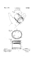
- Figure 1 is a perspective view illustrating the sharpening device constructed in accordance with the invention and the manner in which the same is used.
- Figure 2 is a transverse sectional view therethrough taken approximately on the line 22 of Figure 3.
- Figure 3 is a longitudinal sectional view take; approximately on the line 33 of Figure
- Referring to the drawings by characters of reference, 5 designates generally a cross sectionally elliptical tubular casing of any suitable material, such as metal or hard rubber, which is provided at one end with an inwardly extending marginal flange 6 and which is provided with opposite inwardly 6o projecting longitudinally extending ribs or heads 7.
- a pair of sharpening elementsdesignated respectively by the reference characters 8 and 9 aredesigned to snugly fit within the casing 5 between the ribs or beads 7.
- the flange 6 serves as an abutment means at one end of the casing 5 for limiting the insertion of the elements 8 and 9 within the casing and preventing displacement thereof through the flanged end.
- the element 8 which is preferably of glass, has its concaved inner sharpening surface 10 formed with circumferentially extending undulations or corrugations 11 which are extremely shallow but which function to more rapidly and effectually sharpen and finish the cutting edges of a blade when the same is reciprocated laterally I thereover.
- the element 9, which is preferably of stone, has its inner surface 12 for the major portion thereof concave, the remaining portion 13 being flat.
- This afi'ords surfaces of varying contours for use in connection with edged For instance, a double-edged safety razor blade will be sharpened on the surface 12 of the element 9 by reciprocating the same laterally in the manner illustrated in Figure 1, while the blades of knives, scissors or the like may be sharpened on the flat surface 13 of the element 9 by either a longitudinal, transverse or rotary movement.
- a cross sectionally elliptical tubular casing having longitudinally extending ribs projecting inwardly from the sides of the casing which are of lesser radius, a marginal inwardly projecting flange at one end of said casing and a pair of semi-elliptical sharpening elements removably fitted within the casing respectively on opposite sides of the ribs and in abutting relation to the marginal end flange.
- a cross sectionally elliptical tubular casing having longitudinally extending ribs projecting inwardly from the sides of the casing which are of lesser radius, a marginal inwardly projecting flange at one end of said casing and a pair of semi-elliptical sharpening elements removably fitted within the casing respectively on opposite sides of the ribs and in abutting relation to the marginal end flange, said elements being of different characters.
- a cross sectionally elliptical tubular casing having longitudinally extending ribs projecting inwardly from the sides of the casing which are of lesser radius, a marginal inwardly projecting flange at one end of said casing and a pair of semi-elliptical sharpening elements removably fitted within the casing respectively on opposite sides of the ribs and in abutting relation to the marginal end of flange, one of said elements being of glass and having an undulating sharpening surface.
- a cross sectionally elliptical tubular casing having longitudinally extending ribs projecting inwardly from the sides of the casing which are of lesser radius, a marginal inwardly projecting flange at one end of said casing and a pair of semi-elliptical sharpening elements removably fitted Within the casing respectively on opposite sides of the ribs and in abutting relation to the marginal end flange, one of said elements having a sharpening surface, the major portion of which is concave and the remaining portion of which is flat.
Landscapes
- Engineering & Computer Science (AREA)
- Mechanical Engineering (AREA)
- Knives (AREA)
Description
y 1932- N. SCHWARTZ 1,857,066
BLADE SHARPENER Filed Oct. 8, 1930 INVENTOR WITNESSES $6 {/1 a u D e/,1 ma rfz M ATTORNEYS Patented May 3, 1932 UNITED STATES NATHAN SCHWARTZ, 01 NEW YORK, N. Y.
BLADE SHARPENER Application filed October 8, 1930. Serial No. 487,812.
This invention relates to a sharpening device for edged tools, and is in the nature of an improvement upon my copending application, filed August 29, 1930, bearing Serial The present invention aims to generally improve a sharpening deviceof the indicated character by providing one of a plurality of elements having concave surfaces of relatively different characters, respectively wlth circumferentially extending corrugations or undulations, by virtue of which a more rapid and effectual sharpening of the edges is accomplished. v 1 The invention further aims to provide in a device of the indicated character, an element presenting a surface for initially honing or sharpening which in convex on its major portion and is provided with a remain- 29 ing fiat portion by virtue Of.Wl1lCl1 various forms of edged tools may be sharpened theresharpening surfaces of different characters,-
which elements are removably associated with the casing, in event of their renewal or replacement, when necessary. D
Other objects of the invention reside 1n the comparative simplicity of construction and mode of use of the device, the economy -w1th which the same may be provided and the general efiiciency derived therefrom.
With the above recited and other objects in view, reference is had to the following description and accompanying drawings, in which there is exhibited one example or embodiment of the invention, while the claims define the actual scope of the same.
In the drawings: 1
Figure 1 is a perspective view illustrating the sharpening device constructed in accordance with the invention and the manner in which the same is used.
Figure 2 is a transverse sectional view therethrough taken approximately on the line 22 of Figure 3.
tools of various types.
Figure 3 is a longitudinal sectional view take; approximately on the line 33 of Figure Referring to the drawings by characters of reference, 5 designates generally a cross sectionally elliptical tubular casing of any suitable material, such as metal or hard rubber, which is provided at one end with an inwardly extending marginal flange 6 and which is provided with opposite inwardly 6o projecting longitudinally extending ribs or heads 7. A pair of sharpening elementsdesignated respectively by the reference characters 8 and 9 aredesigned to snugly fit within the casing 5 between the ribs or beads 7. The flange 6 serves as an abutment means at one end of the casing 5 for limiting the insertion of the elements 8 and 9 within the casing and preventing displacement thereof through the flanged end. The element 8, which is preferably of glass, has its concaved inner sharpening surface 10 formed with circumferentially extending undulations or corrugations 11 which are extremely shallow but which function to more rapidly and effectually sharpen and finish the cutting edges of a blade when the same is reciprocated laterally I thereover.
The element 9, which is preferably of stone, has its inner surface 12 for the major portion thereof concave, the remaining portion 13 being flat. This afi'ords surfaces of varying contours for use in connection with edged For instance, a double-edged safety razor blade will be sharpened on the surface 12 of the element 9 by reciprocating the same laterally in the manner illustrated in Figure 1, while the blades of knives, scissors or the like may be sharpened on the flat surface 13 of the element 9 by either a longitudinal, transverse or rotary movement.
While there has been illustrated and described a single and preferred embodiment of the'invention, it is to be understood that no limitation is necessarilyintended to the precise structural details, but that variations and modifications which fall within the scope of the claims may be resorted to when de-* 1 sired.
What is claimed is:
1. In a blade sharpening device, a cross sectionally elliptical tubular casing having longitudinally extending ribs projecting inwardly from the sides of the casing which are of lesser radius, a marginal inwardly projecting flange at one end of said casing and a pair of semi-elliptical sharpening elements removably fitted within the casing respectively on opposite sides of the ribs and in abutting relation to the marginal end flange.
2. In a blade sharpening device, a cross sectionally elliptical tubular casing having longitudinally extending ribs projecting inwardly from the sides of the casing which are of lesser radius, a marginal inwardly projecting flange at one end of said casing and a pair of semi-elliptical sharpening elements removably fitted within the casing respectively on opposite sides of the ribs and in abutting relation to the marginal end flange, said elements being of different characters.
3. In a blade sharpening device, a cross sectionally elliptical tubular casing having longitudinally extending ribs projecting inwardly from the sides of the casing which are of lesser radius, a marginal inwardly projecting flange at one end of said casing and a pair of semi-elliptical sharpening elements removably fitted within the casing respectively on opposite sides of the ribs and in abutting relation to the marginal end of flange, one of said elements being of glass and having an undulating sharpening surface.
4. In a blade sharpening device, a cross sectionally elliptical tubular casing having longitudinally extending ribs projecting inwardly from the sides of the casing which are of lesser radius, a marginal inwardly projecting flange at one end of said casing and a pair of semi-elliptical sharpening elements removably fitted Within the casing respectively on opposite sides of the ribs and in abutting relation to the marginal end flange, one of said elements having a sharpening surface, the major portion of which is concave and the remaining portion of which is flat.
NATHAN SCHWARTZ.
Priority Applications (1)
| Application Number | Priority Date | Filing Date | Title |
|---|---|---|---|
| US487312A US1857066A (en) | 1930-10-08 | 1930-10-08 | Blade sharpener |
Applications Claiming Priority (1)
| Application Number | Priority Date | Filing Date | Title |
|---|---|---|---|
| US487312A US1857066A (en) | 1930-10-08 | 1930-10-08 | Blade sharpener |
Publications (1)
| Publication Number | Publication Date |
|---|---|
| US1857066A true US1857066A (en) | 1932-05-03 |
Family
ID=23935226
Family Applications (1)
| Application Number | Title | Priority Date | Filing Date |
|---|---|---|---|
| US487312A Expired - Lifetime US1857066A (en) | 1930-10-08 | 1930-10-08 | Blade sharpener |
Country Status (1)
| Country | Link |
|---|---|
| US (1) | US1857066A (en) |
Cited By (1)
| Publication number | Priority date | Publication date | Assignee | Title |
|---|---|---|---|---|
| US3199252A (en) * | 1963-06-12 | 1965-08-10 | John K Hanchey | Shaving blade conditioner |
-
1930
- 1930-10-08 US US487312A patent/US1857066A/en not_active Expired - Lifetime
Cited By (1)
| Publication number | Priority date | Publication date | Assignee | Title |
|---|---|---|---|---|
| US3199252A (en) * | 1963-06-12 | 1965-08-10 | John K Hanchey | Shaving blade conditioner |
Similar Documents
| Publication | Publication Date | Title |
|---|---|---|
| US9649749B2 (en) | Manual sharpener | |
| US3488845A (en) | Knife blade with double serrated edge | |
| US1911974A (en) | Method of producing serrated edges | |
| US1857066A (en) | Blade sharpener | |
| US1565680A (en) | Safety razor | |
| US2018985A (en) | Razor blade sharpener | |
| US699890A (en) | Knife-sharpener. | |
| US673933A (en) | Sharpener for scissors or knives. | |
| US2116582A (en) | Safety razor sharpener | |
| US564403A (en) | Knife or scissors sharpener | |
| US1916019A (en) | Blade sharpener | |
| US3250257A (en) | Rolling type pencil sharpener | |
| US609078A (en) | Sharpening device | |
| US1886483A (en) | Knife sharpener | |
| US602192A (en) | maillot | |
| US1083490A (en) | Knife-sharpener. | |
| US1154325A (en) | Pencil-sharpener. | |
| US1059016A (en) | Razor. | |
| US611369A (en) | Combined scissors and knife sharpener | |
| US1381334A (en) | Knife-sharpener | |
| US1683853A (en) | Razor-blade holder | |
| US616704A (en) | Shear-blade | |
| US874671A (en) | Clipper-sharpening machine. | |
| US2279634A (en) | Sharpener for safety razor blades | |
| US785264A (en) | Razor-strop. |