US1856836A - Method and apparatus for underground hydraulic mining - Google Patents
Method and apparatus for underground hydraulic mining Download PDFInfo
- Publication number
- US1856836A US1856836A US378601A US37860129A US1856836A US 1856836 A US1856836 A US 1856836A US 378601 A US378601 A US 378601A US 37860129 A US37860129 A US 37860129A US 1856836 A US1856836 A US 1856836A
- Authority
- US
- United States
- Prior art keywords
- working
- shaft
- tunnel
- mined
- mining
- Prior art date
- Legal status (The legal status is an assumption and is not a legal conclusion. Google has not performed a legal analysis and makes no representation as to the accuracy of the status listed.)
- Expired - Lifetime
Links
Images
Classifications
-
- E—FIXED CONSTRUCTIONS
- E21—EARTH DRILLING; MINING
- E21C—MINING OR QUARRYING
- E21C45/00—Methods of hydraulic mining; Hydraulic monitors
Definitions
- This invention relates to underground hydraulic mining', particularly to placer mining, and aims primarily to provide an improved method and apparatus for mining 5 .gold and other rare metals at depths too great for dredging or open cutting, which is much more efhcient and economical. in time and labor than the drifting or other methods heretofore employed for such purposes.
- Contemplated by the present invention is the provision of an underground hydraulic mining method and apparatus embodying certain novel features, principally among which are: Mining conditions are made to order; all apparatus employed is located underground; relatively few operators are necessary; mining operations are initiated at points furthest away from the mine shaft and are advanced towards the same; simultaneous thawing and cut-ting away the material containing the rare metals is eHected; the cutting water is utilized subsequent to cutting operations for conveying the mined material from the working face to the mine shaft and concurrently therewith for extracting the rare metals therefrom; the water is separated from the waste material or tailings and stored in a sump from which it is returned under pressure and in a heated condition to the working face, thus permitting of repeated or continuous use of such water for sluicing purposes; loss of water through absorption and in the waste material or tailings is slight; disposal of the Waste material or tailings is effected by hoisting or elevating the same to the surface, all of whichare important features of the invention and are to be correlated in the broad aim of
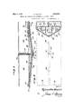
- Figure l is a vertical longitudinal section of a minecomprehended by the present invention.
- Fig. 2 is a plan view of the same, certain parts being shown in horizontal section for clarity of illustration.
- Fig. 3 is a vertical transverse section taken through line 3 3 of Fig. l.
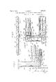
- Fig. 4 is an enlarged fragmentary vertical longitudinal section of the central portion of the mine.
- Fig. 5 is an enlarged fragmentary horizontal sect-ion taken through line 5-5 of Fig. 4.
- Fig. 6 is an enlarged longitudinal section of one of the mine tunnels, illustrating the manner of sluicing the pay dirt when the working face approaches the mine shaft.
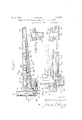
- Fig. 7 is a slightly modified form of means for hoisting the gravel from the mine.
- Fig. 8 isa diagrammatic horizontal 'section of the same taken through line 8 8. of Fig. 7, and
- Fig. 9 is a similar section of a modified form of gravel and pump sump arrangement.
- The. present method eliminates preliminary thawing of the material to be minedY when operating on frozen ground; eliminates pick and shovel work, wheelbarrows and cars, and top sluicing. Mining operations may be carried on twenty-four hours per day if desired, and equally well during summer and winter, particularly in the Territory of Alaska, where it has been necessary'and advisable in many instances, for economical and other reasons,
- the numeral 10 designates a section of ground toV be mined, which is preferably, but not necessarily, of rectangular formation, as more clearly illustrated in Fig. 2. ln practice such section is approximately eight hundredlfeet in length and five hundred feed in widtlnbut it is to be understood that these dimensions may be varied and are only furnished here as an example.
- a working shaft 11 is located substantially in the center of said section and is sunk into the bed rock designated by the numeral 12, which latter is cut into at or near the bottom of the shaft 11 to form a laterally extending passageway 13 enlarged at its outer end to form a pump chamber 14 and a longitudinally disposed water storage sump 15 extending therefrom.
- Upwardly sloping working tunnels 16v are next driven into the bed rock at opposite sides of the shaft 11, said tunnels being longitudinally and medially disposed relative to thek section 10, as more clearly ihustrated in Figs. 2 and' 3.v
- the slope of the tunnels is such that the outer ends of the same are above the bed rock l2 and at or near the ends of section 10, as clearly illustrated in Fig. 1'. ln practical operation l have found that a slope of eight per cent provides an excellent sluicing grade plus a rise of seven or eight feet in tlie total length of each tunnel for drainage purposes.
- Crosscuts 17 at the ends of the tunnels 16 are then driven into the material to be mined, such as gravel or pay dirt containing gold or other rare metals, such crosscuts being symmetrically arranged relative to theV tunnels lG and being made in order to initiate working faces 1S thereat.
- sectional sluice boxes 19 Installed in the tunnels 16 and extending substantially the entire length thereof are sectional sluice boxes 19 provided at their adjacent or inner ends with swinging tail boxes 20, Jfrom which the sluicing water and waste material or tailings are selectively deposited in hoppers or settling boxes 21, which are disposed side by side at the tunnel mouths and below the plane thereof, said tunnel mouths being suiliciently enlarged to accom modate said hoppers, in the manner more clear y shown in Fig. el.
- the hoppers 21 are i preferably formed with inner and uter com partments, the former being designed to receive the waste material and gravel and to permit the sluicing water to overflow into the latter.
- the inner compartments of each set of hoppers 21 are provided with gates 22:-
- each set of hoppers are adapted to be alternately hoisted to the surface by a hoisting bucket 26', actuated by any suitable means, not shown, each swinging tail box 2O permitting of the contents of one of its correlated hoppers being hoisted to the surface, while the other is being filled, as will be manifest and apparent by referring to Fig. 5, wherein a f.
- tailbox 20 is ⁇ illustrated 'in full lines: inone position and in dottedl'i'nes inits other position.
- a pump. 2,7 of any well; known type, ⁇ adapted. to be. driven by anv electric motor 28, or many other suitable manner, the suction side ofl saidpuinp -beiiigprovided with. a, suction pipe 29 having a terminal strainer 30.2 normally submersed. in the water storage sump 15,
- the. water in the storage sump 15 isY preferably heated by a steam pipe 36, which receives steam from any suitable source of supply, not
- both the sluicing water and gravity are utilised' in' conveying'thegravel or pay dirt through the sluiceY boxes.
- the water is 'eparated from the tailings and is conveyed by the fiume 25 toY the storage sump 15,
- the entire working faces 18 are gradually advanced due to the sluicing or washing action of the giants 35, which in the present instance are preferably arranged in echelon formation, so that such working faces are angularly and symmetrically cut relative to the longitudinal axis of the mine section 10, as more clearly
- the working faces 18 advancethe roof of the mine is quickly timbered in a well known manner, as by timbers or posts 37 to thereby properly protect t-he operators of the giants, which latter are moved up at intervals to the advancing faces 18, by adding pipe sections to the fluid pressureV or water supply pipes 32, as will be manifest and evident.
- the working faces 18 are in proximity to the Working shaft 11 and at a predetermined distance therefrom longitudinally and centrally disposed reversely sloping channels 39 are cut in the floor of the drift from said working faces to the nearest chutes 38, and sluice boxes 40 positioned therein to receive the sluiced material and convey the same to said chutes, this for the purpose' Vof simplifying and expediting mining operations at or near the working shaft 11, which are carried on up to the latter.
- Figs. 7 and 8 I have illustrated a slightly modified method and apparatus for separating the water from the tailings oi gravel and for hoist-ing the latter to the surface, wherein the numeral 41 designates the working shaft, 42 the working tunnels, and 43 the sluice boxes located therein.
- the working shaft 41 is enlarged at the bottom to form a gravel or tailings storage sump 44 provided with a Weir 45 over which the water flows to a pump sump 46.
- the discharge from the sluice boxes 43 falls directly into the storage sump 44 and is removed or hoisted to the surface by a clam shell bucket 47 of suitable capacity, operable by means not shown.
- the water in the pump vsump 46 is heated bykorin pipe 48 and is returned under pressure from said sump to the working faces by an electrically driven pump 49.
- Fig. 9 a still further modified type'of pump sumpV is illustrated, wherein the numeral 50 designates the Working tunnels, 51 the gravel storage sump at the bottomof the working shaft, not shown, and 52 an overflow weir for the water to pass to a pump sump 53.
- the present method and apparatus for underground hydraulic mining is particularly adaptable and especially suitable for work ⁇ ing low grade frozen placers, inasmuch as the cost of installation and operation is comparatively low.
- Y y i By locating the working shaft 11 in the center ofthe section 10 and providing two working tunnels for simultaneously conducting mining operations from both ends of said section, as herein vshown and described, itwill be obvious and apparent that such section is very rapidly and expeditiously mined. Also by starting at the outer ends of the section l0 and Working inwardly, as herein set forth, the mined portions need never be entered again by the workmen, thus materially decreasing danger tothe latter in the event of cave-ins occurring in such portions.
- the present method and apparatus is simple and economical to install and operate; permits locating the pump, giant-s and water supply underground in a complete compact unit; permits the sluicing water to be used over and over againindefinitely, as loss of same through absorp-v tion or in the tailings is comparatively slight; permits the sluicing water being utilized for several purposes, first to simultaneously thaw and cut the material to be mined, and second to simultaneously convey and separate the gold or other rare metalsfrom the mined material; vand permits selecting or making any suitable sluicing'grade'.
- VIVhile I have herein shown and described i the invention with sufficient detail to enable those skilled in the art to which it pertains 4 rese-,aaai
- a method of underground hydraulic mining consisting in sinkinga workingshaft7 drivinga tunnel: from said' shaftl adjacent the bottom thereof, driving-a cross-cut at the ing the fluid underpressure to the workingr face,
- a methodf of underground hydraulic mining consisting in sinking awork shaft into-the bed rock, driving a tunnelY from said shaft through the bed rock, driving a crosscut adjacent the end of'said tunnel and' immediately abovethe bed rock to establish a workingl face thereat, utilizing fluidi pressure for cutting away the material to be mined, utilizingthe ilu-id to convey'the mined material to. the working shaft and simultaneously therewith extracting the rare metals therefrom, separating the fluid from the waste material', elevating the latter-to the surface, and returning the fluid under pressure to the working face.
- A' methodV of underground hydraulic mining consisting in sinking a workingushaft, driving an upwardly sloping tunnel from said shaft, driving a cross-cut adjacent the end of said tunnel toestablish aworking faceV thereat, utilizing Huid pressure for ⁇ cutting away the material to be mined, utilizing the fluid toy convey the mined material to the working shaft" and simultaneously tl'ierewith separating the rare metals therefrom, separating the fluid from the waste-material, ele-A vating the latter tothe surface, and returning the fluid under pressure to the working face.
- a method of undergroundl hydraulic mining consisting in. sinkingl a; working 'shaft ⁇ v into the bed rock, driving any upwardly sloping tunnel through the bed rockt to tl e material to be minedinitiating a; workin-g face-y in said'material, utilizing fluidpressure for cutting away the latter, utilizing the liuidtoy convey the mined material to the working shaft and toextract the rare metals there'- from, separating the fluid from the; waste material, elevating thek latter to. the surface, and returning the fluid under pressure tothe working face.
- al method consisting in sinking a working shaft, driving a gravity tunnel from said shaft to: the material to be mined, initiating a working face thereat mining said material in the direction of said shaft, and cutting chutes.
- methodA consisting ⁇ in sinking a working shaft into the bed rock, driving a tunnel with asluicing grade through the bed rock from said shaft to the material to be mined', initiating a working face thereat mining said material in the direction of said' shaft, and' cutting chutes at intervals in the bed rock from the operating level to said tunnel during advancement of mining operations.
- a working shaft In an underground hydraulic mine, the combination of a working shaft, a working tunnel extending therefrom, a working face having communication with said tunnel, fluid storage means in said mine, sluicing means adapted to receive fluid from said storage means for cutting away the material to be mined from said working face, means for conveying the mined material and fluid from the working face to the working shaft and simultaneously therewith extracting the rare metals from said material, means for separating the fluid from the waste material and returning such Huid to said storage means, and means for elevating the waste material to the surface.
Description
s. HOWELL May 3, 19.32.
ME'HOD AND APPARATUS FOR UNDERGROUND HYDRAULIC MINING Filed July 16, 1929 3 Sheets-Sheet l s. HOWELL METHOD AND APPARATUS FOR UNDERGROUND HYDRAULIC MIEING Filed July 16. 1929 I5 Shees-Sh'ee 2 L L E w G H METHOD ND APPARATUS FOR UNDERGROUND HYDRAULC MNUG Filed Julfy'7 16, 1929 3 Sheets-Shea?,
ww. w
a 1. (qb
Patented May 3, 1932 UNITED STATES SYLVESTER HOWELL, OF FAIRBANKS, ALASKA METHOD AND APPARATUS FOR UNDERGROUND HYDRAULIC MINING Application led July 16, 1929. Serial No. 378,601.
This invention relates to underground hydraulic mining', particularly to placer mining, and aims primarily to provide an improved method and apparatus for mining 5 .gold and other rare metals at depths too great for dredging or open cutting, which is much more efhcient and economical. in time and labor than the drifting or other methods heretofore employed for such purposes.
Contemplated by the present invention is the provision of an underground hydraulic mining method and apparatus embodying certain novel features, principally among which are: Mining conditions are made to order; all apparatus employed is located underground; relatively few operators are necessary; mining operations are initiated at points furthest away from the mine shaft and are advanced towards the same; simultaneous thawing and cut-ting away the material containing the rare metals is eHected; the cutting water is utilized subsequent to cutting operations for conveying the mined material from the working face to the mine shaft and concurrently therewith for extracting the rare metals therefrom; the water is separated from the waste material or tailings and stored in a sump from which it is returned under pressure and in a heated condition to the working face, thus permitting of repeated or continuous use of such water for sluicing purposes; loss of water through absorption and in the waste material or tailings is slight; disposal of the Waste material or tailings is effected by hoisting or elevating the same to the surface, all of whichare important features of the invention and are to be correlated in the broad aim of enhancing the efficiency of the method and apparatus.
The above, and additional features which will hereinafter be more specifically treated, are attained in the manner set forth in the pointed out in the claims, which are appended hereto and form partof this application.
With reference to the drawings, in which are illustrated several embodiments of the invention, and throughout the several views following specification and then more clearly of which like characters of reference designate similar parts: Q
Figure l is a vertical longitudinal section of a minecomprehended by the present invention.
Fig. 2 is a plan view of the same, certain parts being shown in horizontal section for clarity of illustration.
Fig. 3 is a vertical transverse section taken through line 3 3 of Fig. l.
Fig. 4 is an enlarged fragmentary vertical longitudinal section of the central portion of the mine.
Fig. 5 is an enlarged fragmentary horizontal sect-ion taken through line 5-5 of Fig. 4.
Fig. 6 is an enlarged longitudinal section of one of the mine tunnels, illustrating the manner of sluicing the pay dirt when the working face approaches the mine shaft.
Fig. 7 is a slightly modified form of means for hoisting the gravel from the mine.
Fig. 8 isa diagrammatic horizontal 'section of the same taken through line 8 8. of Fig. 7, and
Fig. 9 is a similar section of a modified form of gravel and pump sump arrangement.
Before taking up th-e detailed description of the drawings, a brief exposition of the advantages and benefits to be derived from the hydraulic method evolved by the present invention over drifting and other methods formerly employed will be undertaken. The. present method eliminates preliminary thawing of the material to be minedY when operating on frozen ground; eliminates pick and shovel work, wheelbarrows and cars, and top sluicing. Mining operations may be carried on twenty-four hours per day if desired, and equally well during summer and winter, particularly in the Territory of Alaska, where it has been necessary'and advisable in many instances, for economical and other reasons,
vwhen employing old methods to close down during the winter months. The temperature in any part of the min-e never falls below the freezing point, a feature of considerable importance to the operators. Operations can be carried on at least three or four times more rapidly than by the old methods. The eX- penditure ofeifort on the part of operators Los is materially reduced, inasmuch as cutting operations are performed by hydraulic giants, the mined material and water carried away by gravity, and the waste material mechanically hoisted to the surface.
Beginning now the more detailed description of the invention by reference to the accompanying drawings, the numeral 10 designates a section of ground toV be mined, which is preferably, but not necessarily, of rectangular formation, as more clearly illustrated in Fig. 2. ln practice such section is approximately eight hundredlfeet in length and five hundred feed in widtlnbut it is to be understood that these dimensions may be varied and are only furnished here as an example.
In commencing mining operations on the section 10 a working shaft 11 is located substantially in the center of said section and is sunk into the bed rock designated by the numeral 12, which latter is cut into at or near the bottom of the shaft 11 to form a laterally extending passageway 13 enlarged at its outer end to form a pump chamber 14 and a longitudinally disposed water storage sump 15 extending therefrom.
Upwardly sloping working tunnels 16v are next driven into the bed rock at opposite sides of the shaft 11, said tunnels being longitudinally and medially disposed relative to thek section 10, as more clearly ihustrated in Figs. 2 and' 3.v The slope of the tunnels is such that the outer ends of the same are above the bed rock l2 and at or near the ends of section 10, as clearly illustrated in Fig. 1'. ln practical operation l have found that a slope of eight per cent provides an excellent sluicing grade plus a rise of seven or eight feet in tlie total length of each tunnel for drainage purposes.
Installed in the tunnels 16 and extending substantially the entire length thereof are sectional sluice boxes 19 provided at their adjacent or inner ends with swinging tail boxes 20, Jfrom which the sluicing water and waste material or tailings are selectively deposited in hoppers or settling boxes 21, which are disposed side by side at the tunnel mouths and below the plane thereof, said tunnel mouths being suiliciently enlarged to accom modate said hoppers, in the manner more clear y shown in Fig. el. The hoppers 21 are i preferably formed with inner and uter com partments, the former being designed to receive the waste material and gravel and to permit the sluicing water to overflow into the latter. The inner compartments of each set of hoppers 21 are provided with gates 22:-
and a common gravel discharge spout 23, while the outer compartments of such hoppers ai'e provided with a common water discharge spout 24, from which the return sluicing water is discharged into a flume 25, which in turn empties into the sump 15. The contents of the inner compartments of each set of hoppers are adapted to be alternately hoisted to the surface by a hoisting bucket 26', actuated by any suitable means, not shown, each swinging tail box 2O permitting of the contents of one of its correlated hoppers being hoisted to the surface, while the other is being filled, as will be manifest and apparent by referring to Fig. 5, wherein a f.
Located in the pump chamber14isa pump. 2,7, of any well; known type,` adapted. to be. driven by anv electric motor 28, or many other suitable manner, the suction side ofl saidpuinp -beiiigprovided with. a, suction pipe 29 having a terminal strainer 30.2 normally submersed. in the water storage sump 15,
while the discharge side, ofthe pump is. pro,- videdy With a discharge pipe 31,. which extends to the shaft 11 andbranches thereat .toform pipes32, whichfextendthrough the tun.- nelsv 16 substantially the full length of the same. Connected'I to the outer endof.I each ofthe, pipes 32isa transversely disposed pipeV or linai'iifold 33 froiir which extendgbran'ches.
34 having hydraulic giants or sluic-ing monitorsl 35 connected, therewith.
When operating upon frozen, ground: the. water in the storage sump 15 isY preferably heated by a steam pipe 36, which receives steam from any suitable source of supply, not
shown.. In. this. connection it may be well.
to state, actual expericncehas shown. that, the temperature. off the water. for all prac,- tical p iirposesshould be equallt'o. or slightly above blood heat, such temperature being sufficient. to effectively obtainI- simultaneous. thawing and sluicing of frozen placers.
In carrying out the present. method-fol? lowing initiation of. the working faces 18 and. installation of the` hydraulic giants 35, the high pressure streams of water froinsuch giants rapidly sluice or wash. away the gravel or pay dirt from saidlfaces, which gravel or pay dirt is conveyed by the sluicing water into the sluice boxes 19' and during passage lierethrough, the goldr in such gravel or dirt is extracted therefrom in a well known manner, so thatv only the waste material or tailings isy deposited in one or the other of the hoppers associated with the particular sluice' boxf19. Itl is to be here noted that both the sluicing water and gravity are utilised' in' conveying'thegravel or pay dirt through the sluiceY boxes. In the hoppers 21 the water is 'eparated from the tailings and is conveyed by the fiume 25 toY the storage sump 15,
l `illustrated in Fig. 2.
wherein it is heated by the steam pipe 36 and wherefrom it is returned under pressure to the working faces 18 by the pump 27, while the tailings from alternate lioppers are hoisted to the surface by the bucket 26, all as hereinbefoie described.
It is of course apparent that the entire working faces 18 are gradually advanced due to the sluicing or washing action of the giants 35, which in the present instance are preferably arranged in echelon formation, so that such working faces are angularly and symmetrically cut relative to the longitudinal axis of the mine section 10, as more clearly As the working faces 18 advancethe roof of the mine is quickly timbered in a well known manner, as by timbers or posts 37 to thereby properly protect t-he operators of the giants, which latter are moved up at intervals to the advancing faces 18, by adding pipe sections to the fluid pressureV or water supply pipes 32, as will be manifest and evident.
Beginning with the initial working faces "18 and-continuing during sluicing or cutting operations of the gravel or pay dirt great care is taken to provide a slight grade both longitudinally and laterally on the floor of the drift, as more clearly illustrated in Fig.
"3, in order that the sluiced or cut material from the working faces will flow easily and rapidly to the tunnels 16 and into the sluice boxes 19 with the minimum impedance. To expedite and facilitate removal of the mined material from the floor of the drift during advancement of mining operations I have found it advisable and convenient to cut centrally aligned chutes 38 at intervals in the bed rock from the operating level to the tunnels 16 for the passage therethrough of said mined material to the sluice boxes 19. As each successive chute 38 is cut, as above described, that portion of the associated sluice box 19 extending beyond such chute may be dismantled or removed, there being no further use for the same in such location, see Fig. 6. In this connection, while I have shown the pipe 32, in Fig. 6, as extending l.the entire l-ength of the tunnel and return- "bent to extend to the advanced working face therein illustrated, it is to be understood that such pipe may be foreshoi'teiied if desired and passed up through any of the chutes 38, which feature will be obvious upon inspection.
IVhen the working faces 18 are in proximity to the Working shaft 11 and at a predetermined distance therefrom longitudinally and centrally disposed reversely sloping channels 39 are cut in the floor of the drift from said working faces to the nearest chutes 38, and sluice boxes 40 positioned therein to receive the sluiced material and convey the same to said chutes, this for the purpose' Vof simplifying and expediting mining operations at or near the working shaft 11, which are carried on up to the latter.
In Figs. 7 and 8, I have illustrated a slightly modified method and apparatus for separating the water from the tailings oi gravel and for hoist-ing the latter to the surface, wherein the numeral 41 designates the working shaft, 42 the working tunnels, and 43 the sluice boxes located therein. The working shaft 41 is enlarged at the bottom to form a gravel or tailings storage sump 44 provided with a Weir 45 over which the water flows to a pump sump 46. The discharge from the sluice boxes 43 falls directly into the storage sump 44 and is removed or hoisted to the surface by a clam shell bucket 47 of suitable capacity, operable by means not shown. The water in the pump vsump 46 is heated by asteain pipe 48 and is returned under pressure from said sump to the working faces by an electrically driven pump 49. c
In Fig. 9 a still further modified type'of pump sumpV is illustrated, whereinthe numeral 50 designates the Working tunnels, 51 the gravel storage sump at the bottomof the working shaft, not shown, and 52 an overflow weir for the water to pass to a pump sump 53.
The present method and apparatus for underground hydraulic mining is particularly adaptable and especially suitable for work` ing low grade frozen placers, inasmuch as the cost of installation and operation is comparatively low. Y y i By locating the working shaft 11 in the center ofthe section 10 and providing two working tunnels for simultaneously conducting mining operations from both ends of said section, as herein vshown and described, itwill be obvious and apparent that such section is very rapidly and expeditiously mined. Also by starting at the outer ends of the section l0 and Working inwardly, as herein set forth, the mined portions need never be entered again by the workmen, thus materially decreasing danger tothe latter in the event of cave-ins occurring in such portions. Manifestly, therefore, the present method and apparatus is simple and economical to install and operate; permits locating the pump, giant-s and water supply underground in a complete compact unit; permits the sluicing water to be used over and over againindefinitely, as loss of same through absorp-v tion or in the tailings is comparatively slight; permits the sluicing water being utilized for several purposes, first to simultaneously thaw and cut the material to be mined, and second to simultaneously convey and separate the gold or other rare metalsfrom the mined material; vand permits selecting or making any suitable sluicing'grade'.
VIVhile I have herein shown and described i the invention with sufficient detail to enable those skilled in the art to which it pertains 4 rese-,aaai
to: understand the same and: the principles involved, it is. tobe understood that there is. no intentional limitation herein to the specificmethod and precise detail-s of con-- y struction shown. and described, except: as expressly defined by the appended:V claims and that variousv modifications of the invention may be resorted towithout departing from` the spirit of the invention or the benefits derivable therefrom. It` isa-lso to be understood that certain features ofthe invention:
liereindisclosed mayv be employed in and with other' combinations than those shown and described.
What I claim as my invention and desire to. secure by Letters Patent is 1. A method of underground hydraulic mining consisting in sinkinga workingshaft7 drivinga tunnel: from said' shaftl adjacent the bottom thereof, driving-a cross-cut at the ing the fluid underpressure to the workingr face,
2; A methodf of underground hydraulic mining consisting in sinking awork shaft into-the bed rock, driving a tunnelY from said shaft through the bed rock, driving a crosscut adjacent the end of'said tunnel and' immediately abovethe bed rock to establish a workingl face thereat, utilizing fluidi pressure for cutting away the material to be mined, utilizingthe ilu-id to convey'the mined material to. the working shaft and simultaneously therewith extracting the rare metals therefrom, separating the fluid from the waste material', elevating the latter-to the surface, and returning the fluid under pressure to the working face.
3. A' methodV of underground hydraulic mining consisting in sinking a workingushaft, driving an upwardly sloping tunnel from said shaft, driving a cross-cut adjacent the end of said tunnel toestablish aworking faceV thereat, utilizing Huid pressure for` cutting away the material to be mined, utilizing the fluid toy convey the mined material to the working shaft" and simultaneously tl'ierewith separating the rare metals therefrom, separating the fluid from the waste-material, ele-A vating the latter tothe surface, and returning the fluid under pressure to the working face. y
4. A method of undergroundl hydraulic mining consisting in. sinkingl a; working 'shaft`v into the bed rock, driving any upwardly sloping tunnel through the bed rockt to tl e material to be minedinitiating a; workin-g face-y in said'material, utilizing fluidpressure for cutting away the latter, utilizing the liuidtoy convey the mined material to the working shaft and toextract the rare metals there'- from, separating the fluid from the; waste material, elevating thek latter to. the surface, and returning the fluid under pressure tothe working face.
5. In underground hydraulic mining, a method consisting in sinking a working shaft, driving a tunnel from said shaft' with a sluicing grade, driving a cross-cut at the end ofY saidv tunnel to establish a. working face thereat, and mining towardssaid shaft.
6. In underground hydraulic mining, a method consisting in sinking a working shaft into bedrock, and driving anl upwardly sloping tunnel from saidV shaft through said bed rock to the material to be mined, whereby said material is mined in the direction of the shaft and said tunnel is utilizedv for conveyingthe mined. material from the point of excavation to. they bottom of said working' shaft.
7.. In underground hydraulic mining,"a
method consisting in sinking a working shaftv in bed rock, driving a gravity tunnel from said shaft through said bed rock to the material-r to be'` mined, utilizing fluid under pressure for cutting away such materialy in' the direction of the shaft,.and utilizing the fluid: and tunnelgrade. for conveying the mined material from the pointof excavation tothe' bottom, of said workingshaft.
8. In underground hydraulic mining, al method consisting in sinking a working shaft, driving a gravity tunnel from said shaft to: the material to be mined, initiating a working face thereat mining said material in the direction of said shaft, and cutting chutes.
at intervals from the operating level to the gravity tunnel during advancement. of minmg operations. Y
9. In underground hydraulic mining, a.
methodA consisting` in sinking a working shaft into the bed rock, driving a tunnel with asluicing grade through the bed rock from said shaft to the material to be mined', initiating a working face thereat mining said material in the direction of said' shaft, and' cutting chutes at intervals in the bed rock from the operating level to said tunnel during advancement of mining operations.
10. In underground hydraulic mining, a
method consisting'in sinking a-working shaft,..
driving a gravityy working tunnel from said shaft to the materialto be mined, initiating a working face thereat mining said material in the directionA of said shaft, and establishing a slight grade longitudinally and laterally on the floor of the drift during mining operations for conveying the mined materia-l to said gravity tunnel.
1l'.` In underground hydraulic mining, a method' consistingin sinkingia working shaft, driving a gravity working tunnel from, said lao.
shaft to the material to be mined, initiating a working face thereat, cutting chutes at iiitervals from the operating level to the grav-A ity tunnel during advancement of mining operations, and finally at a. predetermined distance from said shaft establishing a reversely disposed sluicing grade from the operating level to the nearest chute, whereby the mined material is sluiced from the working face to the gravity tunnel.
12. In an underground hydraulic mine, the combinat-ion of a working shaft, a working face initiated at a distance therefrom and communicating therewith, fluid storage means in said mine, and sluicing means for cutting said work face in the direction of said shaft adapted to receive fluid from said storage means.
13. In an imderground hydraulic mine, the combination of a working shaft, a working tunnel leading from said shaft, a working face initiated at the outer end of said tunnel and communicating therewith, Huid storage means in said mine, sluicing means for cutting said working face in the direction of said shaft adapted to receive iuid from said storage means7 and means for returning the fluid to said storage means following sluieing operations.
14. In an underground hydraulic mine, the combination of a working shaft, a working tunnel extending therefrom, a working face having communication with said tunnel, fluid storage means in said mine, sluicing means adapted to receive fluid from said storage means for cutting away the material to be mined from said working face, means for conveying the mined material and fluid from the working face to the working shaft and simultaneously therewith extracting the rare metals from said material, means for separating the fluid from the waste material and returning such Huid to said storage means, and means for elevating the waste material to the surface.
15. In an underground hydraulic mine, the combination of a working shaft, a working face initiated at a distaznce therefrom and communicating therewith, fluid storage means in said mine, means for heating the fluid in said storage means, sluicing means adapted to receive heated fluid from said storage means for thawing and cutting away said working face in the direction of said shaft, and means for returning the fluid to said storage means.
In testimony whereof I aflix my signature.
SYLVESTER HOVELL.
Priority Applications (1)
| Application Number | Priority Date | Filing Date | Title |
|---|---|---|---|
| US378601A US1856836A (en) | 1929-07-16 | 1929-07-16 | Method and apparatus for underground hydraulic mining |
Applications Claiming Priority (1)
| Application Number | Priority Date | Filing Date | Title |
|---|---|---|---|
| US378601A US1856836A (en) | 1929-07-16 | 1929-07-16 | Method and apparatus for underground hydraulic mining |
Publications (1)
| Publication Number | Publication Date |
|---|---|
| US1856836A true US1856836A (en) | 1932-05-03 |
Family
ID=23493792
Family Applications (1)
| Application Number | Title | Priority Date | Filing Date |
|---|---|---|---|
| US378601A Expired - Lifetime US1856836A (en) | 1929-07-16 | 1929-07-16 | Method and apparatus for underground hydraulic mining |
Country Status (1)
| Country | Link |
|---|---|
| US (1) | US1856836A (en) |
Cited By (7)
| Publication number | Priority date | Publication date | Assignee | Title |
|---|---|---|---|---|
| US3349848A (en) * | 1965-10-24 | 1967-10-31 | Ernest E Burgh | Process for in situ retorting of oil shale |
| US3695711A (en) * | 1970-01-21 | 1972-10-03 | Wintershall Ag | Method of recovering underground deposits of soluble minerals, and apparatus for carrying out the method |
| US3870373A (en) * | 1974-04-15 | 1975-03-11 | Continental Oil Co | Underground coal slurry concentrating sump |
| US3934935A (en) * | 1974-08-26 | 1976-01-27 | Bechtel International Corporation | Hydraulic mining of oil bearing formation |
| US3981541A (en) * | 1974-04-15 | 1976-09-21 | Continental Oil Company | Shallow underground coal slurry concentration sump |
| US4155595A (en) * | 1975-07-22 | 1979-05-22 | Kaiser Resources, Ltd. | Mining method and apparatus |
| US11285512B2 (en) | 2020-07-30 | 2022-03-29 | Allen Robert Barnett | System, method and apparatus for a vacuum driven gold sifter |
-
1929
- 1929-07-16 US US378601A patent/US1856836A/en not_active Expired - Lifetime
Cited By (7)
| Publication number | Priority date | Publication date | Assignee | Title |
|---|---|---|---|---|
| US3349848A (en) * | 1965-10-24 | 1967-10-31 | Ernest E Burgh | Process for in situ retorting of oil shale |
| US3695711A (en) * | 1970-01-21 | 1972-10-03 | Wintershall Ag | Method of recovering underground deposits of soluble minerals, and apparatus for carrying out the method |
| US3870373A (en) * | 1974-04-15 | 1975-03-11 | Continental Oil Co | Underground coal slurry concentrating sump |
| US3981541A (en) * | 1974-04-15 | 1976-09-21 | Continental Oil Company | Shallow underground coal slurry concentration sump |
| US3934935A (en) * | 1974-08-26 | 1976-01-27 | Bechtel International Corporation | Hydraulic mining of oil bearing formation |
| US4155595A (en) * | 1975-07-22 | 1979-05-22 | Kaiser Resources, Ltd. | Mining method and apparatus |
| US11285512B2 (en) | 2020-07-30 | 2022-03-29 | Allen Robert Barnett | System, method and apparatus for a vacuum driven gold sifter |
Similar Documents
| Publication | Publication Date | Title |
|---|---|---|
| CN103603665B (en) | Upper dish side ore body stoping method in the scope of adopting of mine | |
| US3440824A (en) | Method and apparatus for backfilling and underpinning an underground coal or ore mine | |
| WO2019051569A1 (en) | Method for underground mining of minerals | |
| CN102704935A (en) | Extra-long working surface fully mechanized coal mining process | |
| US1856836A (en) | Method and apparatus for underground hydraulic mining | |
| CN102619515B (en) | Top-filled high-end-wall pillarless sublevel caving method extraction technique | |
| CN106837335A (en) | Truck cooperates with ore removal sill pillars sublevel caving method | |
| CN102635357A (en) | Pillarless phased caving method with top tailing crushed stone filling and sectional water injection binding | |
| US4589700A (en) | Strip-auger method of mining thin seams of hydrocarbonaceous deposits | |
| US2682396A (en) | Method for mining soluble ores | |
| CN103061767A (en) | Downward horizontal-slice dry-type filling mining method | |
| Ritchie et al. | An archaeologist's guide to mining terminology | |
| US1684869A (en) | Placer-mining machine | |
| US2536869A (en) | Mining method | |
| RU2369741C2 (en) | Method for underground development of ore deposits in cryolithic zone | |
| RU2114307C1 (en) | Method for opencast mining of flooded mineral deposits | |
| RU2553723C1 (en) | Method of remote coal extraction at edge seams in open-cast and device to this end | |
| RU2400625C1 (en) | Method for combined development of mineral deposits | |
| US1244203A (en) | Method of and apparatus for placer-mining. | |
| US906765A (en) | Method of mining. | |
| CN102619518A (en) | Ore drawing technique for controlling fluidity of ore rocks via pillarless cornice end-wall sublevel caving method | |
| Crane | Mining methods and practice in the Michigan copper mines | |
| RU2167296C1 (en) | Method of underground mining of ore deposits | |
| SU1452992A1 (en) | Method of remining of mineral deposits | |
| SU742589A1 (en) | Method of mining super-thin sharply assending seams |