US1856785A - Invalid bed - Google Patents
Invalid bed Download PDFInfo
- Publication number
- US1856785A US1856785A US558384A US55838431A US1856785A US 1856785 A US1856785 A US 1856785A US 558384 A US558384 A US 558384A US 55838431 A US55838431 A US 55838431A US 1856785 A US1856785 A US 1856785A
- Authority
- US
- United States
- Prior art keywords
- shaft
- bed
- head
- frame
- frames
- Prior art date
- Legal status (The legal status is an assumption and is not a legal conclusion. Google has not performed a legal analysis and makes no representation as to the accuracy of the status listed.)
- Expired - Lifetime
Links
- 238000010276 construction Methods 0.000 description 2
- 229910000754 Wrought iron Inorganic materials 0.000 description 1
- 230000000284 resting effect Effects 0.000 description 1
Images
Classifications
-
- A—HUMAN NECESSITIES
- A61—MEDICAL OR VETERINARY SCIENCE; HYGIENE
- A61G—TRANSPORT, PERSONAL CONVEYANCES, OR ACCOMMODATION SPECIALLY ADAPTED FOR PATIENTS OR DISABLED PERSONS; OPERATING TABLES OR CHAIRS; CHAIRS FOR DENTISTRY; FUNERAL DEVICES
- A61G7/00—Beds specially adapted for nursing; Devices for lifting patients or disabled persons
- A61G7/10—Devices for lifting patients or disabled persons, e.g. special adaptations of hoists thereto
- A61G7/1013—Lifting of patients by
- A61G7/1015—Cables, chains or cords
-
- A—HUMAN NECESSITIES
- A61—MEDICAL OR VETERINARY SCIENCE; HYGIENE
- A61G—TRANSPORT, PERSONAL CONVEYANCES, OR ACCOMMODATION SPECIALLY ADAPTED FOR PATIENTS OR DISABLED PERSONS; OPERATING TABLES OR CHAIRS; CHAIRS FOR DENTISTRY; FUNERAL DEVICES
- A61G7/00—Beds specially adapted for nursing; Devices for lifting patients or disabled persons
- A61G7/10—Devices for lifting patients or disabled persons, e.g. special adaptations of hoists thereto
- A61G7/1049—Attachment, suspending or supporting means for patients
- A61G7/1055—Suspended platforms, frames or sheets for patient in lying position
-
- A—HUMAN NECESSITIES
- A61—MEDICAL OR VETERINARY SCIENCE; HYGIENE
- A61G—TRANSPORT, PERSONAL CONVEYANCES, OR ACCOMMODATION SPECIALLY ADAPTED FOR PATIENTS OR DISABLED PERSONS; OPERATING TABLES OR CHAIRS; CHAIRS FOR DENTISTRY; FUNERAL DEVICES
- A61G2200/00—Information related to the kind of patient or his position
- A61G2200/30—Specific positions of the patient
- A61G2200/32—Specific positions of the patient lying
-
- A—HUMAN NECESSITIES
- A61—MEDICAL OR VETERINARY SCIENCE; HYGIENE
- A61G—TRANSPORT, PERSONAL CONVEYANCES, OR ACCOMMODATION SPECIALLY ADAPTED FOR PATIENTS OR DISABLED PERSONS; OPERATING TABLES OR CHAIRS; CHAIRS FOR DENTISTRY; FUNERAL DEVICES
- A61G7/00—Beds specially adapted for nursing; Devices for lifting patients or disabled persons
- A61G7/10—Devices for lifting patients or disabled persons, e.g. special adaptations of hoists thereto
- A61G7/104—Devices carried or supported by
- A61G7/1046—Mobile bases, e.g. having wheels
Definitions
- This invention relates to invalid beds and more particularly to means for liftingv or hoisting the patient.
- An object of the present invention is to provide hoisting mechanism which shall be ⁇ 1 0 exceptionally inexpensive in construction
- Another object is to provide a hoisting device of this character which may be readily shifted out of the way to an inoperative posi- 16 tion when not required for use.
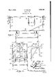
- Figure l is a side elevation of an invalid bed showing my improved hoisting or lifting mechanism applied thereto;
- Figure 2 is an end view thereof, the inoperative position of the hoisting device being indicated in dotted lines;
- Figure' 3 is a fragmentary perspective viewV of one end of my improved hoisting mechanism, showing the operating crank;
- Figure 4 is an enlarged transverse section 12 on the line 4-4 of Figure 1, the adjacent ⁇ parts being shown in elevation and broken away.
- I provide a support or sub-frame A which may be mounted on rollers or the like, and on which the main bed frame B is carried.
- the bed B is preferably supported on the sub-frame A by means of a plurality of springs 1, shown as helical springs. These are interposed between transverse frame members 3 forming part of the sub-frame and transverse members 4 forming part of the bed frame proper, and the springs may be maintained in position by means of bolts Serial No. 558,384.
- he bed B comprises the usual spring bot- Y tom, the head section C of which may be adjustable ⁇ into a more or lessinclined position, as is usual. Y.
- the bed comprises foot and head board 'frames 5 and 6, each being of rectangular shape, and having an upper cross bar or'rail such as 5a.
- the bottom section C may be supported in adjustedposition by means of. a pin c fitting into any one of a series of holes in the head board frame 6.
- Pivotally secured as at 7 and 8 to oneof lthe vertical .membersfof the head and fo'ot board frames 5 and 6 respectively are a pair of inclined arms 9 and 10. These are pivoted to the bed .frames at their lower ends and carry at their upper ends bearing members which may conveniently consist of plumber-s Ts 11 and 12.
- this shaft may conveniently consist of a piece of ordinary-wrought iron pipe, and it will,
- crank 15 is secured to the shaft 13.
- the means for attaching this crank may conveniently consist of an ordinary plumbers elbow 14, into which both the crank and shaft are screwed.
- a cap 14a or the like is preferably screwed to the end of the shaft where it projects through the T 12 in order to secure the partsV together.- It is desirable to provide means .to lock or hold the shaft against rotation, and for this purpose, I have devised the arrangement shown in Figure 4.
- V'As illustrated in this figure the sleeve of the T, such as 11, is provided with a plurality of spaced diametrically opposed pairs of holes 16 and similarly spaced pairs of holes are providedin the shaft 13 where it passes through the T so that these holes may be caused to register.
- the 4shaft may thus be lockedto theT and held against rotation by Y the Ipati ent at inserting through a pair of aligned holes a locking pin such as 17.
- I In order to hoist or lift the patient from the bed when desired, I provide a plurality of slings.
- Each of these preferably consists of a strap or the like 19, having a buckle 9,1 and secured at its ends tothe ends of a rigid cross bar 2O suspended by means of a strap or cord 18 from the shaft 13 around which shaft the strap or cord y18 is adapted-to be wound, as indicated at 18a when the shaft is rotated.
- a strap or cord 18 from the shaft 13 around which shaft the strap or cord y18 is adapted-to be wound, as indicated at 18a when the shaft is rotated.
- the shaft 13 is 'and foot board frames, clude both an arrangement in which the shaft upper frame members, such as a of the head So far as the invention members such as 5a, or whether the vsleeve of the T, such as 11, rests upon the frame member.
- the T itself rest upon the frame member and thus keep the shaft itself out ofV contact therewith, and this vis illustrated in Figure 1.
- a hoisting device comprising a shaft eX- tending between said head and foot board frames and arranged to be supported thereon, a crank secured to said shaft for rotating the same, slings suspended from .said shaft and constructed to be hoisted when the shaft is rotated, and connections between said shaft and bed whereby theformer, when not vinnse, may b-e shifted laterally and downwardly into inoperative position at one side of the bed and supported from the latter in such p0- sition.
- crank secured to said shaft for rotating the same,slings suspended from said shaft and constructed 'to be hoisted when the shaft is rotated, and a pair ofiinclined arms pivoted at their lower ends .one to the head and one to the foot board frame, respectively, and having at theirupper ends bearings in which said shaft is journalied, whereby, when said Ashaft is not in use, said arms, vcarrying the shaft, may be swung yon their pivots laterally t, ,s
- a hoisting device comprising a pair of arms pivotally Vsecured one to the head andY one to the foot board frame respectively, at one side of said frames and carrying bearings at their free ends, a shaft liourna'lled in said bearings andv supported on the upper edges of said frames, slings suspended from said shaft, a crank for turning said shaft to wind up said slings. and means for locking said shaft to hold the slings in any desired elevated position.
Landscapes
- Health & Medical Sciences (AREA)
- Nursing (AREA)
- Life Sciences & Earth Sciences (AREA)
- Animal Behavior & Ethology (AREA)
- General Health & Medical Sciences (AREA)
- Public Health (AREA)
- Veterinary Medicine (AREA)
- Invalid Beds And Related Equipment (AREA)
Description
E. PHILLIPS 1,856,785
INVALID BED May 3, 1932.
Filed Aug. 20, 1931 m/ @mma Patented May 3, 1932 EVERETT PHILLIPS, F LEESBURG, VIRGINIA INVALID BED Application led August 20, 1931.
This invention relates to invalid beds and more particularly to means for liftingv or hoisting the patient.
Numerous devices for this purpose have l5' heretofore been proposed, but mostv of them have proven impractical Vor unsatisfactory in operation.
An object of the present invention is to provide hoisting mechanism which shall be `1 0 exceptionally inexpensive in construction,
Aand simple and effective in operation.
Another object is to provide a hoisting device of this character which may be readily shifted out of the way to an inoperative posi- 16 tion when not required for use. In order that the invention may be readily understood, `reference is had to the accompanying drawings, forming part of this specification, and in which:
Figure l is a side elevation of an invalid bed showing my improved hoisting or lifting mechanism applied thereto; p
Figure 2 is an end view thereof, the inoperative position of the hoisting device being indicated in dotted lines;
Figure' 3 is a fragmentary perspective viewV of one end of my improved hoisting mechanism, showing the operating crank; and
Figure 4 is an enlarged transverse section 12 on the line 4-4 of Figure 1, the adjacent `parts being shown in elevation and broken away.
Referring to the drawings in detail, I have shown a. construction of bed which I prefer to employ, although it will, of course, be understood that my improved hoisting device canbe used in connection with any bed having head and foot boards of the same height. In the preferred arrangement shown in the drawings, Iprovide a support or sub-frame A which may be mounted on rollers or the like, and on which the main bed frame B is carried. The bed B is preferably supported on the sub-frame A by means of a plurality of springs 1, shown as helical springs. These are interposed between transverse frame members 3 forming part of the sub-frame and transverse members 4 forming part of the bed frame proper, and the springs may be maintained in position by means of bolts Serial No. 558,384.
2 extending through the same andthrough the frame members 3 and 4.
'I he bed B comprises the usual spring bot- Y tom, the head section C of which may be adjustable `into a more or lessinclined position, as is usual. Y.
The bed comprises foot and head board 'frames 5 and 6, each being of rectangular shape, and having an upper cross bar or'rail such as 5a. The bottom section C may be supported in adjustedposition by means of. a pin c fitting into any one of a series of holes in the head board frame 6.
Pivotally secured as at 7 and 8 to oneof lthe vertical .membersfof the head and fo'ot board frames 5 and 6 respectively are a pair of inclined arms 9 and 10. These are pivoted to the bed .frames at their lower ends and carry at their upper ends bearing members which may conveniently consist of plumber-s Ts 11 and 12.
Journalled in these bearing Ts and extending horizontally from end to end of the bed 'is a shaft V13. In-practice, it is found that this shaft may conveniently consist of a piece of ordinary-wrought iron pipe, and it will,
of course, be understood that it is of such size as to pass freely through the Ts 11 and At one end, and at a point just beyond the bearing T, such as 11, a crank 15 is secured to the shaft 13. The means for attaching this crank may conveniently consist of an ordinary plumbers elbow 14, into which both the crank and shaft are screwed.
At the other end, a cap 14a or the like is preferably screwed to the end of the shaft where it projects through the T 12 in order to secure the partsV together.- It is desirable to provide means .to lock or hold the shaft against rotation, and for this purpose, I have devised the arrangement shown in Figure 4.
V'As illustrated in this figure,- the sleeve of the T, such as 11, is provided with a plurality of spaced diametrically opposed pairs of holes 16 and similarly spaced pairs of holes are providedin the shaft 13 where it passes through the T so that these holes may be caused to register. The 4shaft may thus be lockedto theT and held against rotation by Y the Ipati ent at inserting through a pair of aligned holes a locking pin such as 17. i In order to hoist or lift the patient from the bed when desired, I provide a plurality of slings. Each of these preferably consists of a strap or the like 19, having a buckle 9,1 and secured at its ends tothe ends of a rigid cross bar 2O suspended by means of a strap or cord 18 from the shaft 13 around which shaft the strap or cord y18 is adapted-to be wound, as indicated at 18a when the shaft is rotated. Two of such slings are illustrated in the drawings, and these will ordinarily be sufficient, but obviously-anydesired number can be employed.
In operation, it will be understood that the straps 19 are placed around and under the proper points and then, upon turning the crank 15, the cords or straps '18 will be wound upon the shaft 13, and the patient will be lifted or hoisted, as
Y required, and may be held -in such elevated position by locking the shaft by means of the locking pin 17.
It will be understood that the weight of the shaft and of the lpatient is Vborne by the point,
fication rand claims', the shaft 13 is 'and foot board frames, clude both an arrangement in which the shaft upper frame members, such as a of the head So far as the invention members such as 5a, or whether the vsleeve of the T, such as 11, rests upon the frame member. However, froma practical standit is preferred that the T itself rest upon the frame member and thus keep the shaft itself out ofV contact therewith, and this vis illustrated in Figure 1.` I wish to ypoint out, however, that where, in the specidescribed as supported on or resting upon thel head it is intended to initself contacts with the frame and an arranga ment i-n which only the sleeve .of the Ts ccnkfacts with the frame.
From a. consideration Vof the manner in "which my improved and simplified hoisting mechanism is constructed, it will be apparent that when it is not desired to use the same, the arms 9 and 10, and with them the shaft 13, may be swung to the left, as viewed in Figure 2, laterally and downwardly into lan inoperative position at the .side of the bed, as shown in dotted lines. lVhen in `this position, it is entirely out ofthe way, and leavesthe space above the bed free `and unobstructed. Vhen wanted for use, the shaft an-d its associated parts can be quickly swung upwardly into position again and will be ready to operate immediately without the necessity for making any adjustments whatsoever or releasing or tightening any screws, clampsor the like.
What I claim is: y
1. The combination with a bed having the 2. The combination with a bed having the vusual yvertical head and foot board frames,
of a hoisting device comprising a shaft eX- tending between said head and foot board frames and arranged to be supported thereon, a crank secured to said shaft for rotating the same, slings suspended from .said shaft and constructed to be hoisted when the shaft is rotated, and connections between said shaft and bed whereby theformer, when not vinnse, may b-e shifted laterally and downwardly into inoperative position at one side of the bed and supported from the latter in such p0- sition. l
8. The combination nwith a bed having the usual vertical head and foot .board frames, of a hoisting device comprising a shaft'extending between said vhead and foot board frames and arranged tobe supported thereon,
a crank secured to said shaft for rotating the same,slings suspended from said shaft and constructed 'to be hoisted when the shaft is rotated, and a pair ofiinclined arms pivoted at their lower ends .one to the head and one to the foot board frame, respectively, and having at theirupper ends bearings in which said shaft is journalied, whereby, when said Ashaft is not in use, said arms, vcarrying the shaft, may be swung yon their pivots laterally t, ,s
and downwardly, into inoperative position.
#1. The combination with a bed having the vusual verticall head and foot board frames,
of a hoisting device comprising a pair of arms pivotally Vsecured one to the head andY one to the foot board frame respectively, at one side of said frames and carrying bearings at their free ends, a shaft liourna'lled in said bearings andv supported on the upper edges of said frames, slings suspended from said shaft, a crank for turning said shaft to wind up said slings. and means for locking said shaft to hold the slings in any desired elevated position. In testimony EVERETT PHILLIPS.
whereof I affix my signature.
Priority Applications (1)
| Application Number | Priority Date | Filing Date | Title |
|---|---|---|---|
| US558384A US1856785A (en) | 1931-08-20 | 1931-08-20 | Invalid bed |
Applications Claiming Priority (1)
| Application Number | Priority Date | Filing Date | Title |
|---|---|---|---|
| US558384A US1856785A (en) | 1931-08-20 | 1931-08-20 | Invalid bed |
Publications (1)
| Publication Number | Publication Date |
|---|---|
| US1856785A true US1856785A (en) | 1932-05-03 |
Family
ID=24229337
Family Applications (1)
| Application Number | Title | Priority Date | Filing Date |
|---|---|---|---|
| US558384A Expired - Lifetime US1856785A (en) | 1931-08-20 | 1931-08-20 | Invalid bed |
Country Status (1)
| Country | Link |
|---|---|
| US (1) | US1856785A (en) |
Cited By (2)
| Publication number | Priority date | Publication date | Assignee | Title |
|---|---|---|---|---|
| US4530122A (en) * | 1982-06-07 | 1985-07-23 | Sanders Ez Mobility Systems | Patient weight reliever apparatus |
| US5031605A (en) * | 1989-10-05 | 1991-07-16 | Michael Mills | Medical gin pole |
-
1931
- 1931-08-20 US US558384A patent/US1856785A/en not_active Expired - Lifetime
Cited By (2)
| Publication number | Priority date | Publication date | Assignee | Title |
|---|---|---|---|---|
| US4530122A (en) * | 1982-06-07 | 1985-07-23 | Sanders Ez Mobility Systems | Patient weight reliever apparatus |
| US5031605A (en) * | 1989-10-05 | 1991-07-16 | Michael Mills | Medical gin pole |
Similar Documents
| Publication | Publication Date | Title |
|---|---|---|
| NO781694L (en) | PERSONAL CEILING DEVICE. | |
| US2057811A (en) | Bed attachment for invalids | |
| US1856785A (en) | Invalid bed | |
| US1487150A (en) | Sling attachment for hospital beds | |
| US1712974A (en) | Scaffold bracket | |
| US1720714A (en) | Derrick | |
| US1558636A (en) | Hoisting apparatus | |
| NO145494B (en) | DEVICE FOR LIFTING A SLEEPING PATIENT | |
| US1301284A (en) | Lifting device. | |
| US2008770A (en) | Attachment for hospital beds | |
| US943003A (en) | Device for handling invalids. | |
| US2350595A (en) | Apparatus for lifting and turning invalids in bed | |
| US2091909A (en) | Attachment for casket lowering devices | |
| US1823771A (en) | Window stage | |
| US1802227A (en) | Car-door hanger | |
| US1052791A (en) | Hoisting apparatus. | |
| US1879848A (en) | Portable transformer and hoist | |
| US1332624A (en) | Stretcher | |
| US484974A (en) | Invalid s adjustable back-rest | |
| US1528545A (en) | Table attachment for beds | |
| US124398A (en) | Isabella wallee | |
| US1601908A (en) | Bed | |
| US1018825A (en) | Mattress-turning apparatus. | |
| US2524314A (en) | Invalid carrier | |
| US1186570A (en) | Quilting-frame. |