US1856776A - Buckle for belts or straps - Google Patents
Buckle for belts or straps Download PDFInfo
- Publication number
- US1856776A US1856776A US514733A US51473331A US1856776A US 1856776 A US1856776 A US 1856776A US 514733 A US514733 A US 514733A US 51473331 A US51473331 A US 51473331A US 1856776 A US1856776 A US 1856776A
- Authority
- US
- United States
- Prior art keywords
- belt
- plate
- latch
- buckle
- plates
- Prior art date
- Legal status (The legal status is an assumption and is not a legal conclusion. Google has not performed a legal analysis and makes no representation as to the accuracy of the status listed.)
- Expired - Lifetime
Links
- 238000010276 construction Methods 0.000 description 5
- 239000010985 leather Substances 0.000 description 2
- 241000733322 Platea Species 0.000 description 1
- 241000287181 Sturnus vulgaris Species 0.000 description 1
- 239000002131 composite material Substances 0.000 description 1
- 239000000463 material Substances 0.000 description 1
- 230000004048 modification Effects 0.000 description 1
- 238000012986 modification Methods 0.000 description 1
- 238000001988 small-angle X-ray diffraction Methods 0.000 description 1
Images
Classifications
-
- A—HUMAN NECESSITIES
- A44—HABERDASHERY; JEWELLERY
- A44B—BUTTONS, PINS, BUCKLES, SLIDE FASTENERS, OR THE LIKE
- A44B11/00—Buckles; Similar fasteners for interconnecting straps or the like, e.g. for safety belts
- A44B11/20—Buckles; Similar fasteners for interconnecting straps or the like, e.g. for safety belts engaging holes or the like in strap
- A44B11/22—Buckle with fixed prong
- A44B11/226—Buckle with fixed prong with cover plate
-
- Y—GENERAL TAGGING OF NEW TECHNOLOGICAL DEVELOPMENTS; GENERAL TAGGING OF CROSS-SECTIONAL TECHNOLOGIES SPANNING OVER SEVERAL SECTIONS OF THE IPC; TECHNICAL SUBJECTS COVERED BY FORMER USPC CROSS-REFERENCE ART COLLECTIONS [XRACs] AND DIGESTS
- Y10—TECHNICAL SUBJECTS COVERED BY FORMER USPC
- Y10T—TECHNICAL SUBJECTS COVERED BY FORMER US CLASSIFICATION
- Y10T24/00—Buckles, buttons, clasps, etc.
- Y10T24/40—Buckles
- Y10T24/4002—Harness
- Y10T24/4028—Penetrating tongue
- Y10T24/4037—Pivoted
- Y10T24/4042—Stud
-
- Y—GENERAL TAGGING OF NEW TECHNOLOGICAL DEVELOPMENTS; GENERAL TAGGING OF CROSS-SECTIONAL TECHNOLOGIES SPANNING OVER SEVERAL SECTIONS OF THE IPC; TECHNICAL SUBJECTS COVERED BY FORMER USPC CROSS-REFERENCE ART COLLECTIONS [XRACs] AND DIGESTS
- Y10—TECHNICAL SUBJECTS COVERED BY FORMER USPC
- Y10T—TECHNICAL SUBJECTS COVERED BY FORMER US CLASSIFICATION
- Y10T24/00—Buckles, buttons, clasps, etc.
- Y10T24/40—Buckles
- Y10T24/4095—Fabric covered
Definitions
- Our present invention relates to buckles, and has for its important object an improvement 1n belt or strap buckles, for any purpose to which these are usually utilized and Where-V in the strains encountered in such buckles are distributed and dispersed over greater areas of the leather or other material of the belt or strap, and preventing tearing thereof or undue stretching.
- the present device is along the same line of construction as that set forth in the copending application of Albertv Meehan, Serial No. 495,625, led Nov. 14th, 1930, for belt buckles, and is an improvement thereover.
- One of the important features vof construction relates to the means provided for removably and independently attaching the buckle to both ends of a belt, the rear or blind end of the belt being substantially semipermanently encased in a box like beltholding structure normally closed, the other or front end of the belt being easily accessible for removal or adjustment thereof.
- Another feature lies in the construction of the latch plate, in which all the strains of the belt, in use, are all taken up and supported by the latch plate, alone, thus creating a unitary straining means which is in a single piece with the strain forces in balance, thus relieving the buckle itself of diverse strains on the various parts thereof.
- Another feature is in the joining ofthe back plate, latch plate and front plate and in which they are all joined into a pivoted structure on a common pivot point, thus making the plural parts of the buckle into a single, unitary structure.
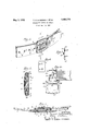
- Fig. 1 is a perspective front view of our device in locking engagement With and as applied to a belt, the belt being fragmentarily shown.
- Fig. 2 is a transverse sectional view taken on the line 2 2, Fig. l, looking in the direction of the arrows.
- Fig. 8 is a longitudinal sectional vieiv taken on the line 3-3, Fig. 1 looking in the direction of the arrows.
- Fig. 4 is a plan vievv of the blind 'end portion of the belt with the frontplate opened, and with the latch and back plates in locked engagement Withsaid blind end.
- Fig. 5 is a side view ofthe latch plate separated and removed from the Vother components of the buckle.
- Fig. 6 is a fragmentaryk end vievT of the rear or blind end portion lof the belt shovve ing the latch engaging slots therein.
- Fig. 1 the device is shown as applied to a belt' comprising a rear or blind end portion 1 and ai front portion 2, the free end of which 3 is provided along its center With a plurality of alined oval straight sided slots 4.
- the device is shown as comprising three separate pieces, the f'ront or cover plate 5, the belt latch plate 6 and the lback plate 7, all of these being curled at the bottom ends so as to hingedly engage around a pintle 8 so that when the buckle is opened the members 5, 6 and Z are angularly divergent from one another to permit the'introduction of both the belt ends l and 2.
- the back plate 7 is merely a e flat plate having an inturned top ledge 9 and an inturned angular-ly formed end ledge l0, these ledges being formed in such a manner as to lit the rear, blind end 1 of the belt and encase the same on the top side and end as in Fig. 4, While the bottom side of the belt as' inA Fig. 2 is held in boxed position by the hinge forming portions 14, 15 and 16 of the coordinating commonly joined front, latch and back plate members. This construction is best noted in Fig. 2 wherein the rear squared end lof the belt is encompassed on its two sides and one end. V
- rlfhe belt portion l1 is further provided with a pair of elongated straight side slots ll'vvhich 4are in' Vvertical alinement With one another as in Fig. 6, and these are so positioned as to come into registry with the blanked up vertically positioned latch lugs 12 which are formed on and extend to the rear ot the latch plate 6 sothat when the squared belt end 1 is in position in the belt encompassing back plate 7 and the pivot latch plate 6 is closed down thereupon, the flat facedlugs 1,2 engage in the apertures 11 and the latch plate A6, having a spring latch ledge 13 on its upper end engages over the inturned edge portion 9 of 'the back plate in a resilient manner and thereby is latched in locked position as show-n in vFigs.
- T he ,detailed hinging structure 'of the three buckle members 5, 6 and 7 to 'the pivot pin 8 is as follows. rlhe back plate 7 has two intermediately located 'curled or formed' fer- 'rules 14, Fig.
- the latch plate 6 has "a single wide centrally located ferrule 15 curled about the pin 8 while the front cover plate 5 has two Aoutside curled errules 16 'curled about the outer yends of the pivot 8, so that all three are freely swingable upon ⁇ the pivot, each one independent of the other so that they may perform their composite functions lree'ot one another but coordinate to actas a ingle belt or strap engaging buckle mein-
- the front plate 5 at the side opposite its hinge portion 16 is provided with a curled spring-like latch 17, which, owing to the lconstruction 'of the front plate, which may be slightly bowed, lends all of its resilience to the permitting 'of the lat'ching member 17 to snap and 'unsna'p love'rthe ycurved latch end 13ot the latchplate Gwhen operated to close as in Fig. 2,'and toopen,
- rlhe latch plate ⁇ 6 in the belt :engaging pfosition as in Fig. 4 has a pair of outwardly :projecting stampedv out horizontally alined belt 'latch lugs 18, thesev being in substantial transverse alinement and project to the front side of the latch plate, as 'indicated in Figs. 3, 4 and 5.
- the rear belt end holding lugs 12, being blanked out of the latch ⁇ plate oppositely tothe lugs 18 and at right angles thereto to form belt'or strap engaging lugs on opposite side of the latch plate and these engage the rear sepiaied 'end of the belt 1.
- any strain subjected to the belt falls upon the opposing lugs 12 and 1-8, and the opposing strains are confined to the latch plate 6 only, and the other back and front plates 7 and 5 have no other duty to perform than merely to coact to enclose the buckle assembly.
- the cover plate may be made wider than the coordinating back belt end structure and may be ornamented to any suitable degree.
- the transverse section Fig. 3 shows the manner in which the belt .ends are in engagement in the structure, the 'box like structure comprising the latch plate 6 and the rear plateY 7 ,being fully shown in this view, and the enclosing function of the front plate 5 also being fully shown.
- Abelt buckle comprising, in combination ywith a belt'member, a back plate,'a 'latch the back plate and another belt, properly perplate interlocking with said back plate, and a front plate, all of said plates being hingedly connected together, means on said front plate for latching with said interlocked back and latch plates and means on said latch plate for holding the ends of said belt.
- a belt buckle of the class described comprising a back plate and a latch plate, said latch plate having opposedly mounted belt and engaging lugs thereon, a cover plate therefor, all of said plates being pivotally connected to a common hinge point and means for latching all said plates to hold saine in closed assembly.
- a belt buckle of the class described coniprising a back plate and a latch plate, said latch plate having opposedly mounted belt end engaging lugs thereon, a cover plate therefor, all of said plates being pivotallyV connected to a common hinge point and means for releasably latching all. said plates together to hold same in closed assembly.
- a belt buckle of the class described comprising a back plate, 4a front plate and an intermediate latch plate all hinged together at one of their ends and having interengaging latching means at their opposite ends whereby the latch plate may engage said back plate and the cover plate will engage the said latch plate and plural lugs on said latch plate projecting towards said back and cover plates.
- a belt buckle of the class described in combination with a belt having apertured ends, comprising a back plate, a front plate and a latch plate all hinged together at one of their ends and having interengaging latching means at their opposite ends whereby the latch plate may engage said back plate and the cover plate will engage the said latch plate and belt aperture engaging lugs on said latch plate projecting both ways from said latch plate and towards said cover and back plates to engage with both the ends of said belt, simultaneously.
- a buckle comprising in combination with a belt, a back plate, swingable latch and iront plates, said plates being pivotally connected with each other at one of their ends, said latch plate having means for holding the ends of the belt, and means whereby the free ends of said plates are separably interlocked with each other.
- a buckle comprising in combination with a belt, a back plate, a swingable latch plate having means thereon for holding the ends of the belt, a flanged front plate, means pivotally connecting said plates together at one of their ends, and means whereby the free ends of said plates are separably interlocked with each other.
- a buckle comprising in combination with a belt, a back platea hingedly movable latch plate, means carried by said latter plate for holding the ends of the belt, a hingedly movable front plate, hinge means connecting said plates together at one of their ends, and a spring constructed flange carried by each- ⁇ plate, whereby the free ends of said plates are separably interlocked with each other, said plates being of progressively increasing width.
- a buckle comprising in combination with a belt having perforated ends, a back plate for engaging one of said ends, a swingable front plate for engaging the other end, an interposed swingable plate, oppositely projecting lugs carried by said latter plate for entering the perforations of said ends to hold the latter, hinge means connecting said plates together at one of their ends, and springable flanges integral with the free ends of said plates whereby the said free ends are separably interlocked with each other, said plates being ⁇ of progressively increasing width.
Landscapes
- Buckles (AREA)
Description
May 3, 1932- T. A, MCDERMOTT ET Al.
BUCKLE FOR BELTS OR STRAPS Filed Feb. 10. 1931 mvENToRs,
18 @977242594 ./er-fna IQ@ Alfieri Magia, l
ATTORNEY.
Patented May 3, 1932 Unirse stares earner orties THOMAS A. MCDERMOTT AND ALBERT MEEHAN, `0F NEW YORK, N. Y.; SAID MCDERMOTT ASSIGNOR TO SAXD MEEHAN BUCKLE FOR BELTS OR STRAPS Application filed February 10, 1931. Serial No. 514,733.
Our present invention relates to buckles, and has for its important object an improvement 1n belt or strap buckles, for any purpose to which these are usually utilized and Where-V in the strains encountered in such buckles are distributed and dispersed over greater areas of the leather or other material of the belt or strap, and preventing tearing thereof or undue stretching.
The present device is along the same line of construction as that set forth in the copending application of Albertv Meehan, Serial No. 495,625, led Nov. 14th, 1930, for belt buckles, and is an improvement thereover.
One of the important features vof construction relates to the means provided for removably and independently attaching the buckle to both ends of a belt, the rear or blind end of the belt being substantially semipermanently encased in a box like beltholding structure normally closed, the other or front end of the belt being easily accessible for removal or adjustment thereof.
Another feature lies in the construction of the latch plate, in which all the strains of the belt, in use, are all taken up and supported by the latch plate, alone, thus creating a unitary straining means which is in a single piece with the strain forces in balance, thus relieving the buckle itself of diverse strains on the various parts thereof.
Another feature is in the joining ofthe back plate, latch plate and front plate and in which they are all joined into a pivoted structure on a common pivot point, thus making the plural parts of the buckle into a single, unitary structure.
Features of arrangement of the latch members on the latch plate, the shape of the eoordinating slots in the belt -ends for better distribution of strains in the leather, and the details of latching the structure to a belt, are
Aall of novel trend, and increase the utility and ease of operation.
Modifications may be made in the structure herein Without departing from the spirit hereof nor the scope of the appended claims.
In the drawings:
Fig. 1 is a perspective front view of our device in locking engagement With and as applied to a belt, the belt being fragmentarily shown. v
Fig. 2 is a transverse sectional view taken on the line 2 2, Fig. l, looking in the direction of the arrows.
Fig. 8 is a longitudinal sectional vieiv taken on the line 3-3, Fig. 1 looking in the direction of the arrows.
Fig. 4 is a plan vievv of the blind 'end portion of the belt with the frontplate opened, and with the latch and back plates in locked engagement Withsaid blind end.
Fig. 5 is a side view ofthe latch plate separated and removed from the Vother components of the buckle; and
Fig. 6 is a fragmentaryk end vievT of the rear or blind end portion lof the belt shovve ing the latch engaging slots therein.
In Fig. 1 the device is shown as applied to a belt' comprising a rear or blind end portion 1 and ai front portion 2, the free end of which 3 is provided along its center With a plurality of alined oval straight sided slots 4.
ln Fig. 2 the device is shown as comprising three separate pieces, the f'ront or cover plate 5, the belt latch plate 6 and the lback plate 7, all of these being curled at the bottom ends so as to hingedly engage around a pintle 8 so that when the buckle is opened the members 5, 6 and Z are angularly divergent from one another to permit the'introduction of both the belt ends l and 2.
To this end the back plate 7 is merely a e flat plate having an inturned top ledge 9 and an inturned angular-ly formed end ledge l0, these ledges being formed in such a manner as to lit the rear, blind end 1 of the belt and encase the same on the top side and end as in Fig. 4, While the bottom side of the belt as' inA Fig. 2 is held in boxed position by the hinge forming portions 14, 15 and 16 of the coordinating commonly joined front, latch and back plate members. This construction is best noted in Fig. 2 wherein the rear squared end lof the belt is encompassed on its two sides and one end. V
rlfhe belt portion l1 is further provided with a pair of elongated straight side slots ll'vvhich 4are in' Vvertical alinement With one another as in Fig. 6, and these are so positioned as to come into registry with the blanked up vertically positioned latch lugs 12 which are formed on and extend to the rear ot the latch plate 6 sothat when the squared belt end 1 is in position in the belt encompassing back plate 7 and the pivot latch plate 6 is closed down thereupon, the flat facedlugs 1,2 engage in the apertures 11 and the latch plate A6, having a spring latch ledge 13 on its upper end engages over the inturned edge portion 9 of 'the back plate in a resilient manner and thereby is latched in locked position as show-n in vFigs. 1 and 2, but best shown in Fig.v 2. As thus engaged the buckle construction isA Al'ockably engaged to the squared rear end of the belt in such a manner that the only loose vmember of the assembly is the 'opened' front plate 5 which,'as shown in Fig.` 4, is swung down wardlyfrom the pivot 8.
T he ,detailed hinging structure 'of the three buckle members 5, 6 and 7 to 'the pivot pin 8 is as follows. rlhe back plate 7 has two intermediately located 'curled or formed' fer- 'rules 14, Fig. 4, which engage around the pivot pin 8, the latch plate 6 has "a single wide centrally located ferrule 15 curled about the pin 8 while the front cover plate 5 has two Aoutside curled errules 16 'curled about the outer yends of the pivot 8, so that all three are freely swingable upon `the pivot, each one independent of the other so that they may perform their composite functions lree'ot one another but coordinate to actas a ingle belt or strap engaging buckle mein- The front plate 5 at the side opposite its hinge portion 16 is provided with a curled spring-like latch 17, which, owing to the lconstruction 'of the front plate, which may be slightly bowed, lends all of its resilience to the permitting 'of the lat'ching member 17 to snap and 'unsna'p love'rthe ycurved latch end 13ot the latchplate Gwhen operated to close as in Fig. 2,'and toopen,
rlhe latch plate`6 in the belt :engaging pfosition as in Fig. 4 has a pair of outwardly :projecting stampedv out horizontally alined belt 'latch lugs 18, thesev being in substantial transverse alinement and project to the front side of the latch plate, as 'indicated in Figs. 3, 4 and 5. The rear belt end holding lugs 12, being blanked out of the latch` plate oppositely tothe lugs 18 and at right angles thereto to form belt'or strap engaging lugs on opposite side of the latch plate and these engage the rear sepiaied 'end of the belt 1.
4 vWhen the cover plate 5 is opened as in Fig. 4 the frontend of the belt 3 with its 'apertures 4 therein, which are spaced equally apart and in valinement, yis then placed over the latch plate with the V'projectinglugs 18 projecting into and lregistering with the plural slots 4 and'thereafter the front plate 5 is snapped thereover, snap latch 17 there on engaging over the latch 13 of latch plate 6, as in Fig. 2, closing the entire assembly and keeping the two belt ends in pertect alinement.
It is obvious that any strain subjected to the belt falls upon the opposing lugs 12 and 1-8, and the opposing strains are confined to the latch plate 6 only, and the other back and front plates 7 and 5 have no other duty to perform than merely to coact to enclose the buckle assembly.
The cover plate may be made wider than the coordinating back belt end structure and may be ornamented to any suitable degree.
In operation 'of the device it is merely necessary to grasp-the loose end 3.0i the belt and pull on it which will unsnap the plate 5 and throw it in the position shown in Fig. 4, whereupon the belt may be removed or it may be adjusted to suit by moving the belt and registering its .slots 4 with the belt lugs 18-18.
The transverse section Fig. 3 shows the manner in which the belt .ends are in engagement in the structure, the 'box like structure comprising the latch plate 6 and the rear plateY 7 ,being fully shown in this view, and the enclosing function of the front plate 5 also being fully shown. l
lt is obvious, asset torth, that owing to the 'fact that there are 'at least two prongs or lugs 12 and 18 in 'engagement with both beltends and that owing to the 'wide :tacespresented by thenformationy of'these lugs and the'elongation of 'thejslots in both :belt ends, that there is a wider distributionjo the strain 'torcesset up in the belt ends and thereby the tendency of the belt to :tear under strainsis jobvi ated, and the strain forces are 'distributed more evenly due to the wide :tacedcontacts between A the lugs 'and the-slotted sides.
l It is also obvious that the'opposing strains of the two belt 'ends rpulling against each other are localized'to the latchplate only and that the longitudinal forces do not affect the back nor front plates.
It is also'obvious that' when 'the rontvplate is removed for adjustment oft the free end 3 ofthe belt that the whole structure remains firmly engaged with 'the rear end ot' the belt 1, Vby reason of 'the engagement ofthe latch and back plates thereto and there is notendency tor the buckle 'to drop ott' or become loose and yetat' the same time, if it is desired to transferthe'buckleto another belt this may be readily done by releasing the catch 13 of the latch plate 6 from Vthe latch portion 9 of we claim is 1. Abelt buckle comprising, in combination ywith a belt'member, a back plate,'a 'latch the back plate and another belt, properly perplate interlocking with said back plate, and a front plate, all of said plates being hingedly connected together, means on said front plate for latching with said interlocked back and latch plates and means on said latch plate for holding the ends of said belt.
2. A belt buckle of the class described comprising a back plate and a latch plate, said latch plate having opposedly mounted belt and engaging lugs thereon, a cover plate therefor, all of said plates being pivotally connected to a common hinge point and means for latching all said plates to hold saine in closed assembly.
3. A belt buckle of the class described coniprising a back plate and a latch plate, said latch plate having opposedly mounted belt end engaging lugs thereon, a cover plate therefor, all of said plates being pivotallyV connected to a common hinge point and means for releasably latching all. said plates together to hold same in closed assembly.
el. A belt buckle of the class described comprising a back plate, 4a front plate and an intermediate latch plate all hinged together at one of their ends and having interengaging latching means at their opposite ends whereby the latch plate may engage said back plate and the cover plate will engage the said latch plate and plural lugs on said latch plate projecting towards said back and cover plates.
5. A belt buckle of the class described, in combination with a belt having apertured ends, comprising a back plate, a front plate and a latch plate all hinged together at one of their ends and having interengaging latching means at their opposite ends whereby the latch plate may engage said back plate and the cover plate will engage the said latch plate and belt aperture engaging lugs on said latch plate projecting both ways from said latch plate and towards said cover and back plates to engage with both the ends of said belt, simultaneously.
6. A buckle comprising in combination with a belt, a back plate, swingable latch and iront plates, said plates being pivotally connected with each other at one of their ends, said latch plate having means for holding the ends of the belt, and means whereby the free ends of said plates are separably interlocked with each other.
7. A buckle comprising in combination with a belt, a back plate, a swingable latch plate having means thereon for holding the ends of the belt, a flanged front plate, means pivotally connecting said plates together at one of their ends, and means whereby the free ends of said plates are separably interlocked with each other.
S. A buckle comprising in combination with a belt, a back platea hingedly movable latch plate, means carried by said latter plate for holding the ends of the belt, a hingedly movable front plate, hinge means connecting said plates together at one of their ends, and a spring constructed flange carried by each-` plate, whereby the free ends of said plates are separably interlocked with each other, said plates being of progressively increasing width.
9. A buckle comprising in combination with a belt having perforated ends, a back plate for engaging one of said ends, a swingable front plate for engaging the other end, an interposed swingable plate, oppositely projecting lugs carried by said latter plate for entering the perforations of said ends to hold the latter, hinge means connecting said plates together at one of their ends, and springable flanges integral with the free ends of said plates whereby the said free ends are separably interlocked with each other, said plates being` of progressively increasing width.
Signed at New York city, in the county of New York and State of New York, this 7th day of February A. D. 1931.
THOMAS A. MCDERMOTT. ALBERT MEEHAN.
Priority Applications (1)
| Application Number | Priority Date | Filing Date | Title |
|---|---|---|---|
| US514733A US1856776A (en) | 1931-02-10 | 1931-02-10 | Buckle for belts or straps |
Applications Claiming Priority (1)
| Application Number | Priority Date | Filing Date | Title |
|---|---|---|---|
| US514733A US1856776A (en) | 1931-02-10 | 1931-02-10 | Buckle for belts or straps |
Publications (1)
| Publication Number | Publication Date |
|---|---|
| US1856776A true US1856776A (en) | 1932-05-03 |
Family
ID=24048453
Family Applications (1)
| Application Number | Title | Priority Date | Filing Date |
|---|---|---|---|
| US514733A Expired - Lifetime US1856776A (en) | 1931-02-10 | 1931-02-10 | Buckle for belts or straps |
Country Status (1)
| Country | Link |
|---|---|
| US (1) | US1856776A (en) |
Cited By (9)
| Publication number | Priority date | Publication date | Assignee | Title |
|---|---|---|---|---|
| US2891254A (en) * | 1957-07-01 | 1959-06-23 | Essex Metal Products Company | Buckle construction with decorative panel |
| US3209423A (en) * | 1963-01-28 | 1965-10-05 | Andre Brauchi | Locking device for straps |
| US3251108A (en) * | 1964-09-17 | 1966-05-17 | Marlene M Harrison | Buckle for adjustable shoulder strap |
| FR2423181A1 (en) * | 1978-04-20 | 1979-11-16 | Spillmann Sa C R | CLASP FOR SOFT BRACELET |
| FR2478968A1 (en) * | 1980-03-28 | 1981-10-02 | Gautier Ets Georges | Belt buckle fixed to one extremity of belt - by stud passing through hole in belt held by pivoting cover |
| US5896626A (en) * | 1996-09-05 | 1999-04-27 | Betula Schuh Gmbh | Clip clasp for securing a strap |
| US7181808B1 (en) * | 2006-05-31 | 2007-02-27 | Denzal Wayne Van Winkle | Buckle or clasp |
| USD640448S1 (en) * | 2009-07-22 | 2011-06-28 | Regius Vestio, LLC. | Belt loop |
| US11882891B1 (en) * | 2020-04-14 | 2024-01-30 | Blue Force Gear, Inc. | Belt |
-
1931
- 1931-02-10 US US514733A patent/US1856776A/en not_active Expired - Lifetime
Cited By (9)
| Publication number | Priority date | Publication date | Assignee | Title |
|---|---|---|---|---|
| US2891254A (en) * | 1957-07-01 | 1959-06-23 | Essex Metal Products Company | Buckle construction with decorative panel |
| US3209423A (en) * | 1963-01-28 | 1965-10-05 | Andre Brauchi | Locking device for straps |
| US3251108A (en) * | 1964-09-17 | 1966-05-17 | Marlene M Harrison | Buckle for adjustable shoulder strap |
| FR2423181A1 (en) * | 1978-04-20 | 1979-11-16 | Spillmann Sa C R | CLASP FOR SOFT BRACELET |
| FR2478968A1 (en) * | 1980-03-28 | 1981-10-02 | Gautier Ets Georges | Belt buckle fixed to one extremity of belt - by stud passing through hole in belt held by pivoting cover |
| US5896626A (en) * | 1996-09-05 | 1999-04-27 | Betula Schuh Gmbh | Clip clasp for securing a strap |
| US7181808B1 (en) * | 2006-05-31 | 2007-02-27 | Denzal Wayne Van Winkle | Buckle or clasp |
| USD640448S1 (en) * | 2009-07-22 | 2011-06-28 | Regius Vestio, LLC. | Belt loop |
| US11882891B1 (en) * | 2020-04-14 | 2024-01-30 | Blue Force Gear, Inc. | Belt |
Similar Documents
| Publication | Publication Date | Title |
|---|---|---|
| US1856776A (en) | Buckle for belts or straps | |
| US842498A (en) | Garment-fastener. | |
| US1591295A (en) | Clasp for bracelets | |
| US686690A (en) | Buckle. | |
| US2156647A (en) | Belt buckle | |
| US1791037A (en) | And george d | |
| US270296A (en) | Theodore w | |
| US2225890A (en) | Combined locking and clipping device for articles of jewelry | |
| US1856775A (en) | Belt buckle | |
| US2767452A (en) | Clasp | |
| US1852188A (en) | Brooch or clasp | |
| US1574832A (en) | Key retainer | |
| US2004206A (en) | Extendible clasp or connecting device for straps, bands, and bracelets | |
| US1232531A (en) | Trousers band and fastener. | |
| US1779633A (en) | Belt buckle | |
| US1233932A (en) | Back-band buckle, &c. | |
| US175310A (en) | Improvement in duplex reversible buckles | |
| US1374949A (en) | Camera-case | |
| US1591294A (en) | Clasp for bracelets | |
| US1729793A (en) | Clasp | |
| US1456130A (en) | Belt buckle | |
| US1493684A (en) | Flexible fastener for belts | |
| US2797462A (en) | Indicia mounting means for belt buckles and the like | |
| US1340302A (en) | Buckle | |
| US155813A (en) | Improvement in buckles |