US1856775A - Belt buckle - Google Patents
Belt buckle Download PDFInfo
- Publication number
- US1856775A US1856775A US495625A US49562530A US1856775A US 1856775 A US1856775 A US 1856775A US 495625 A US495625 A US 495625A US 49562530 A US49562530 A US 49562530A US 1856775 A US1856775 A US 1856775A
- Authority
- US
- United States
- Prior art keywords
- belt
- buckle
- plate
- pins
- inner end
- Prior art date
- Legal status (The legal status is an assumption and is not a legal conclusion. Google has not performed a legal analysis and makes no representation as to the accuracy of the status listed.)
- Expired - Lifetime
Links
Images
Classifications
-
- A—HUMAN NECESSITIES
- A44—HABERDASHERY; JEWELLERY
- A44B—BUTTONS, PINS, BUCKLES, SLIDE FASTENERS, OR THE LIKE
- A44B11/00—Buckles; Similar fasteners for interconnecting straps or the like, e.g. for safety belts
- A44B11/20—Buckles; Similar fasteners for interconnecting straps or the like, e.g. for safety belts engaging holes or the like in strap
- A44B11/22—Buckle with fixed prong
- A44B11/226—Buckle with fixed prong with cover plate
-
- Y—GENERAL TAGGING OF NEW TECHNOLOGICAL DEVELOPMENTS; GENERAL TAGGING OF CROSS-SECTIONAL TECHNOLOGIES SPANNING OVER SEVERAL SECTIONS OF THE IPC; TECHNICAL SUBJECTS COVERED BY FORMER USPC CROSS-REFERENCE ART COLLECTIONS [XRACs] AND DIGESTS
- Y10—TECHNICAL SUBJECTS COVERED BY FORMER USPC
- Y10T—TECHNICAL SUBJECTS COVERED BY FORMER US CLASSIFICATION
- Y10T24/00—Buckles, buttons, clasps, etc.
- Y10T24/40—Buckles
- Y10T24/4002—Harness
- Y10T24/4028—Penetrating tongue
- Y10T24/4037—Pivoted
- Y10T24/4042—Stud
Definitions
- This invention relates to improvements in fastening devices for use in connection with garment supporting belts, straps or girdles and is particularly directed to a novel construction in interchangeable belt buckles.
- a principal objectof the invention is in the provision of a buckle of the above type in which the inner end of a belt may be readily attached and detached from the buckle structure when desired, so that the same buckle may be employed with different belts.
- Another important object of the invention being to provide removable means whereby the inner end of a belt may be detachably secured to'the improved buckle in a manner to avoid separation of the belt and buckle when not in use.
- An inventive feature is present in the buckle construction whereby a tandem lock is provided, and further, whereby longitudmal stresses exerted by the belt when in use, may be distributed equally to the sides of the buckle structure, so that thin material may be employed therefor, if desired.
- FIG. 1 Further features of the invention consist in the provision of a rear stamped member, preferably of sheet metal, providing a channel seat for the inner end of the belt, and a front stampd member'formed with outward- '30 ly drawn pockets to receive the outer ends of preferably a pair of lock pins riveted to the, rear member; the ends of the belt being punched with spaced holes to receive the pins.
- the members being hingedly connected i5 along the longitudinal center of the'bottom of the buckle and having yielding interlocking connection at the top of the buckle; spring clip means being also provided for detachably securing the buckle to the inner end of 46 the belt, by engagement with grooves in the cross pins.
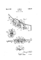
- Fig. 1 is aperspective view of the buckle attached w to a belt and in the locked position.
- Fig. 2 is a longitudinal sectional view of the assembly of buckle and belt, the line of lsfiection being best indicated as at 2-2 of rig. 3.
- Fig. 3 is a vertical cross sectional elevation taken substantially on the line 3-3 of Fig. 1 and looking as the arrow points, and
- Fig. 4 is a detail face view of a plate clip device employed to detachably lock the inner end of the belt in its seat.
- My improved interchangeable belt buckle 10 may be formed of two main parts preferably of sheet metal so that they may be made by stamping and shaping for economy.
- These main elements of the box buckle comprise a rear member 11 of general channel form, and a front member 12, also of general channel form; the lower edge portions of these members 11 and 12, being bent inwardly and curled into alined sleeves 13, to receive a pintle pin 14, thereby to hinge the members together. It will benoted that this hinging point is centrally of the bottom 15 or angularly disposed flange of the buckle, and runs longitudinally thereof for purposes hereinafter set forth.
- the rear member-11 has aor portion 16 which is bent outwardly at a right angle to provide a top plate or flange portion 17 which at about its longitudinal center, is crimped inwardly to form an inwardly directed spacing or retaining rib 18, and theedge of said top plate 17 is appropriatelycurled to form a longitudinal spring bead or catch 19, with which a curled spring head or catch 20'provided on the upper edge of the front member 12, interlocks to yieldingly hold the members closed.
- This inner end 27 of the belt 28 is additionally heldagainst outward movement from its seated position within the box-like lnner member 11 of thebuckle, by the longiplane back plate tudinal rib 18, of the top plate 17 and also by the alined hinging sleeves 13 on the bottom of the buckle; that portion of the rear member 11 back of the ribs 18 and the hinging sleeves 13 forming a seat 29, for the said inner end of said belt.
- the front member 12 is constituted largely by a plane front plate 12a, which is formed with stamped out pockets or sockets 30 of a width that their side walls 31 engage the sides of said pins, and these sides of the pockets are adapted to take longitudinal belt stresses exerted on the outer portions of the pins 22, the rear member 11, taking half of the pulling stresses at the base of said pins to balance the strains.
- the inner end 27 of the belt is provided with two or more holes 41 spaced to correspond to the spacing of the lock pins 22 so that when attaching the belt 28 to the buckle 10, this inner end is held with the holes 41 over the pins 22, and forced inwardly to its seat 29, in the rear member 11, past the rib 18 and the sleeves 13 of the hinge joint, which rib and sleeves also serve to hold the said inner end in its seat after which the clip plate 26, is forced in over the pins until the spring tongues 25 spring into the grooves 23, in said pins which serve as a detachable means for holding the said end in place, after which the outer end 27a, of the belt may be adjusted with two of the holes 40, over the lock pins 22, after which the front member 12 of the buckle may be swung upward and snapped into interlocking engagement with the rear member through the spring beads 19 and 20 as will be obvious.
- a belt buckle an inner part and an outer part hinged together, and having respective interlocking spring portions, means extending through the inner end and outer end of a belt at two points for locking the belt to the buckle, said points being spaced and in the axis of pull of the belt, and means for distributing the belt stresses equally to the inner and outer parts of the buckle.
- a detachable belt buckle comprising a rear wall having an angularly disposed flange and a springable flange parallel with said first flange, a swingable front wall, means hingedly connecting said latter wall and said first flange, spring means integral with said front wall to cooperate with said second flange for holding said front wall in a closed position to releasably engage one end of a belt, which latter is provided with an aperture, said front wall having therein a pocket, means projecting from said rear Wall for passing into said pocket through said aperture and through the other end of a belt for holding said ends, said second end being also provided with an aperture, and a rib carried by said springable flange for detachably holding said second end in the open position of the buckle.
- a rear part having a rectangular seat, a longitudinal inwardly directed rib, a spring bead on one edge and spaced curled sleeves on the other edge, a front part having outwardly punched pockets, curled sleeves on one edge and a spring bead on the other edge, a pintle pin engaging said sleeves to form a hinge joint and lock-pins riveted to the rear part and extending into the pockets of the front part of said buckle.
- a belt buckle an inner part having a seat to receive the inner end of a belt; lockpins having grooves therein, an outer part hinged to the inner part and having pockets therein, a clip plate on said pins and interlocking with said grooves to hold the inner end of a belt in its seat, said lock pins extending from the inner part, through holes in said inner end of the belt, the clip plate, through holes in the outer end of saidbelt and into said pockets in engagement with the side walls thereof for taking part of the belt tension strains, and spring means for interlocking the parts of the buckle.
- a buckle for belt terminals which latter have registering openings therein, said buckle including a box-like section having a plain rear wall, a front section movable between open and closed positions, hinges connecting said sections, said second section having a pocket therein, and, rigid means projecting from the front surface of said wall for engaging in said pocket and in openings as aforesaid, whereby to hold said terminals against relative movement when said second section is in the closed position.
- a buckle for belt terminals which latter are provided with registering openings, said buckle including a flat rear wall having outwardly turned flanges for engaging the edges of belt terminals, a relatively movable flat front wall having pockets therein, hinges connecting said latter wall and one of said flanges, and rigid means projecting from said rear wall and engageable in openings as aforesaid and in said pocketswhereby to hold said terminals against movement when said walls are disposed in parallel relation.
- a buckle for a belt having terminals, which latter are provided with registering openings said buckle including a rear plate having angularly disposed flanges for engaging belt edges, a front plate movable between open and closed positions andhaving a pocket therein, means hingedly connecting one portion of said latter plate with one of said flanges, a catch on another portion of said latter plate for securing the same to the other flange in closed relation, and rigid means carried by said first plate and engageable in said pocket and in registering openings of said terminals, whereby to secure said terminals against movement while the buckle is closed.
- a buckle for releasably engaging belt terminals the latter being provided with openings, said buckle including a flat rear plate and having right angularly disposed spring flanges, a rib on one of said flanges for engaging an edgeof one belt terminal, hinge elements carried by the other flange for engaging the opposite edge of the last mentioned terminal, a relatively movable fiat front plate having hinge elements disposed in cooperation with said first elements, said latter plate having a pocket therein and being swingable inwardly into parallel relation with said first plate for releasably engaging the other belt terminal, and rigid means carried by said first plate and engageable in said pocket and in opening of said terminals, said second terminal being releasable on swinging said front plate outwardly, and said first terminal being releasable on movement of said spring flanges.
Landscapes
- Automotive Seat Belt Assembly (AREA)
Description
- May'3, 1932. MEEHA 1,856,775
BELT BUCKLE Filefl Nov. 14, 1930 INVENTOR ATTORNEY Patented May 3, 1932 ALBERT MEEHAN, OF NEW YORK, N. Y.
BELT BUCKLE I Application filed November 14, 1930. Serial No. 495,625.
This invention relates to improvements in fastening devices for use in connection with garment supporting belts, straps or girdles and is particularly directed to a novel construction in interchangeable belt buckles.
A principal objectof the invention is in the provision of a buckle of the above type in which the inner end of a belt may be readily attached and detached from the buckle structure when desired, so that the same buckle may be employed with different belts.
Another important object of the invention being to provide removable means whereby the inner end of a belt may be detachably secured to'the improved buckle in a manner to avoid separation of the belt and buckle when not in use.
. An inventive feature is present in the buckle construction whereby a tandem lock is provided, and further, whereby longitudmal stresses exerted by the belt when in use, may be distributed equally to the sides of the buckle structure, so that thin material may be employed therefor, if desired.
Further features of the invention consist in the provision of a rear stamped member, preferably of sheet metal, providing a channel seat for the inner end of the belt, and a front stampd member'formed with outward- '30 ly drawn pockets to receive the outer ends of preferably a pair of lock pins riveted to the, rear member; the ends of the belt being punched with spaced holes to receive the pins.
The members being hingedly connected i5 along the longitudinal center of the'bottom of the buckle and having yielding interlocking connection at the top of the buckle; spring clip means being also provided for detachably securing the buckle to the inner end of 46 the belt, by engagement with grooves in the cross pins. A
In the drawings presented herewith, there is illustrated an embodiment now thought to be the best form of my buckle, but it will be understood that changes and refinements may be made in the construction within the scope of the invention claimed. In the several views of the drawings, Fig. 1 is aperspective view of the buckle attached w to a belt and in the locked position.
Fig. 2 is a longitudinal sectional view of the assembly of buckle and belt, the line of lsfiection being best indicated as at 2-2 of rig. 3.
1 Fig. 3 is a vertical cross sectional elevation taken substantially on the line 3-3 of Fig. 1 and looking as the arrow points, and
Fig. 4 is a detail face view of a plate clip device employed to detachably lock the inner end of the belt in its seat.
My improved interchangeable belt buckle 10 may be formed of two main parts preferably of sheet metal so that they may be made by stamping and shaping for economy.
These main elements of the box buckle comprise a rear member 11 of general channel form, and a front member 12, also of general channel form; the lower edge portions of these members 11 and 12, being bent inwardly and curled into alined sleeves 13, to receive a pintle pin 14, thereby to hinge the members together. It will benoted that this hinging point is centrally of the bottom 15 or angularly disposed flange of the buckle, and runs longitudinally thereof for purposes hereinafter set forth.
The rear member-11, has aor portion 16 which is bent outwardly at a right angle to provide a top plate or flange portion 17 which at about its longitudinal center, is crimped inwardly to form an inwardly directed spacing or retaining rib 18, and theedge of said top plate 17 is appropriatelycurled to form a longitudinal spring bead or catch 19, with which a curled spring head or catch 20'provided on the upper edge of the front member 12, interlocks to yieldingly hold the members closed.
Riveted as at 21, 21, to the back plate and on the longitudinal axis thereof, are inwardly directed lock or cross pins 22, preferably formed with annular grooves 23 with which the inner edges 24 of spring tongues 25, provided on: a slitted clip plate 26, engage. This plate functions to retain the inner end 27, of the belt 28,'against outward movement on the pins 22. This inner end 27 of the belt 28, is additionally heldagainst outward movement from its seated position within the box-like lnner member 11 of thebuckle, by the longiplane back plate tudinal rib 18, of the top plate 17 and also by the alined hinging sleeves 13 on the bottom of the buckle; that portion of the rear member 11 back of the ribs 18 and the hinging sleeves 13 forming a seat 29, for the said inner end of said belt.
The front member 12, is constituted largely by a plane front plate 12a, which is formed with stamped out pockets or sockets 30 of a width that their side walls 31 engage the sides of said pins, and these sides of the pockets are adapted to take longitudinal belt stresses exerted on the outer portions of the pins 22, the rear member 11, taking half of the pulling stresses at the base of said pins to balance the strains.
The inner end 27 of the belt is provided with two or more holes 41 spaced to correspond to the spacing of the lock pins 22 so that when attaching the belt 28 to the buckle 10, this inner end is held with the holes 41 over the pins 22, and forced inwardly to its seat 29, in the rear member 11, past the rib 18 and the sleeves 13 of the hinge joint, which rib and sleeves also serve to hold the said inner end in its seat after which the clip plate 26, is forced in over the pins until the spring tongues 25 spring into the grooves 23, in said pins which serve as a detachable means for holding the said end in place, after which the outer end 27a, of the belt may be adjusted with two of the holes 40, over the lock pins 22, after which the front member 12 of the buckle may be swung upward and snapped into interlocking engagement with the rear member through the spring beads 19 and 20 as will be obvious.
It will be noted that by placing the hinge point centrally of the bottom of the buckle body, the front member or part when released will swing outwardly downwardly and clear of the lock-pins and the front end of the belt to permit its easy removal from said ins.
What I claim is:
1. In a belt buckle, an inner part and an outer part hinged together, and having respective interlocking spring portions, means extending through the inner end and outer end of a belt at two points for locking the belt to the buckle, said points being spaced and in the axis of pull of the belt, and means for distributing the belt stresses equally to the inner and outer parts of the buckle.
2. A detachable belt buckle comprising a rear wall having an angularly disposed flange and a springable flange parallel with said first flange, a swingable front wall, means hingedly connecting said latter wall and said first flange, spring means integral with said front wall to cooperate with said second flange for holding said front wall in a closed position to releasably engage one end of a belt, which latter is provided with an aperture, said front wall having therein a pocket, means projecting from said rear Wall for passing into said pocket through said aperture and through the other end of a belt for holding said ends, said second end being also provided with an aperture, and a rib carried by said springable flange for detachably holding said second end in the open position of the buckle.
3. In an interchangeable belt buckle, a rear part having a rectangular seat, a longitudinal inwardly directed rib, a spring bead on one edge and spaced curled sleeves on the other edge, a front part having outwardly punched pockets, curled sleeves on one edge and a spring bead on the other edge, a pintle pin engaging said sleeves to form a hinge joint and lock-pins riveted to the rear part and extending into the pockets of the front part of said buckle.
4.. In a belt buckle, an inner part having a seat to receive the inner end of a belt; lockpins having grooves therein, an outer part hinged to the inner part and having pockets therein, a clip plate on said pins and interlocking with said grooves to hold the inner end of a belt in its seat, said lock pins extending from the inner part, through holes in said inner end of the belt, the clip plate, through holes in the outer end of saidbelt and into said pockets in engagement with the side walls thereof for taking part of the belt tension strains, and spring means for interlocking the parts of the buckle.
5. A buckle for belt terminals which latter have registering openings therein, said buckle including a box-like section having a plain rear wall, a front section movable between open and closed positions, hinges connecting said sections, said second section having a pocket therein, and, rigid means projecting from the front surface of said wall for engaging in said pocket and in openings as aforesaid, whereby to hold said terminals against relative movement when said second section is in the closed position.
6. A buckle for belt terminals, which latter are provided with registering openings, said buckle including a flat rear wall having outwardly turned flanges for engaging the edges of belt terminals, a relatively movable flat front wall having pockets therein, hinges connecting said latter wall and one of said flanges, and rigid means projecting from said rear wall and engageable in openings as aforesaid and in said pocketswhereby to hold said terminals against movement when said walls are disposed in parallel relation.
7. A buckle for a belt having terminals, which latter are provided with registering openings, said buckle including a rear plate having angularly disposed flanges for engaging belt edges, a front plate movable between open and closed positions andhaving a pocket therein, means hingedly connecting one portion of said latter plate with one of said flanges, a catch on another portion of said latter plate for securing the same to the other flange in closed relation, and rigid means carried by said first plate and engageable in said pocket and in registering openings of said terminals, whereby to secure said terminals against movement while the buckle is closed.
8. A buckle for releasably engaging belt terminals, the latter being provided with openings, said buckle including a flat rear plate and having right angularly disposed spring flanges, a rib on one of said flanges for engaging an edgeof one belt terminal, hinge elements carried by the other flange for engaging the opposite edge of the last mentioned terminal, a relatively movable fiat front plate having hinge elements disposed in cooperation with said first elements, said latter plate having a pocket therein and being swingable inwardly into parallel relation with said first plate for releasably engaging the other belt terminal, and rigid means carried by said first plate and engageable in said pocket and in opening of said terminals, said second terminal being releasable on swinging said front plate outwardly, and said first terminal being releasable on movement of said spring flanges.
Signed at New York, in the county of New York and State of New York, this 13th day of November, A. D. 1930.
ALBERT MEEHAN.
Priority Applications (1)
| Application Number | Priority Date | Filing Date | Title |
|---|---|---|---|
| US495625A US1856775A (en) | 1930-11-14 | 1930-11-14 | Belt buckle |
Applications Claiming Priority (1)
| Application Number | Priority Date | Filing Date | Title |
|---|---|---|---|
| US495625A US1856775A (en) | 1930-11-14 | 1930-11-14 | Belt buckle |
Publications (1)
| Publication Number | Publication Date |
|---|---|
| US1856775A true US1856775A (en) | 1932-05-03 |
Family
ID=23969347
Family Applications (1)
| Application Number | Title | Priority Date | Filing Date |
|---|---|---|---|
| US495625A Expired - Lifetime US1856775A (en) | 1930-11-14 | 1930-11-14 | Belt buckle |
Country Status (1)
| Country | Link |
|---|---|
| US (1) | US1856775A (en) |
Cited By (6)
| Publication number | Priority date | Publication date | Assignee | Title |
|---|---|---|---|---|
| US3181221A (en) * | 1963-09-04 | 1965-05-04 | Jeffrey Allan Ind Inc | Seat belt buckle |
| US5896626A (en) * | 1996-09-05 | 1999-04-27 | Betula Schuh Gmbh | Clip clasp for securing a strap |
| US20030140461A1 (en) * | 2000-06-15 | 2003-07-31 | Peter Wilcock | Buckle |
| US7181808B1 (en) * | 2006-05-31 | 2007-02-27 | Denzal Wayne Van Winkle | Buckle or clasp |
| US7325424B1 (en) * | 2006-11-01 | 2008-02-05 | Wolf Iii William B | Saddle locking device and method |
| USD1069644S1 (en) * | 2023-08-03 | 2025-04-08 | Hermes Sellier (Société par Actions Simplifiée) | Buckle |
-
1930
- 1930-11-14 US US495625A patent/US1856775A/en not_active Expired - Lifetime
Cited By (6)
| Publication number | Priority date | Publication date | Assignee | Title |
|---|---|---|---|---|
| US3181221A (en) * | 1963-09-04 | 1965-05-04 | Jeffrey Allan Ind Inc | Seat belt buckle |
| US5896626A (en) * | 1996-09-05 | 1999-04-27 | Betula Schuh Gmbh | Clip clasp for securing a strap |
| US20030140461A1 (en) * | 2000-06-15 | 2003-07-31 | Peter Wilcock | Buckle |
| US7181808B1 (en) * | 2006-05-31 | 2007-02-27 | Denzal Wayne Van Winkle | Buckle or clasp |
| US7325424B1 (en) * | 2006-11-01 | 2008-02-05 | Wolf Iii William B | Saddle locking device and method |
| USD1069644S1 (en) * | 2023-08-03 | 2025-04-08 | Hermes Sellier (Société par Actions Simplifiée) | Buckle |
Similar Documents
| Publication | Publication Date | Title |
|---|---|---|
| US1856775A (en) | Belt buckle | |
| US1598719A (en) | Bag handle and handle attachment | |
| US1856776A (en) | Buckle for belts or straps | |
| US1931707A (en) | Hand bag fastener | |
| US2177506A (en) | Handbag latch | |
| US1477692A (en) | Trunk bolt | |
| US3080562A (en) | Loose leaf binder | |
| US2156647A (en) | Belt buckle | |
| US1455545A (en) | Belt buckle | |
| US1550904A (en) | Belt buckle | |
| US1741603A (en) | Traveling-case frame | |
| US1495471A (en) | Belt buckle | |
| US1696586A (en) | Fastener slide | |
| US2004406A (en) | Buckle | |
| US1706183A (en) | Key case | |
| US2349926A (en) | Lady's handbag | |
| US1782665A (en) | Clasp for pocketbooks and the like | |
| US2017410A (en) | Bag frame | |
| US2106142A (en) | Handbag fastener structure | |
| US1374949A (en) | Camera-case | |
| US2634483A (en) | Belt buckle | |
| US1764547A (en) | Knickbe | |
| US1516514A (en) | Latch fastener for bags | |
| US1931511A (en) | Frame | |
| US1609080A (en) | Fastener |