US1853897A - Tank for locomotive tenders - Google Patents
Tank for locomotive tenders Download PDFInfo
- Publication number
- US1853897A US1853897A US521770A US52177031A US1853897A US 1853897 A US1853897 A US 1853897A US 521770 A US521770 A US 521770A US 52177031 A US52177031 A US 52177031A US 1853897 A US1853897 A US 1853897A
- Authority
- US
- United States
- Prior art keywords
- walls
- compartment
- conveyor
- chamber
- tank
- Prior art date
- Legal status (The legal status is an assumption and is not a legal conclusion. Google has not performed a legal analysis and makes no representation as to the accuracy of the status listed.)
- Expired - Lifetime
Links
- 230000003137 locomotive effect Effects 0.000 title description 18
- 239000000446 fuel Substances 0.000 description 22
- 238000005266 casting Methods 0.000 description 12
- XLYOFNOQVPJJNP-UHFFFAOYSA-N water Substances O XLYOFNOQVPJJNP-UHFFFAOYSA-N 0.000 description 6
- 238000010276 construction Methods 0.000 description 2
- 239000004449 solid propellant Substances 0.000 description 2
- 239000002253 acid Substances 0.000 description 1
- 238000006243 chemical reaction Methods 0.000 description 1
- 239000003245 coal Substances 0.000 description 1
- 238000005520 cutting process Methods 0.000 description 1
- 230000006866 deterioration Effects 0.000 description 1
- JEIPFZHSYJVQDO-UHFFFAOYSA-N iron(III) oxide Inorganic materials O=[Fe]O[Fe]=O JEIPFZHSYJVQDO-UHFFFAOYSA-N 0.000 description 1
- 238000012423 maintenance Methods 0.000 description 1
- 238000004519 manufacturing process Methods 0.000 description 1
- 239000002184 metal Substances 0.000 description 1
- 238000000034 method Methods 0.000 description 1
- 238000012986 modification Methods 0.000 description 1
- 230000004048 modification Effects 0.000 description 1
- 238000005728 strengthening Methods 0.000 description 1
Images

Classifications
-
- B—PERFORMING OPERATIONS; TRANSPORTING
- B61—RAILWAYS
- B61C—LOCOMOTIVES; MOTOR RAILCARS
- B61C17/00—Arrangement or disposition of parts; Details or accessories not otherwise provided for; Use of control gear and control systems
- B61C17/02—Bunkers; Tanks; Tenders; Water or fuel pick-up or scoop apparatus; Water or fuel supply fittings
Definitions
- the present invention relates to improve 7 thereof which is herein exemplified, a locoments in the tanks of locomotive tenders.v
- the object of thisinvention is to provide a tender tank having a fuel chamber disposed therein, formed as an integral casting, which structure will avoid the aforesaid undesirable characteristics of the fabricated cha n: bers and materially reduce both the cost of manufacture and maintenance of the tender tank.
- Another object of the invention is to provide such a chamber having a fuel conveyor compartment also .formed integrally therewith.
- a further object is to provide such a chamber having a conveyor trough and conveyor shaft bearing also formed integrally with the fuel chamber.
- the invention is illustrated in the accome panying drawings, in which v 1 t Figure 1 is a partial side view of the locomotive tender showing the invention applied thereto; Fig. 2 is a front view of the same; Fig. 3 is an enlarged longitudinal section of the fuel chamber on the line III-III'of,Fig.
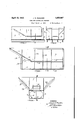
- Fig. 4 at the right half is a front end view of Fig. 3, and at the left half is 'a section on the line IV-IV ofFig. 3;
- Fig. 5 is a half plan view ofv the same;
- Fig. 6 is a longitudinal section on the line VI-VI of F ig. 7, showing a modified form of the fuel,
- Fig. 7 at the right side is a front end view, and .at the left side i'safsem tion on the. line VIIVII, ofiFig. -6.-,
- the specific; embodiment motive tender tank indicated generally by the numeral 1
- the tank embodies the usual water section 3, formed by side plates 4,..whi'ch are turned at their front ends to form'front plates 5, bottom plates 6, and the usual rear and roof plates (not shown), allof which plates are suitablyv attached together'in the usual manner.
- Thefuel chamber is formed as an integral one piece casting, indicated generally by the tal Walls 11 are disposed, a space being left between their inner edges for the passage of fuel therethrough to the rectangular convey- ,or' compartment formed by the walls 9, 10
- an inclined wall 12 extends fromvthe top ofthe tender tank, inwardly downward to the rear end of the walls 11, the walls8, 11 and 12, forming a hoppercompartment for thefuel chamber.
- a vertical wall 13 extends downward from theisaid wall 12 to the rear end 7 ofthe bottom wall 10, closing the conveyor compartment,
- An opening 14 isprovided in the Wall 12 between its connections to the walls 111 and 13, andjan opening 15*is, pro vided at the rear end of the bottom Wall 10,
- Strengthen ing ribs are provided at suitable points of jointure of the walls as indicated at 16, 17 and 18, and the inclined walls 8 are reinforced by ribs 26.
- the inner edges of the horizontal walls 11 are formed with fianges19 adapted to engage cover members (not shown), in such places as may be desired.
- FIG. 6 and 7 a modified form of the conveyor compartment is illustrated.
- the said compartment is closed by a wall 20 providing a completely enclosed chamber to the rear ofthe same and walls 21 are extended downwardly and inwardly from the inner edges of the walls 11 meeting at their lower ends at the center of. the tank and forming a conveyor trough beneath the open passageway 22.
- Bracing legs 23 are formed between the bottom wall 27 and the bottOm oftlie trough.
- the rear wall 20 closes the end of the trough and forms a walled chamber to the rear of the same.
- the said wall 20 is formed with a bearing 24 adapted to support the rear end of a conveyor shaft, longitudinally disposed in the trough and having a screw formed thereon, as indicated in the dotted lines (Fig.
- Suitable gears 25 are connected to the shaft for'operating the same, within the said chamber to the rear of the wall 20, said chamber providing a housing for such gearing.
- the bottom wall 27 of this structure is formed with openings 28 for the purpose of reducing the weight of the casting.
- a locomotive tender tank having a fuel chamber formed as a separate unit disposed within the same, said chamber comprising an integral structure.
- a locomotive tender tank having a fuel chamber formed as a separate unit disposed within the same, said chamber comprising an integral casting having downwardly and inwardly inclined side and rear walls.
- a locomotive tender tank having a fuel chamber formed as a separate unit disposed within the same said chamber comprising an integral casting having downwardly and inwardly inclined side and rear walls forming a hopper, and an oblong compartment extending longitudinally thereof below said hopper providing a conveyor compartment.
- a locomotive tender tank having a fuel chamber formed as a separate unit disposed within the same, said chamber comprising an integral casting having downwardly and inwardly inclined side and rear walls and horizontal bottom walls forming a hopper compartment, and vertical rear and side walls extending downwardly from .said inclined walls and a horizontal bottom wall for said vertical walls forming an oblong conveyor compartment longitudinally extending beneath the hopper compartment.
- a locomotive tender tank having a fuel chamber formed as a separate unit disposed within the same, said chamber comprising an integral casting having downwardly and inwardly inclined side and rear walls and horizontalbottom wallsforming a hopper compartment, and vertical rear and side walls extending downwardly from said inclined walls and a horizontal bottom wall for said vertical walls forming an oblong conveyor compartment longitudinally of the hopper compartment, said rear inclined wall of the hopper compartment being provided with a covered opening above the conveyor compartment to permit access thereto.
- a locomotive tender tank having a fuel chamber formed as a separate unit disposed within the same, said chamber comprising an integral casting having downwardly and inwardly inclined side and rear walls and horizontal bottom wallsforming a hopper compartment, and vertical rear and side walls extending downwardly from said inclined walls, and a horizontal bottom wall for said vertical walls forming an oblong conveyor compartment longitudinally extending beneath the hopper compartment, said bottom wall of the conveyor compartment being provided with a covered opening to permit access thereto.
- a locomotive tender tank having a fuel chamber formed as a separate unit disposed within the same, said chamber comprising an integral casting having downwardly and inwardly inclined side and rear walls and horizontal bottom walls forming a hopper compartment, and vertical rear and side walls extending downwardly from said in-' clined walls and a horizontal bottom wall for said vertical walls forming an oblong conveyor compartment longitudinally extending beneath the 'hopper compartment, said rear inclined wall of the hopper compartment and saidbottom wall of the conveyor compartment being provided with covered openings permitting access to said conveyor compartment.
- Alocomotive tender tank having a fuel chamber formed as a separate unit disposed within the same, saidchamber comprising an integral'casting having downwardly and inwardly inclined side and rear walls and horizontal bottom wallsforming a hoppercompartment, vertical side and rear walls extending downwardly from said inclined walls of I the hopper compartment and a bottom Wall forming a conveyor compartment, said bot- I tom walls of the hopper compartment having a longitudinal open space therebetween, and a conveyor trough formed on said horizontal walls beneath the said longitudinal space 9.
- a locomotive tender tank having a fuel 7 chamber formed as a separate unit disposed within the same, said chamber comprising an integral casting having downwardly and inwardly inclined side and rear walls and horitending downwardly from said inclined walls of the hopper compartment and a bottom wall for said vertical walls forming a conveyor compartment, said horizontal bottom walls of the hopper compartment having a longitudinal open space therebetween, a conveyor trally disposed solid fuel compartment and i outer water compartments, one on each side of the fuel compartment, said fuel and water I compartments being separated" by a separately formed unit comprising an integrally cast structure having walls and means rigid-j 1y holding the said walls in spaced relation, each of said, walls being formed of a lower vertical section and an upper section extend- 7 ing fromthe upper edge of the lower sectio upwardly and outwardly.
- Alocomotive tender tank having a fuel chamber formed as a separateunit disposed within the same, said chamber comprising an integral casting having downwardly and inwardly inclined side and rear walls andhorizontal bottom walls forming a hopper come partment, vertical side and rear walls extending downwardly from said inclined walls of the hopper compartment and a bottom wall for said vertical walls forming a conveyor compartment said bottom walls of the hopper compartment having a longitudinal open space therebetween, a conveyor trough formed on said'horizontal walls beneath the said longitudinal space, and a wall at the rear of said trough extending from the bottom walls of the hopper compartment to the bottom wall of the conveyor compartment, said rear wall being provided with a bearing for supporting a conveyor shaft.
- a structure for dividing a locomotive tender tank into a water compartment anda fuel compartment comprising a separately formed integrally cast unit having a plurality of walls forming a hopper compartment and aplurality of walls forming a conveyor compartment beneath said hopper compartment.
- a locomotive tender comprising a water compartment and a solidfuel compartment, said compartments being divided by walls comprised in a separately formed onepiece unit comprising an integrally cast structure having retaining walls for the fuel compartment and the top and side walls of the water compartment, a conveyor trough formed at the bottom of the unit, and a walled compartment to the. rear of said trough adapted for housing the gearing for said conveyor.
- a locomotive tender comprisinga cen-
Landscapes
- Engineering & Computer Science (AREA)
- Automation & Control Theory (AREA)
- Transportation (AREA)
- Mechanical Engineering (AREA)
- Cooling, Air Intake And Gas Exhaust, And Fuel Tank Arrangements In Propulsion Units (AREA)
Description
April 12, 1932.
J. R. FOULDE R TANK FOR LOCOMOTIVE TENDERS Filed March 11, 1931 2 Sheets-Sheet l -FIG.I:-
INVENTOR jbmes R fbu/de/ FIGS.-
A RNEY April 12, 1932. J. R. F OULDER v TANK FOR LOCOMOTIVE TENDERS 2 Sheets-Sheet 2 Filed March 11, 1951 FIG. 5.
""III FIGS.-
The present invention relates to improve 7 thereof which is herein exemplified, a locoments in the tanks of locomotive tenders.v
Heretofore, in locomotive practice, the fuel chambers of locomotive tender tanks have been fabricated or built up of metal plates riveted or welded together in their positions in the tank. Due to the acid formed by the afiects of the elements on the coal, such plates have been subjected to rapid deterioration from rust and other chemical reactions. The cost of cutting and fitting the plates and riveting and bolting thesame-has been substantial and replacement or repair of the plates has involved great expense.
The object of thisinvention is to provide a tender tank having a fuel chamber disposed therein, formed as an integral casting, which structure will avoid the aforesaid undesirable characteristics of the fabricated cha n: bers and materially reduce both the cost of manufacture and maintenance of the tender tank. Another object of the invention is to provide such a chamber having a fuel conveyor compartment also .formed integrally therewith. And, a further object is to provide such a chamber having a conveyor trough and conveyor shaft bearing also formed integrally with the fuel chamber. The invention is illustrated in the accome panying drawings, in which v 1 t Figure 1 is a partial side view of the locomotive tender showing the invention applied thereto; Fig. 2 is a front view of the same; Fig. 3 is an enlarged longitudinal section of the fuel chamber on the line III-III'of,Fig.
4; Fig. 4: at the right half is a front end view of Fig. 3, and at the left half is 'a section on the line IV-IV ofFig. 3; Fig. 5 is a half plan view ofv the same; Fig. 6 isa longitudinal section on the line VI-VI of F ig. 7, showing a modified form of the fuel,
chamber; and Fig. 7 at the right side is a front end view, and .at the left side i'safsem tion on the. line VIIVII, ofiFig. -6.-,
In the. practice of the invention, referring descriptively to, the specific; embodiment motive tender tank, indicated generally by the numeral 1, is supported on the longitudinal beams 2 of the tender frame and is connected thereto in the usual manner. The tank embodies the usual water section 3, formed by side plates 4,..whi'ch are turned at their front ends to form'front plates 5, bottom plates 6, and the usual rear and roof plates (not shown), allof which plates are suitablyv attached together'in the usual manner. 1 1
Thefuel chamber is formed as an integral one piece casting, indicated generally by the tal Walls 11 are disposed, a space being left between their inner edges for the passage of fuel therethrough to the rectangular convey- ,or' compartment formed by the walls 9, 10
and 11.
At the rear of the fuel chamber, an inclined wall 12 extends fromvthe top ofthe tender tank, inwardly downward to the rear end of the walls 11, the walls8, 11 and 12, forming a hoppercompartment for thefuel chamber.
'Spaced to the rear of the connection of walls lland 12, a vertical wall 13 extends downward from theisaid wall 12 to the rear end 7 ofthe bottom wall 10, closing the conveyor compartment, An opening 14 isprovided in the Wall 12 between its connections to the walls 111 and 13, andjan opening 15*is, pro vided at the rear end of the bottom Wall 10,
the openings 'aifordingaccess to the conveyor compartment and being provided with suitv able cover plates (not shown) Strengthen ing ribs are provided at suitable points of jointure of the walls as indicated at 16, 17 and 18, and the inclined walls 8 are reinforced by ribs 26. The inner edges of the horizontal walls 11 are formed with fianges19 adapted to engage cover members (not shown), in such places as may be desired.
In Figures 6 and 7, a modified form of the conveyor compartment is illustrated. The said compartment is closed by a wall 20 providing a completely enclosed chamber to the rear ofthe same and walls 21 are extended downwardly and inwardly from the inner edges of the walls 11 meeting at their lower ends at the center of. the tank and forming a conveyor trough beneath the open passageway 22. Bracing legs 23 are formed between the bottom wall 27 and the bottOm oftlie trough. The rear wall 20 closes the end of the trough and forms a walled chamber to the rear of the same. The said wall 20 is formed with a bearing 24 adapted to support the rear end of a conveyor shaft, longitudinally disposed in the trough and having a screw formed thereon, as indicated in the dotted lines (Fig. 6). Suitable gears 25 are connected to the shaft for'operating the same, within the said chamber to the rear of the wall 20, said chamber providing a housing for such gearing. The bottom wall 27 of this structure is formed with openings 28 for the purpose of reducing the weight of the casting.
Vlhile there has, hereinbefore, been clescribed and illustrated, preferred forms of construction of the invention, it will be obvious that many and various changes in procedure, form, arrangement, and construction of parts may be resorted to and that this invention, therefore, is not limited to the particular embodiment disclosed but includes all and any such changes and modifications as come within the spirit and scope of the invention as described in the appended claims.
The invention claimed and desired to be secured by Letters Patent is:
1. A locomotive tender tank having a fuel chamber formed as a separate unit disposed within the same, said chamber comprising an integral structure.
2. A locomotive tender tank having a fuel chamber formed as a separate unit disposed within the same, said chamber comprising an integral casting having downwardly and inwardly inclined side and rear walls.
8. A locomotive tender tank having a fuel chamber formed as a separate unit disposed within the same said chamber comprising an integral casting having downwardly and inwardly inclined side and rear walls forming a hopper, and an oblong compartment extending longitudinally thereof below said hopper providing a conveyor compartment.
4. A locomotive tender tank having a fuel chamber formed as a separate unit disposed within the same, said chamber comprising an integral casting having downwardly and inwardly inclined side and rear walls and horizontal bottom walls forming a hopper compartment, and vertical rear and side walls extending downwardly from .said inclined walls and a horizontal bottom wall for said vertical walls forming an oblong conveyor compartment longitudinally extending beneath the hopper compartment.
5. A locomotive tender tank having a fuel chamber formed as a separate unit disposed within the same, said chamber comprising an integral casting having downwardly and inwardly inclined side and rear walls and horizontalbottom wallsforming a hopper compartment, and vertical rear and side walls extending downwardly from said inclined walls and a horizontal bottom wall for said vertical walls forming an oblong conveyor compartment longitudinally of the hopper compartment, said rear inclined wall of the hopper compartment being provided with a covered opening above the conveyor compartment to permit access thereto.
6. A locomotive tender tank having a fuel chamber formed as a separate unit disposed within the same, said chamber comprising an integral casting having downwardly and inwardly inclined side and rear walls and horizontal bottom wallsforming a hopper compartment, and vertical rear and side walls extending downwardly from said inclined walls, and a horizontal bottom wall for said vertical walls forming an oblong conveyor compartment longitudinally extending beneath the hopper compartment, said bottom wall of the conveyor compartment being provided with a covered opening to permit access thereto.
7 A locomotive tender tank having a fuel chamber formed as a separate unit disposed within the same, said chamber comprising an integral casting having downwardly and inwardly inclined side and rear walls and horizontal bottom walls forming a hopper compartment, and vertical rear and side walls extending downwardly from said in-' clined walls and a horizontal bottom wall for said vertical walls forming an oblong conveyor compartment longitudinally extending beneath the 'hopper compartment, said rear inclined wall of the hopper compartment and saidbottom wall of the conveyor compartment being provided with covered openings permitting access to said conveyor compartment.
8.. Alocomotive tender tank having a fuel chamber formed as a separate unit disposed within the same, saidchamber comprising an integral'casting having downwardly and inwardly inclined side and rear walls and horizontal bottom wallsforming a hoppercompartment, vertical side and rear walls extending downwardly from said inclined walls of I the hopper compartment and a bottom Wall forming a conveyor compartment, said bot- I tom walls of the hopper compartment having a longitudinal open space therebetween, and a conveyor trough formed on said horizontal walls beneath the said longitudinal space 9. A locomotive tender tank having a fuel 7 chamber formed as a separate unit disposed within the same, said chamber comprising an integral casting having downwardly and inwardly inclined side and rear walls and horitending downwardly from said inclined walls of the hopper compartment and a bottom wall for said vertical walls forming a conveyor compartment, said horizontal bottom walls of the hopper compartment having a longitudinal open space therebetween, a conveyor trally disposed solid fuel compartment and i outer water compartments, one on each side of the fuel compartment, said fuel and water I compartments being separated" by a separately formed unit comprising an integrally cast structure having walls and means rigid-j 1y holding the said walls in spaced relation, each of said, walls being formed of a lower vertical section and an upper section extend- 7 ing fromthe upper edge of the lower sectio upwardly and outwardly.
JAMES R. FOULDER.
trough formed on said horizontal walls ben'eath the said longitudinal space, and a wall at the rear of said trough extending from the bottom walls of the hopper compartment to the bottom wall of the conveyor compartment.
10. Alocomotive tender tank having a fuel chamber formed as a separateunit disposed within the same, said chamber comprising an integral casting having downwardly and inwardly inclined side and rear walls andhorizontal bottom walls forming a hopper come partment, vertical side and rear walls extending downwardly from said inclined walls of the hopper compartment and a bottom wall for said vertical walls forming a conveyor compartment said bottom walls of the hopper compartment having a longitudinal open space therebetween, a conveyor trough formed on said'horizontal walls beneath the said longitudinal space, and a wall at the rear of said trough extending from the bottom walls of the hopper compartment to the bottom wall of the conveyor compartment, said rear wall being provided with a bearing for supporting a conveyor shaft.
' 11. A structure for dividing a locomotive tender tank into a water compartment anda fuel compartment, said structure comprising a separately formed integrally cast unit having a plurality of walls forming a hopper compartment and aplurality of walls forming a conveyor compartment beneath said hopper compartment.
12. A locomotive tender comprising a water compartment and a solidfuel compartment, said compartments being divided by walls comprised in a separately formed onepiece unit comprising an integrally cast structure having retaining walls for the fuel compartment and the top and side walls of the water compartment, a conveyor trough formed at the bottom of the unit, and a walled compartment to the. rear of said trough adapted for housing the gearing for said conveyor.
13. A locomotive tender comprisinga cen-
Priority Applications (1)
| Application Number | Priority Date | Filing Date | Title |
|---|---|---|---|
| US521770A US1853897A (en) | 1931-03-11 | 1931-03-11 | Tank for locomotive tenders |
Applications Claiming Priority (1)
| Application Number | Priority Date | Filing Date | Title |
|---|---|---|---|
| US521770A US1853897A (en) | 1931-03-11 | 1931-03-11 | Tank for locomotive tenders |
Publications (1)
| Publication Number | Publication Date |
|---|---|
| US1853897A true US1853897A (en) | 1932-04-12 |
Family
ID=24078078
Family Applications (1)
| Application Number | Title | Priority Date | Filing Date |
|---|---|---|---|
| US521770A Expired - Lifetime US1853897A (en) | 1931-03-11 | 1931-03-11 | Tank for locomotive tenders |
Country Status (1)
| Country | Link |
|---|---|
| US (1) | US1853897A (en) |
-
1931
- 1931-03-11 US US521770A patent/US1853897A/en not_active Expired - Lifetime
Similar Documents
| Publication | Publication Date | Title |
|---|---|---|
| US2222280A (en) | Load discharging car construction | |
| US1853897A (en) | Tank for locomotive tenders | |
| US1422133A (en) | Grain car | |
| US2753815A (en) | Framing structure for a discharge outlet | |
| US1629282A (en) | Underfeed stoker | |
| US1969337A (en) | Locomotive tender | |
| DE690955C (en) | Air-cooled condensation system for turbine locomotives | |
| US1577817A (en) | Freight-car construction | |
| DE926982C (en) | Grate | |
| US1769287A (en) | chase | |
| US1535961A (en) | Furnace stoker | |
| DE547574C (en) | Heater | |
| US1329101A (en) | Dumping-body for trucks | |
| US1397686A (en) | Convertible-car construction | |
| US1346025A (en) | Automatic stock-feeder | |
| US431052A (en) | Locomotive-tender | |
| US1027852A (en) | Locomotive-tender. | |
| US1239558A (en) | Combined stock and gondola car. | |
| US1243868A (en) | Furnace. | |
| US1635239A (en) | Locomotive ash pan | |
| US1731102A (en) | Tender | |
| US2119535A (en) | Locomotive body | |
| US781699A (en) | Tender for locomotives, &c. | |
| US228933A (en) | Feancis eiebee | |
| US1662760A (en) | Hopper door |