US1853846A - Terminal puller - Google Patents
Terminal puller Download PDFInfo
- Publication number
- US1853846A US1853846A US503435A US50343530A US1853846A US 1853846 A US1853846 A US 1853846A US 503435 A US503435 A US 503435A US 50343530 A US50343530 A US 50343530A US 1853846 A US1853846 A US 1853846A
- Authority
- US
- United States
- Prior art keywords
- handles
- jaws
- terminal
- plunger
- tool
- Prior art date
- Legal status (The legal status is an assumption and is not a legal conclusion. Google has not performed a legal analysis and makes no representation as to the accuracy of the status listed.)
- Expired - Lifetime
Links
Images
Classifications
-
- B—PERFORMING OPERATIONS; TRANSPORTING
- B25—HAND TOOLS; PORTABLE POWER-DRIVEN TOOLS; MANIPULATORS
- B25B—TOOLS OR BENCH DEVICES NOT OTHERWISE PROVIDED FOR, FOR FASTENING, CONNECTING, DISENGAGING OR HOLDING
- B25B27/00—Hand tools, specially adapted for fitting together or separating parts or objects whether or not involving some deformation, not otherwise provided for
- B25B27/0035—Hand tools, specially adapted for fitting together or separating parts or objects whether or not involving some deformation, not otherwise provided for for motor-vehicles
- B25B27/005—Hand tools, specially adapted for fitting together or separating parts or objects whether or not involving some deformation, not otherwise provided for for motor-vehicles for pulling off battery terminals
-
- Y—GENERAL TAGGING OF NEW TECHNOLOGICAL DEVELOPMENTS; GENERAL TAGGING OF CROSS-SECTIONAL TECHNOLOGIES SPANNING OVER SEVERAL SECTIONS OF THE IPC; TECHNICAL SUBJECTS COVERED BY FORMER USPC CROSS-REFERENCE ART COLLECTIONS [XRACs] AND DIGESTS
- Y10—TECHNICAL SUBJECTS COVERED BY FORMER USPC
- Y10T—TECHNICAL SUBJECTS COVERED BY FORMER US CLASSIFICATION
- Y10T29/00—Metal working
- Y10T29/53—Means to assemble or disassemble
- Y10T29/53796—Puller or pusher means, contained force multiplying operator
- Y10T29/53804—Battery post and terminal
Definitions
- llt is, therefore, the principal object of my invention to provide a tool which is free from the objections just noted, being capable of use on 'any'terminaliregardless ofhow itis clamped .on the; "post, and being operable with two handles that can be grasped in one hand to pull 0H the' terminal quickly land easily in one operation, namely, thatof pressing the handles together.
- Another vobj ect of myinvention is to providea thoroughly practical and serviceable tool of this kind of light andyetstrong construction and one which can be produced and sold at reasonably low cost.
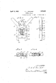
- Fig.A Q' is a side view of Fig. 1; l
- Figs. 3 vand 4 are sections takenfonthe lines 3 3 anda-4; of Fig. 1', looking in the directionsvindicated by the arrows;
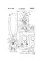
- F ig. 5 is a view lsimilar to Fig'.”1 but partly in section and showing the tool with the aws gripping a terminal on a vbatterypost and Aabout to pull the terminal olf
- Fig. 6 is a plan view of Fig. 5 showing-the jaws in section on'the line 6 6, and
- Fig. 7 is a'view similarito Fig. 5 but 'showing the plunger of the tool advanced by:reason l' of the Iclosing Vof the handles fsorasto- ⁇ pull olf the terminal, this view showingk the handles full length.
- Y i i
- the tool of my invention has a pair of jaws 16 suitably serrated, as at 17, to grip the terminal from opposite sides and arranged to be closed and tightened on the terminal by the bringing together of a pair of handles 18.
- a plunger 19 is moved outwardly between the jaws and brought to bear on the top of the post.
- the handles are actually channel-shaped the full length thereof, as indicated in Fig. 7, and it is simply by cutting away of the connecting web between the two side flanges that the lower Aends of the handles are bifurcated, as is thought will be clear.
- This channel-shaped construction makes the tool that much lighter and easier to handle and it will soon appear how the channel-shaped cross-section is further taken advantage of.
- the handles are. in the form ofbell-crank levers, the lower ends 21 extending outwardly at aniangle with respect thereto.
- Pins 23 are passedthrough the side flanges of the handle spaced inwardly and upwardly from the pins 22, as permitted by the bellcrank form,and these pins provide mountings for rollers 24.
- the latter are disposed between the side flanges of the handles and their function will soon appear.
- the pins project from opposite sides of the handles through upwardly converging slots 25 provided in frame plates 26 fastened, as by means of screws 27, onto opposite sides of a substantially triangular shaped cam 28, the said screws being entered into the base portion of the triangle with the apex portion of said triangle reaching upwardly between the rollers 24.
- a spacer 29 is disposed between the plates 26 at the opposite end thereof from the cam and screws 30 serve to fasten the same in place and hold the plates firmly in the predetermined desired spaced relation.
- the slots 25, previously mentioned, are disposed at such angles that the pins 23 are free to move therein as the rollers 24 ride up on the opposite sides of the cam 28.
- the rollers 24 constitute the fulcrums for the levers 18 with reference to the opposite sides of the cam 28 and the slots 25 permit these rollers to remain in contact with the cam when the same is forced out from between the rollers from the posit-ion shown in Fig. 5 to that shown in Fig. 7.
- a yoke 31 interconnects the jaws 16, the same having its opopsite ends forked, as indicated at 32, for reception of the jaws therein, and the jaws being pivoted thereto, as indicated at 33.
- the pivots 33 are intermediate the ends of the jaws 16 so that the jaws are arranged to be brought together by a toggle action in the closing of the handles 18. It is, of course, evident upon inspection of Fig. 7 that there is considerable leverage exerted by reason of the length of the handles 18 as against the close spacing of the pivots 22 and 23 and further by reason of the distance between the pivots 22 and 23 as against the shorter distance between the pivots 33 and theV serrated ends 17 of the jaws 16. It is, therefore, possible with comparatively light hand pressure in the grasping of the handles to take a good hold on the terminal 10 with the jaws 16 for the removal of the terminal from the post 9.
- This tool is not intended to be used simply to exert a direct pull by hand on the terminal, as should be evident from some of the foregoing statements, but is so designed that the plunger 19, previously referred to, is ar ranged to bring pressure to bear on the post 9 in the pressing together of the handles 18 as the workman closes his grasp thereon, whereby to exert a pull on the terminal coincident with'the gripping thereof by the jaws 16.
- rlhe plunger 19 is simply a pin formed suitably integral with or secured to the cam 28 and extending through a hole 34 provided in a horizontal web portion 35 of t-he yoke 31, the said plunger extending downwardly from the cam between the jaws 16 and being arranged in the closing of the handles to be forced outwardly by reason of the cam 28, as is thought to be evident from y a comparison of F igs. 5 and 7.
- a coiled compression spring 36 fits about the plunger 19 between the cam 28 and the web and serves normally to urge the cam 28 upwardly as far as it will go between the rollers 24, the upward movement being, of course, limited by the pins 23 coming to the lower ends of the slots 25, see Fig. 1.
- the plunger 19 is, of course, retracted at the *same i time by this f'springf action sinceit movesfwith the cam.
- vAtool of the class described comprising, Vin combination, afframe 1nember,afpairv of handles slidably pivotally mounted Von the v frame member for swinging movement. of the free ends thereof towardvand away fromeach other, said levers having angular portionsiat their pivoted ends reaching outwardlyfrom the frame member, apair of work :gripping awslpivotally ⁇ connected at the ends thereof remote from their gripping ends to theends of the angular portions of said handlesfa' ⁇ member extending crosswise between the'l means operated by the'handles for moving said frame member outwardly by cam'actionV in the movement of the free ends of the handles toward each other.
- a tool of the class described comprising a frame member, a pair of handles sli-dab-ly pivoted near their one end on opposite sides 'of said frame member to permitV swinging to advance the outer end ofthe plunger between the gripping ends' of the jawspandV movement 4of the free endsrtoward and away from each other, a pair of work gripping jaws having the ends thereof remote from the gripping, ends pivoted to the handles in vspaced relationv to their pivots on vrtheframe member, a yoke member extending crosswise betweenv the-jaws andpivoted to thelatter intermediate their ends whereby the aws are actuated by the handles by toggle action,
- a tool as set forth in claim 3 including a coiled compression spring litting about the plunger between the frame member and yoke member and serving normally to hold theV yoke member in a predetermined spaced relation to the frame member with the plunger disposed in retracted position relative to the jaws.
- a tool ofthe class described comprising a frame, a pair of handles slidably pivotally f mounted thereon and arranged to be opened and closed, a pair of gripping jaws pivoted relative to one another and arranged to be closed by closing the handles, a plunger movable outwardly in a median plane between the aws a cam for movin said lunrrer the same having converging opposite side faces, the said handles being disposed on the frame so as to fulcrum near their ends on said camV faces whereby to exert a pinching action on 0* -the cam for moving said plunger outwardly relative to the jaws with a force proportionate to the hand pressure exerted on the handles, and toggle operating connections between the ends of said handles and said jaws.
- a tool of the class described comprising a pair of handles arranged to be opened and closed, a pair of gripping jaws arranged to be closed by closing the handles, a plunger movable outwardly in a median plane between the jaws, a frame member carrying said plunger, said handles having sliding pivotal connections near their ends with said member to permit movement of said plunger, toggle connections between said jaws and the ends of said handles, and cam means for moving said frame member and the' plunger with it relative to the handles and jaws in the closing of said handles.
- a tool of the class described comprising in combination a pair of gripping jaws, a pair of handles for operating the same, a plunger disposed for outward movement between the jaws, a frame member whereon said handles are slidably pivotally mounted, a cam on said frame member for moving said plunger, said cam being disposed between the handles so that they fulcrum with respect to opposite sides thereof and transmit pressure Athereto in proportion tothe pressure applied to the handles and thence t0 the jaws, the sides of said cam being formed rearwardly converging so that a forward thrust is communicated thereto and to the plunger when the handles apply pressure to the Vopposite sides of the cam as stated, and said frame member having a pair of guides provided thereon for the sliding movement of the pivots for said handles in predetermined directions, said guides also converging rearwardly similarly as the sides of the cam.
- a tool of the class described comprising in combination a pair of gripping jaws, a pair of handles for operating the same, a plunger disposed for outward movement between the jaws, a frame member whereon said handles are slidably pivotally mounted, and a cam for moving said plunger, said cam being disposed between the handles so that they fulcrum with respect to opposite sides thereof and transmit pressure thereto in proportion to the pressure applied to the handles and thence to the jaws, the sides of said cam being formed rearwardly converging so that a forward thrust is communicated thereto and to the plunger when the handles apply pressure to the opposite sides of the cam as stated.
- a tool of the class described comprising a frame member, a pair of handles pivoted near their one end on opposite sides of the frame member for swinging movement of the free ends toward and away from each other, a pair of work gripping jaws, a yoke member extending crosswise between the jaws and pivoted to the latter intermediate their ends, the jaws Vbeing pivoted to the handles in spaced relationtotheir pivots on the frame member'for operation by the handles by toggle action, a lplunger reciprocable in a hole provided in the yoke member and extensible between the gripping ends of the jaws, the frame member having slots thereon to provide for movement of the pivots for said handles, a cam on the plunger having rearwardly converging side faces, and means on the handles at their pivotal connections with the frame member having bearing contactwith the cam faces, whereby outward movement is arranged to be comwith'the frame member.
- rollers mounted on said handles there being cross-pins on said handles providing mountings .for'said rollers, theends of said j. pins mabeing entered in theA slots in the frame mem# ber for pivotal ,Y connection :of the handles ing a coiled compression spring fitting about Atheiplunger between the cam and yoke mem ber and serving normally to. holdthe yoke member in a predetermined 'spaced' relation to the cam with the plunger disposed in re- ⁇ tracted position relativer/to: the jaws.
- a tool of the class described comprising a pair of handles arranged to be openedand closed, a pair of gripping jaws arranged .to be lclosed by closing the-handles, a frame member, said handles having sliding pivotal yconnections near their ends with said frame member, toggle connections between said jaws and the ends of said handles for closing the jawsfin the closing of the handles, 'a plunger movable outwardly in a median l-plane between the jaws, andcam means operable by the handles for'moving the plunger outwardly relativeto the jaws in the slidingy of the handles on the frame member.
- a ⁇ tool of the class 4,described comprising,l in combination, a pair of handles arranged to be opened and closed whereby to open and vclose gripping jaws 1 associated therewith, a plunger guidedyfor movement outwardly in a median plane between the jaws, and a cam for moving said plunger, said camV being disposed betweenr the handles so Athat'thelatter bear on oppositeY sides 'thereof and transmit pressure thereto in therapplication of pressure to the handlesinthef closing thereof, the sides ,offsaid camv being formed rearwardly converging so that a forward thrust is communicated thereto and to the plunger in the closing of the hand-les;
- Altool of the classv described comprisf*ing,fin combination, a central'member having a Vplunger projecting lforwardly therefrom, a cross-member through which the ⁇ outer'end ofsaid plunger projects, a pair of gripping jaws pivoted intermediate theiry ends to the opposite ends of the cross-mem ber, and apair of handlesjfor operating saidY jaws pivoted at their forward ends to theY rear rends of saidjaws and pivot-ed near their forward ends on opposite sides of said central member, said central member having rearwardly converging slots provided there- ⁇ in and said handlesv being slidably pivotally mounted therein, whereby to permit forward movement of the plunger vwith the central ""member in the closing of the handles.
- a battery terminal 'puller comprising apair of related' handles having jaws to grip a terminal from the sides, said jaws being arrangedvto be closed on the terminal by a predetermined movement ofthe handles rela, tive to one another, va push member to engage the top of the battery post. and means shifting'fits point of reaction for operating the. ⁇ push member by the handles'under a pressure varying. proportionately tov that applied to the jaws. 4
- a battery terminal puller comprising al pairiof related handles havingjaWs to gripy a terminalfrom the sides.A 'said vjaws being arranged to be closed on the terminal bv; a v predetermined movement "of the handles rela-l tive to: one another.Y a push membermovable l Voutwardly to' engage the top ⁇ ofthe battery post, andrmeans comprising a shifting ful- ⁇ crum providing an operating connection between'said handles and said push member# Y lfor givingv movement tov the push memberv while the jaws are held closed on the terminal b v the handles.
- a pulling and pushing tool comprising a pair of related handles having pulling jaws for gripping a piece of work therebetween, said jaws being dependent for their closing pressure upon the closing pressure applied to the handles, and means for simultaneously exerting a pull on said jaws, comprising a pusher to apply pressure to an element of the work, and means comprising a shifting point of reaction for operating said pusher by said handles with a force Varying proportionately to the Closing pressure applied to the jaws.
- a pulling and pushing tool comprising a pair of related handles having gripping jaws arranged to be losed on a piece of work therebetween under hand pressure applied to the handles, a pusher movable outwardly to apply pressure to an element of the work, and a cam action operating connection between the handles andthe pusher Comprising a shifting fulcrum for said handles, whereby the pusher is adapted to exert a pressure varying proportionately to the closing pressure applied to the jaws by the handles.
- a pulling and pushing tool comprising a pair of holding aws, a pair of handles for Closing and opening the jaws whereby to grip a piece of work therebetween, a push member for applying pressure to an element of the work, and means comprising a shifting fulcrum for the handles to move the push member when the resistance to closing of the jaws becomes greater than the resistance to the pulling movement of the aws, the shifting Julerums permitting the necessary movementof the handles to communicate movement to the ⁇ push member, without giving further closing movement to the jaws.
- a pulling and pushing tool comprising a pair of related handles having holding jaws to grip a work piece therebetween under pressure applied to the handles, a pusher also ⁇ operable by the handles to apply pressure to an element of the work, and means shifting its point of reaction providing an operating connection between thehandles and pusher so that the closing pressure on the handles is divided between the jaws onthe one hand and the pusher on the other in a predetermined'ratio.
- a pulling and pushing tool comprising a pair of related handles having holding jaws to grip a work piece therebetween under pressure applied to the handles, a pusher also 0perable by the handles to apply pressure to an element of the work, and means shiftingits point of reaction providing an operating conv nection between the handles and pusher so that the closing pressure on the handles is divided between the jaws on the one hand and the pusher on the other in a predetermined ratio, the jaws being closed under heavier pressure than is applied by the pusher whereby to retain their grip on the work.
- a pulling and pushing tool comprising a pair of related handles having holding jaws to grip a work piece therebetween under pressure applied to the handles, a pusher also operable by the handles to apply pressure to an element of the work, and means having a shiftable Common point of reaction providing an operating connection between the hani dles and pusher so that the Closing pressure on the handlesis divided between the jaws on the one hand and the pusher on the other in a predetermined ratio.
- a pulling and pushing tool comprising a pair of related handles having holding jaws to grip a work piece therebetween under pres- Vsure applied to the handles, a pusher also handles and pusher so that the closing pressure on the handles is divided between'the jaws on the one'hand and the pusher on the other in a predetermined ratio, the jaws being closed under heavier pressure than is applied to the pusher whereby to retain their grip on the work.
- a pulling or pushing tool comprising a pair of related handles having gripping jaws to hold a piece of work therebetween, a pusher also operable by the handles to apply pressure on an element of the work, and means comprising a shifting fulcrum permitting the handles to adjust themselves relative to the aws while applying Closing pressure thereto and to apply operating pressure to the pusher varying proportionately to the pressure on the jaws.
- a pulling or pushing tool comprising a pair of related handles having gripping jaws to hold a piece of work'therebetween, a pusher also operable by the handles to apply pressure on an element of the work, and means com- FRED L. BORCHERT.
Description
April 12, 1932.
F. L, BORCHERT TERMINAL FULLER Oiginal Filed Deo. 19, 1930 2 sheets-sheet 1 nnnnnn .April 12, 1932. F. l.. BoRcHERT .TERMINAL FULLER Oiginal Filed Deo. 19, 1930l 2 Sheets-Shea?l 2 Patented Apr. 12,1932
FRED-I.. iaoiacHEfR-T, or Room-ORD, ILLINOIS .TERMINAL PULLER` Applcationled December 19, '1930, Serial No. 503,435. Renewed January 9, 1932.
Uf? W5 adapted for yuse 1n servicing and repairing 'i las batteries on automobiles, but, of course, suitable for use otherwise wherever there is similar operation to that of-terminal pulling to bperformed.
The tools now available for removing terminals from battery'posts have been unsatisfactory for various reasons. most of them relied upon engaging the jaws thereof below the terminal in order topull the same olf the post. 'In-most cases, the terminal is forced down toofar forthat and it is, therefore, necessary for the` workman to use other tools tow'ork the terminal 'part way on', in which event there is hardly any need for theterminal puller itself. Then, too, many terminal pullers involvedv the operation of three handles, two for gripping the terminal and a third for'forcingit o, thereby making the tool awkward and cumbersome to handle and impractical to use,espe cially where the battery is so placed that there is very littlespace'av'ailableto use the tool. Actual experience has sho-wn that many1 of the tools now available can-be used only where the battery is situated advantageously. llt is, therefore, the principal object of my invention to provide a tool which is free from the objections just noted, being capable of use on 'any'terminaliregardless ofhow itis clamped .on the; "post, and being operable with two handles that can be grasped in one hand to pull 0H the' terminal quickly land easily in one operation, namely, thatof pressing the handles together. l
Another vobj ect of myinvention is to providea thoroughly practical and serviceable tool of this kind of light andyetstrong construction and one which can be produced and sold at reasonably low cost.
The invention embraces these and other objects-as will appear inf'the course of the following specification in 'which reference 'is made to the accompanying drawings, wherej For one thing,
the Vparts in unconstrained condition; vand with the .handles broken away toi-conserve space in the drawing; Fig.A Q'is a side view of Fig. 1; l
Figs. 3 vand 4 are sections takenfonthe lines 3 3 anda-4; of Fig. 1', looking in the directionsvindicated by the arrows;
F ig. 5 is a view lsimilar to Fig'."1 but partly in section and showing the tool with the aws gripping a terminal on a vbatterypost and Aabout to pull the terminal olf Fig. 6 is a plan view of Fig. 5 showing-the jaws in section on'the line 6 6, and
Fig. 7 is a'view similarito Fig. 5 but 'showing the plunger of the tool advanced by:reason l' of the Iclosing Vof the handles fsorasto- `pull olf the terminal, this view showingk the handles full length. Y i
The same reference numerals areapplied to corresponding parts throughout the-views.
f The present tool, while capable off-use wherever it is desiredto remove al1part`,suchV as a' collar or sleeve or the like, from an- `otherpart,such as a post ori shaft,isherein llland connectors l5 all 'constitute lprojections inv the vicinity ofthe terminals, and
. the fact that these terminals are frequently pretty badly'.V corroded, `itv is "usuallyk not a simple matter to get at and work on the terminal to remove it.` In many =cases,-there is* the added difficulty? that thebattery'is Vplaced so that it is-moreor less inaccessible. There has, therefore,.grown to be a real demand for a tool that is'properly designed to vsurmount these difficulties and' one which, as 'was pointed 'out above, does not rely ont being favored to theextentof'havingithe terminal lplaced so that the jaws of the v"tool Vcan 'engagebelow it; The tool of jmyinvention'is so designed that so long as it is just possible to approach'the terminal from faboveto: en gage the jawsthereongtherexis -no diliiculty whatever in removing the terminal, and since it has but two handles to be operated, arranged simply to be pressed together with one hand it follows that the tool can Vbe used to very good advantage under conditions where tools having three handles and other types would be decidedly unhandy, if not out of the question entirely. Briefly stated, the tool of my invention has a pair of jaws 16 suitably serrated, as at 17, to grip the terminal from opposite sides and arranged to be closed and tightened on the terminal by the bringing together of a pair of handles 18. Once the terminal is gripped by the jaws and the handles 18 are then pressed closer together, as by closing the hand thereon, a plunger 19 is moved outwardly between the jaws and brought to bear on the top of the post. When the movement of the plunger is Vstopped by engagement ywith the post the result is that the further pressure on the handles causes the jaws to pull the terminal up 0H the post. That is to say, the plunger 19 as it is advanced more and Vmore with reference to the jaws causes the jaws to pull off the terminal. This operation will be more clearly understood as the description of the construction and operation of the tool is more fully described. It should also be evident from the description that the tool may also be used for pushing purposes, if the part on which the jaws engage is sta tionary and the plunger engages the part to be moved.
This tool is not intended to be used simply to exert a direct pull by hand on the terminal, as should be evident from some of the foregoing statements, but is so designed that the plunger 19, previously referred to, is ar ranged to bring pressure to bear on the post 9 in the pressing together of the handles 18 as the workman closes his grasp thereon, whereby to exert a pull on the terminal coincident with'the gripping thereof by the jaws 16. rlhe plunger 19 is simply a pin formed suitably integral with or secured to the cam 28 and extending through a hole 34 provided in a horizontal web portion 35 of t-he yoke 31, the said plunger extending downwardly from the cam between the jaws 16 and being arranged in the closing of the handles to be forced outwardly by reason of the cam 28, as is thought to be evident from y a comparison of F igs. 5 and 7. A coiled compression spring 36 fits about the plunger 19 between the cam 28 and the web and serves normally to urge the cam 28 upwardly as far as it will go between the rollers 24, the upward movement being, of course, limited by the pins 23 coming to the lower ends of the slots 25, see Fig. 1. The plunger 19 is, of course, retracted at the *same i time by this f'springf action sinceit movesfwith the cam.
Y It is believedthe'operation of'the'tool is pretty clear from thee' foregoing description, at least to the extent that it will suflice to state merely that. the workman in using the tool first closes theijawsil on the terminal 10,.as indicated inFig. 5. eThen, the freeendsof the handles 1'8 Yareusually close' enough .to-
gether tof permit the workman to hold them Vin onehand, soithatthe handles -can be once'l it is,V pulledas far as shown, but ifrit happens to be so tight on the post thatit is still hard to remove it otherwise, thehaiidles can be spread apart tov permit thejaws to take a new holdfarther downon the ter-` minal, thus permitting therope-ration just described'to be repeated to .raise the terminal still farther,`and of'i1 the post. The princi-ple of operation of this tool is suchthat up to the time that thelterminal commencesto loosen and give-way the entire pressure exerted on the handles is used to force the jaws together to grip the yterminal more and Imore tightly. That: is to say, if the terminal is so tight it' will not budge when the jaws 16 have a light Iholdthereon, the further closing of the handles results in the' jaws biting into the soft metal of the terminal and taking a iirmer hold until eventually-the pressure of the plunger 19, which is translatedinto a pull of the jaws 16, is enough to move the terminal. Once the terminal commences to give and move, the awsl16 will not close any farther onv it, owing to the fact that the cam 28 ymoves'enough tocompensa'te forthe bringingtogether of the handles. For that reason, it is obvious that thereis absolutely no danger of crushing the terminal. j j
The invention has beendescribed as einbodied in one specific construction but it should be understood that various changes .might be made without seriously 'departing from the spiritand .scopeof-.the invention. For eXampl-e,.very little change in the construction and design of 4this tool adapts it to thework of removing shackle bolts on automobiles. And,l of course, other kinds of work-to which this `type .of tool would -be adapted will at once suggest themselves yto -mechanicsin variousflines of work.q-For that reason theiappendedfclaimsihaveebeen drawn in terms tog cover-i legitimate'amodifl cations and adaptations'. l
I claim: 4
1. vAtool of the class described comprising, Vin combination, afframe 1nember,afpairv of handles slidably pivotally mounted Von the v frame member for swinging movement. of the free ends thereof towardvand away fromeach other, said levers having angular portionsiat their pivoted ends reaching outwardlyfrom the frame member, apair of work :gripping awslpivotally` connected at the ends thereof remote from their gripping ends to theends of the angular portions of said handlesfa'` member extending crosswise between the'l means operated by the'handles for moving said frame member outwardly by cam'actionV in the movement of the free ends of the handles toward each other.
if 2. A tool of the class described comprising a frame member, a pair of handles sli-dab-ly pivoted near their one end on opposite sides 'of said frame member to permitV swinging to advance the outer end ofthe plunger between the gripping ends' of the jawspandV movement 4of the free endsrtoward and away from each other, a pair of work gripping jaws having the ends thereof remote from the gripping, ends pivoted to the handles in vspaced relationv to their pivots on vrtheframe member, a yoke member extending crosswise betweenv the-jaws andpivoted to thelatter intermediate their ends whereby the aws are actuated by the handles by toggle action,
la plunger reaching outwardly from the frame member through and lreciprocable in `a hole provided in the yoke member, the'yoke serving thereby to guide the plunger in its movement and maintain the jaws in a predetermined operative relation tothe handles and frame member, a cam on the 'frame member, and means on at least'one of'said handles at its pivotal connection with theframe niember providing a fuierum for said handle ony said cam whereby to cause movement of the cam under the pressure exerted on the handle the ends `thereof ;remoteffrom1the.r gripping 130 Y ends pivoted to the handles in spaced relation to their pivots on the frame member, a yoke member extending crosswise between the jaws and pivoted to the latter intermediate 5 their ends whereby the jaws are actuated by the handles by toggle action, a plunger reaching outwardly from the frame member through and reciprocable in a hole provided in the yoke member, the said frame member having rearwardly converging slots provided therein to provide for movement of the pivots for said handles, a cam on said frame member having rearwardly converging side faces, and means on the handles at their pivotal connections with the frame member havpins on said handles providing mountings for said rollers, the ends of said pins being entered in the slots in the frame member for pivotal connection of the handles with the frame member.
5. A tool as set forth in claim 3 including a coiled compression spring litting about the plunger between the frame member and yoke member and serving normally to hold theV yoke member in a predetermined spaced relation to the frame member with the plunger disposed in retracted position relative to the jaws.
6. A tool ofthe class described comprising a frame, a pair of handles slidably pivotally f mounted thereon and arranged to be opened and closed, a pair of gripping jaws pivoted relative to one another and arranged to be closed by closing the handles, a plunger movable outwardly in a median plane between the aws a cam for movin said lunrrer the same having converging opposite side faces, the said handles being disposed on the frame so as to fulcrum near their ends on said camV faces whereby to exert a pinching action on 0* -the cam for moving said plunger outwardly relative to the jaws with a force proportionate to the hand pressure exerted on the handles, and toggle operating connections between the ends of said handles and said jaws.
7. A tool of the class described comprising a pair of handles arranged to be opened and closed, a pair of gripping jaws arranged to be closed by closing the handles, a plunger movable outwardly in a median plane between the jaws, a frame member carrying said plunger, said handles having sliding pivotal connections near their ends with said member to permit movement of said plunger, toggle connections between said jaws and the ends of said handles, and cam means for moving said frame member and the' plunger with it relative to the handles and jaws in the closing of said handles.
8. A tool of the class described comprising in combination a pair of gripping jaws, a pair of handles for operating the same, a plunger disposed for outward movement between the jaws, a frame member whereon said handles are slidably pivotally mounted, a cam on said frame member for moving said plunger, said cam being disposed between the handles so that they fulcrum with respect to opposite sides thereof and transmit pressure Athereto in proportion tothe pressure applied to the handles and thence t0 the jaws, the sides of said cam being formed rearwardly converging so that a forward thrust is communicated thereto and to the plunger when the handles apply pressure to the Vopposite sides of the cam as stated, and said frame member having a pair of guides provided thereon for the sliding movement of the pivots for said handles in predetermined directions, said guides also converging rearwardly similarly as the sides of the cam.
9` A tool of the class described comprising in combination a pair of gripping jaws, a pair of handles for operating the same, a plunger disposed for outward movement between the jaws, a frame member whereon said handles are slidably pivotally mounted, and a cam for moving said plunger, said cam being disposed between the handles so that they fulcrum with respect to opposite sides thereof and transmit pressure thereto in proportion to the pressure applied to the handles and thence to the jaws, the sides of said cam being formed rearwardly converging so that a forward thrust is communicated thereto and to the plunger when the handles apply pressure to the opposite sides of the cam as stated.
l0. A tool of the class described comprising a frame member, a pair of handles pivoted near their one end on opposite sides of the frame member for swinging movement of the free ends toward and away from each other, a pair of work gripping jaws, a yoke member extending crosswise between the jaws and pivoted to the latter intermediate their ends, the jaws Vbeing pivoted to the handles in spaced relationtotheir pivots on the frame member'for operation by the handles by toggle action, a lplunger reciprocable in a hole provided in the yoke member and extensible between the gripping ends of the jaws, the frame member having slots thereon to provide for movement of the pivots for said handles, a cam on the plunger having rearwardly converging side faces, and means on the handles at their pivotal connections with the frame member having bearing contactwith the cam faces, whereby outward movement is arranged to be comwith'the frame member.
l2. A tool as set yforth in claimf10includ- Y V11. `A tool as set forth in lillV municated to the: plunger inzthe closing :of the handles-rand said plunger isadapted Lto;
eXertfa pressure proportionate to the'pressure exerted onthe handles. y
in the lastmentioned means comprises rollers mounted on said handles, there being cross-pins on said handles providing mountings .for'said rollers, theends of said j. pins mabeing entered in theA slots in the frame mem# ber for pivotal ,Y connection :of the handles ing a coiled compression spring fitting about Atheiplunger between the cam and yoke mem ber and serving normally to. holdthe yoke member in a predetermined 'spaced' relation to the cam with the plunger disposed in re-` tracted position relativer/to: the jaws.
13. A tool of the class described comprising a pair of handles arranged to be openedand closed, a pair of gripping jaws arranged .to be lclosed by closing the-handles, a frame member, said handles having sliding pivotal yconnections near their ends with said frame member, toggle connections between said jaws and the ends of said handles for closing the jawsfin the closing of the handles, 'a plunger movable outwardly in a median l-plane between the jaws, andcam means operable by the handles for'moving the plunger outwardly relativeto the jaws in the slidingy of the handles on the frame member.`
14;,A` tool of the class 4,described comprising,l in combination, a pair of handles arranged to be opened and closed whereby to open and vclose gripping jaws 1 associated therewith, a plunger guidedyfor movement outwardly in a median plane between the jaws, and a cam for moving said plunger, said camV being disposed betweenr the handles so Athat'thelatter bear on oppositeY sides 'thereof and transmit pressure thereto in therapplication of pressure to the handlesinthef closing thereof, the sides ,offsaid camv being formed rearwardly converging so that a forward thrust is communicated thereto and to the plunger in the closing of the hand-les;
1.5.1 Altool of the classv described comprisf*ing,fin combination, a central'member having a Vplunger projecting lforwardly therefrom, a cross-member through which the` outer'end ofsaid plunger projects, a pair of gripping jaws pivoted intermediate theiry ends to the opposite ends of the cross-mem ber, and apair of handlesjfor operating saidY jaws pivoted at their forward ends to theY rear rends of saidjaws and pivot-ed near their forward ends on opposite sides of said central member, said central member having rearwardly converging slots provided there-` in and said handlesv being slidably pivotally mounted therein, whereby to permit forward movement of the plunger vwith the central ""member in the closing of the handles.
claim .10i .where-'e a--terminal.fromithefsides,.fsaid .jaws being therebetween, a push.=member foi` engagingv j the'top of the battery post, and means having a shiftable, common' point; of reactionv for operating kthe push ymember bythev handles Y under' a pressure` varying proportionately to that applied to the jaws.
18. A battery Aterminal pullerzcomprisingr a pair of related handles having jaws to grip A arranged to bel closedon theterminal by a" predetermined movement of the handles relativ'eto one another, a push member movable outwardly to bear on top of thebattery kpost, and=means `comprising 'ashifting Vfulcrum foroperating the push member by: the handles under a pressurev varying proportionately to that applied tothe aws.
19. A battery terminal 'puller comprising apair of related' handles having jaws to grip a terminal from the sides, said jaws being arrangedvto be closed on the terminal by a predetermined movement ofthe handles rela, tive to one another, va push member to engage the top of the battery post. and means shifting'fits point of reaction for operating the.` push member by the handles'under a pressure varying. proportionately tov that applied to the jaws. 4
20. A battery terminal puller comprising al pairiof related handles havingjaWs to gripy a terminalfrom the sides.A 'said vjaws being arranged to be closed on the terminal bv; a v predetermined movement "of the handles rela-l tive to: one another.Y a push membermovable l Voutwardly to' engage the top` ofthe battery post, andrmeans comprising a shifting ful-` crum providing an operating connection between'said handles and said push member# Y lfor givingv movement tov the push memberv while the jaws are held closed on the terminal b v the handles. said means being so constrncted'that the force applied bv the handles a tothe push member varies proportionately with but is always less tb an the force applied ythereby to the jaws to-close the same on the terminal, so that the greater the pressure exerted on Vthe battery post to lift the terminal the tighter the holdof terminal.` Y
the jaws onfthe` 21. .A pullingand pushinga tool comiarising,`
having aws for gripping a workpiece there! vin.combinatioma pair ofrelated handles vbetween-"under pressure' applied" to the Y Y handles, a pusher'alsooperable bythe handles and operating between the jaws for simultaneously applying pressure on an element of the work, and means comprising a shifting fulcrum for communicating pressure to the pusher varying proportionately to the pressure applied to the aws.
22. A pulling and pushing tool comprising a pair of related handles having pulling jaws for gripping a piece of work therebetween, said jaws being dependent for their closing pressure upon the closing pressure applied to the handles, and means for simultaneously exerting a pull on said jaws, comprising a pusher to apply pressure to an element of the work, and means comprising a shifting point of reaction for operating said pusher by said handles with a force Varying proportionately to the Closing pressure applied to the jaws.
23. A pulling and pushing tool comprising a pair of related handles having gripping jaws arranged to be losed on a piece of work therebetween under hand pressure applied to the handles, a pusher movable outwardly to apply pressure to an element of the work, and a cam action operating connection between the handles andthe pusher Comprising a shifting fulcrum for said handles, whereby the pusher is adapted to exert a pressure varying proportionately to the closing pressure applied to the jaws by the handles.
24:. A pulling and pushing tool comprising a pair of holding aws, a pair of handles for Closing and opening the jaws whereby to grip a piece of work therebetween, a push member for applying pressure to an element of the work, and means comprising a shifting fulcrum for the handles to move the push member when the resistance to closing of the jaws becomes greater than the resistance to the pulling movement of the aws, the shifting Julerums permitting the necessary movementof the handles to communicate movement to the `push member, without giving further closing movement to the jaws.
25. A pulling and pushing tool comprising a pair of related handles having holding jaws to grip a work piece therebetween under pressure applied to the handles, a pusher also `operable by the handles to apply pressure to an element of the work, and means shifting its point of reaction providing an operating connection between thehandles and pusher so that the closing pressure on the handles is divided between the jaws onthe one hand and the pusher on the other in a predetermined'ratio.
26. A pulling and pushing tool comprising a pair of related handles having holding jaws to grip a work piece therebetween under pressure applied to the handles, a pusher also 0perable by the handles to apply pressure to an element of the work, and means shiftingits point of reaction providing an operating conv nection between the handles and pusher so that the closing pressure on the handles is divided between the jaws on the one hand and the pusher on the other in a predetermined ratio, the jaws being closed under heavier pressure than is applied by the pusher whereby to retain their grip on the work.
27. A pulling and pushing toolcomprising a pair of related handles having holding jaws to grip a work piece therebetween under pressure applied to the handles, a pusher also operable by the handles to apply pressure to an element of the work, and means having a shiftable Common point of reaction providing an operating connection between the hani dles and pusher so that the Closing pressure on the handlesis divided between the jaws on the one hand and the pusher on the other in a predetermined ratio.
28. A pulling and pushing tool comprising a pair of related handles having holding jaws to grip a work piece therebetween under pres- Vsure applied to the handles, a pusher also handles and pusher so that the closing pressure on the handles is divided between'the jaws on the one'hand and the pusher on the other in a predetermined ratio, the jaws being closed under heavier pressure than is applied to the pusher whereby to retain their grip on the work.
29. A pulling or pushing tool comprising a pair of related handles having gripping jaws to hold a piece of work therebetween, a pusher also operable by the handles to apply pressure on an element of the work, and means comprising a shifting fulcrum permitting the handles to adjust themselves relative to the aws while applying Closing pressure thereto and to apply operating pressure to the pusher varying proportionately to the pressure on the jaws.
30. A pulling or pushing tool comprising a pair of related handles having gripping jaws to hold a piece of work'therebetween, a pusher also operable by the handles to apply pressure on an element of the work, and means com- FRED L. BORCHERT.
Priority Applications (1)
| Application Number | Priority Date | Filing Date | Title |
|---|---|---|---|
| US503435A US1853846A (en) | 1930-12-19 | 1930-12-19 | Terminal puller |
Applications Claiming Priority (1)
| Application Number | Priority Date | Filing Date | Title |
|---|---|---|---|
| US503435A US1853846A (en) | 1930-12-19 | 1930-12-19 | Terminal puller |
Publications (1)
| Publication Number | Publication Date |
|---|---|
| US1853846A true US1853846A (en) | 1932-04-12 |
Family
ID=24002084
Family Applications (1)
| Application Number | Title | Priority Date | Filing Date |
|---|---|---|---|
| US503435A Expired - Lifetime US1853846A (en) | 1930-12-19 | 1930-12-19 | Terminal puller |
Country Status (1)
| Country | Link |
|---|---|
| US (1) | US1853846A (en) |
Cited By (7)
| Publication number | Priority date | Publication date | Assignee | Title |
|---|---|---|---|---|
| US2484043A (en) * | 1945-11-26 | 1949-10-11 | Jarly C Malen | Pulling and pushing device |
| US2486851A (en) * | 1947-01-20 | 1949-11-01 | La Ville R Jennings | Puller |
| US2559845A (en) * | 1945-09-14 | 1951-07-10 | Bowser Inc | Reciprocating plunger type bottle opener |
| US3009219A (en) * | 1959-02-05 | 1961-11-21 | Alliance Machine Co | Combination stripper and ingot and mold handling cranes |
| US20200108492A1 (en) * | 2018-10-08 | 2020-04-09 | Chih Kuo Hu | Puller structure |
| US20200122306A1 (en) * | 2018-10-19 | 2020-04-23 | Chih Kuo Hu | Puller structure |
| US11396093B2 (en) | 2018-10-19 | 2022-07-26 | Chih Kuo Hu | Puller structure |
-
1930
- 1930-12-19 US US503435A patent/US1853846A/en not_active Expired - Lifetime
Cited By (7)
| Publication number | Priority date | Publication date | Assignee | Title |
|---|---|---|---|---|
| US2559845A (en) * | 1945-09-14 | 1951-07-10 | Bowser Inc | Reciprocating plunger type bottle opener |
| US2484043A (en) * | 1945-11-26 | 1949-10-11 | Jarly C Malen | Pulling and pushing device |
| US2486851A (en) * | 1947-01-20 | 1949-11-01 | La Ville R Jennings | Puller |
| US3009219A (en) * | 1959-02-05 | 1961-11-21 | Alliance Machine Co | Combination stripper and ingot and mold handling cranes |
| US20200108492A1 (en) * | 2018-10-08 | 2020-04-09 | Chih Kuo Hu | Puller structure |
| US20200122306A1 (en) * | 2018-10-19 | 2020-04-23 | Chih Kuo Hu | Puller structure |
| US11396093B2 (en) | 2018-10-19 | 2022-07-26 | Chih Kuo Hu | Puller structure |
Similar Documents
| Publication | Publication Date | Title |
|---|---|---|
| GB1265295A (en) | ||
| US1853846A (en) | Terminal puller | |
| US1657348A (en) | Tool | |
| US1709913A (en) | Gear puller | |
| GB1118637A (en) | Improvements in or relating to blind-riveting tools | |
| US1394033A (en) | Adjustable jar-cover opener | |
| US2651957A (en) | Closure remover with container gripping means | |
| US1868939A (en) | Connecter for connecting the cable to a battery post | |
| US2733736A (en) | mclaughlin | |
| US1326858A (en) | Tool for removing valves from explosive-engines | |
| US1809168A (en) | Tool for upsetting or stretching sheet metal | |
| US2678574A (en) | Vise jaw with removable bushings | |
| US1827475A (en) | Battery terminal puller | |
| US2455517A (en) | Double-acting chain-type pipe vise | |
| US1625064A (en) | Combination tool | |
| US1802666A (en) | Combination screw driver and pliers | |
| US1848793A (en) | Adjustable wrench | |
| US1493477A (en) | Cotter-pin tool | |
| US2412932A (en) | Battery servicing | |
| US2090872A (en) | Battery terminal puller | |
| US1466502A (en) | Wrench | |
| US1831149A (en) | Battery terminal remover | |
| US1338804A (en) | Antiskid-chain tool | |
| US1692264A (en) | Pin extractor for forging machines | |
| US1826365A (en) | Corn thinner |