US1853685A - Superheater and connections to boiler drums - Google Patents
Superheater and connections to boiler drums Download PDFInfo
- Publication number
- US1853685A US1853685A US321790A US32179028A US1853685A US 1853685 A US1853685 A US 1853685A US 321790 A US321790 A US 321790A US 32179028 A US32179028 A US 32179028A US 1853685 A US1853685 A US 1853685A
- Authority
- US
- United States
- Prior art keywords
- steam
- tubes
- superheater
- drum
- header
- Prior art date
- Legal status (The legal status is an assumption and is not a legal conclusion. Google has not performed a legal analysis and makes no representation as to the accuracy of the status listed.)
- Expired - Lifetime
Links
Images
Classifications
-
- F—MECHANICAL ENGINEERING; LIGHTING; HEATING; WEAPONS; BLASTING
- F22—STEAM GENERATION
- F22G—SUPERHEATING OF STEAM
- F22G7/00—Steam superheaters characterised by location, arrangement, or disposition
- F22G7/14—Steam superheaters characterised by location, arrangement, or disposition in water-tube boilers, e.g. between banks of water tubes
Definitions
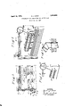
- Fig. 1 is a vertical section through an illustrative embodiment of the invention
- Fig. 2 is a section along the line 2-2 of Fig. 1
- Fig. 3 is a side view partly in section on an enlarged scale showing some of the details
- Fig. 4 is a view similar to Fig. 1 partly broken away showing a modification.
- reference character 1 indicates the steam and water drum of a boiler of the Babcock & Wilcox type having nipples 2 connecting the water space of the steam and water drum to downtake headers 3 that are connected by a bank of inclined tubes 4 to uptake headers 5 that are in turn connected to the steam space of the steam and water drum 1 by means of the circulating tubes 6. Straps 7 suspended from supports 8 may pass around the circulating tubes 6 where they are connected to the headers 5 for supporting the same.
- the steam space of the steam and water drum 1 is connected by a plurality of tubes 9 to the middle portion of the inlet header 11 of the superheater.
- the upper ends of the tubes 9 are open and the tubes are provided with portions 10 inside of the drum 1 at different angles to the tubes 9, thus distributing the open ends of the tubes substantially uniformly along the steam space of the steam and water drum 1 from one end of the drum to the other.
- the tubes extend from the steam space of the steam and water drum through the water space thereof and are curved after they leave the drum, as most clearly indicated in Fig. 2', so as to enter the middle third of the superheater header 11.
- the superheater header 11 is connected by rows of U-tubes 12 to the outlet header 18 at the ends of which steam connections 13 are provided to the'steam main.
- the headers 11 and 13 are parallel to the drum 1 and the ends of these headers extend through the side walls of the furnace.
- the tubes 12 are inclined and parallel to the tubes 4.. Drain pipes 11 are provided at the ends of the header 11, so that the upper legs of the inclined U-tubes 12. can be drained.
- the inlet header 11 is provided with two partitions 14 to divide the header into three portions of substantially the same length, and the outlet header 13is provided with partitions 15, one of them being half way between the partitions 14 and the other two half way between the partitions 14 and the furnace wall. In this way three steam passes are provided through each half of the superheater from the inlet header llto the outlet header .13, as indicated by arrows in .Fig. 2, showing one-half of the superheater;
- Abaftle'l? extends along the upper side of the upper row of tubes 4 from the headers 3 to the support 16 below the superheater header 13, and baffles 18 that may also serve as tube supports extend from the supports 16 across the tubes 12.
- Supports, such as the one illustrated at 19, may be provided below the supports 16 extending across several rows of tubes of the bank 4 to distribute the weight of the superheater upon several rows of these tubes.
- a dry pipe 10 is provided in the steam space of the steam and water drum 1 and the tubes 9 extend from this dry pipe 10 to the superheater inlet header 10.
- a tubular superheater having inlet and outlet headers and having a plurality of steam passes, and tubes extending from the steam space of said steam and water drum through the water space thereof into the middle portion of said inlet header, the ends of said tubes being bent so as to be distributed substantially from one end of the steam space of said drum to the other.
- a tubular superheater having inlet and outlet headers, and tubes extending from the steam space of said steam and water drum through the water space thereof into said inlet header, said tubes having bends inside of said drum towards the ends of said drum.
- a tubular superheater having inlet and outlet headers, and tubes extending from the steam space of said steam and water drum through the water space thereof into said inlet header, said tubes having bends between said drum and header towards the middle of said header.
- a steam boiler a steam and Water separation chamber, steam generating tubes, boiler Walls forming an enclosure for confining heating gases around the tubes, a superheater inlet shorter than the drum and embodied in a header located within the space defined by the walls, a row of small superheater tubes directly communicating with the inlet through a row of tube seats formed in the inlet substantially co-extensive With its length, and a row of small diameter saturated steam tubes bent in the direction of the axis of the drum toward the inlet and extending from the top of the steam and water chamber through the boiler enclosure and having their discharge ends expanded into a row of tube seats extending throughout the length of the superheater inlet so as to provide an even distribution of steam to all of the superheater tubes leading from the inlet.
Landscapes
- Engineering & Computer Science (AREA)
- Mechanical Engineering (AREA)
- General Engineering & Computer Science (AREA)
- Heat-Exchange Devices With Radiators And Conduit Assemblies (AREA)
Description
April 12, 1932. H, KERR; I 1,853,685
SUPERHEATER AND CONNECTIONS TO BOILER DRUMS Filed Nov. 26, 1928 iz-liniu 000000 0000000 NINVENTOR 7 7 V ATTORNEYS Patented Apr. 12, 1932 UNITED STATS Pram. OFFICE HOWARD J. KERR, OF WES'IFIELD, NEW JERSEY, .ASSIGNORTO THE BABGOGK & WILCOX COMPANY, OF BAYONNE, NEW JER$EY, A CORPORATION 0F1 JERSEY SUPERHEATER AND CONNECTIONS TO BOILER DRUMS Application filed November 26, 1928. Serial No. 321,790.
This invention relates to a boiler having a superheater connected to the steam space of the boiler by a plurality of tubes having open ends distributed along the steam space of the boiler. The invention will be understood from the description in connection with the accompanying drawings in which Fig. 1 is a vertical section through an illustrative embodiment of the invention; Fig. 2 is a section along the line 2-2 of Fig. 1; Fig. 3 is a side view partly in section on an enlarged scale showing some of the details; and Fig. 4: is a view similar to Fig. 1 partly broken away showing a modification.
In the drawings reference character 1 indicates the steam and water drum of a boiler of the Babcock & Wilcox type having nipples 2 connecting the water space of the steam and water drum to downtake headers 3 that are connected by a bank of inclined tubes 4 to uptake headers 5 that are in turn connected to the steam space of the steam and water drum 1 by means of the circulating tubes 6. Straps 7 suspended from supports 8 may pass around the circulating tubes 6 where they are connected to the headers 5 for supporting the same.
The steam space of the steam and water drum 1 is connected by a plurality of tubes 9 to the middle portion of the inlet header 11 of the superheater. The upper ends of the tubes 9 are open and the tubes are provided with portions 10 inside of the drum 1 at different angles to the tubes 9, thus distributing the open ends of the tubes substantially uniformly along the steam space of the steam and water drum 1 from one end of the drum to the other. The tubes extend from the steam space of the steam and water drum through the water space thereof and are curved after they leave the drum, as most clearly indicated in Fig. 2', so as to enter the middle third of the superheater header 11.
The superheater header 11 is connected by rows of U-tubes 12 to the outlet header 18 at the ends of which steam connections 13 are provided to the'steam main. The headers 11 and 13 are parallel to the drum 1 and the ends of these headers extend through the side walls of the furnace. The tubes 12 are inclined and parallel to the tubes 4.. Drain pipes 11 are provided at the ends of the header 11, so that the upper legs of the inclined U-tubes 12. can be drained. The inlet header 11 is provided with two partitions 14 to divide the header into three portions of substantially the same length, and the outlet header 13is provided with partitions 15, one of them being half way between the partitions 14 and the other two half way between the partitions 14 and the furnace wall. In this way three steam passes are provided through each half of the superheater from the inlet header llto the outlet header .13, as indicated by arrows in .Fig. 2, showing one-half of the superheater;
The superheaterris' supported above the bank of tubes 4: by means of the'supports 16. Abaftle'l? extends along the upper side of the upper row of tubes 4 from the headers 3 to the support 16 below the superheater header 13, and baffles 18 that may also serve as tube supports extend from the supports 16 across the tubes 12. Supports, such as the one illustrated at 19, may be provided below the supports 16 extending across several rows of tubes of the bank 4 to distribute the weight of the superheater upon several rows of these tubes.
In the modification shown in Fig. 4 a dry pipe 10. is provided in the steam space of the steam and water drum 1 and the tubes 9 extend from this dry pipe 10 to the superheater inlet header 10.
Changes and modifications may be made without departing from the spirit or scope of the invention.
Iclaim:
1. In a boiler having a steam and water drum, a tubular superheater having inlet and outlet headers and having a plurality of steam passes, and tubes extending from the steam space of said steam and water drum through the water space thereof into the middle portion of said inlet header, the ends of said tubes being bent so as to be distributed substantially from one end of the steam space of said drum to the other.
2. In a boiler having a steam and water drum, a tubular superheater having inlet and outlet headers, and tubes extending from the steam space of said steam and water drum through the water space thereof into said inlet header, said tubes having bends inside of said drum towards the ends of said drum.
3. In a boiler having a steam and water drum, a tubular superheater having inlet and outlet headers, and tubes extending from the steam space of said steam and water drum through the water space thereof into said inlet header, said tubes having bends between said drum and header towards the middle of said header.
4. In a steam boiler, a steam and Water separation chamber, steam generating tubes, boiler Walls forming an enclosure for confining heating gases around the tubes, a superheater inlet shorter than the drum and embodied in a header located within the space defined by the walls, a row of small superheater tubes directly communicating with the inlet through a row of tube seats formed in the inlet substantially co-extensive With its length, and a row of small diameter saturated steam tubes bent in the direction of the axis of the drum toward the inlet and extending from the top of the steam and water chamber through the boiler enclosure and having their discharge ends expanded into a row of tube seats extending throughout the length of the superheater inlet so as to provide an even distribution of steam to all of the superheater tubes leading from the inlet.
HOWARD J. KERR.
Priority Applications (1)
| Application Number | Priority Date | Filing Date | Title |
|---|---|---|---|
| US321790A US1853685A (en) | 1928-11-26 | 1928-11-26 | Superheater and connections to boiler drums |
Applications Claiming Priority (1)
| Application Number | Priority Date | Filing Date | Title |
|---|---|---|---|
| US321790A US1853685A (en) | 1928-11-26 | 1928-11-26 | Superheater and connections to boiler drums |
Publications (1)
| Publication Number | Publication Date |
|---|---|
| US1853685A true US1853685A (en) | 1932-04-12 |
Family
ID=23252038
Family Applications (1)
| Application Number | Title | Priority Date | Filing Date |
|---|---|---|---|
| US321790A Expired - Lifetime US1853685A (en) | 1928-11-26 | 1928-11-26 | Superheater and connections to boiler drums |
Country Status (1)
| Country | Link |
|---|---|
| US (1) | US1853685A (en) |
-
1928
- 1928-11-26 US US321790A patent/US1853685A/en not_active Expired - Lifetime
Similar Documents
| Publication | Publication Date | Title |
|---|---|---|
| US1853685A (en) | Superheater and connections to boiler drums | |
| US1633975A (en) | Superheater baffle | |
| US2114224A (en) | Steam boiler | |
| US2067669A (en) | Steam boiler | |
| US2374818A (en) | Steam generator | |
| US2068187A (en) | Heat transfer apparatus applicable to water tube boilers | |
| US1729259A (en) | jacobus | |
| US1906125A (en) | Boiler with interdeck superheater | |
| US1905465A (en) | A cobpobatiom | |
| US1854704A (en) | Water tube boiler and economizer | |
| US1250181A (en) | Steam-boiler. | |
| US1764172A (en) | Locomotive boiler | |
| US1739760A (en) | Assigstox to the babcock | |
| US1934714A (en) | Superheater arrangement in water tube boiler | |
| US1871500A (en) | Water tube boiler | |
| US1969405A (en) | Steam boiler | |
| US2004058A (en) | Boiler | |
| US2072675A (en) | Boiler | |
| US1666276A (en) | Boiler | |
| US2067672A (en) | Fluid heater | |
| GB229920A (en) | Improvements in steam generators of the water tube or flash boiler type | |
| US1927094A (en) | Superheater | |
| US1972893A (en) | Steam boiler | |
| US1940805A (en) | Superheater for water tube boilers | |
| US1738849A (en) | Superheater |