US1853468A - Stovepipe anchor - Google Patents
Stovepipe anchor Download PDFInfo
- Publication number
- US1853468A US1853468A US1853468DA US1853468A US 1853468 A US1853468 A US 1853468A US 1853468D A US1853468D A US 1853468DA US 1853468 A US1853468 A US 1853468A
- Authority
- US
- United States
- Prior art keywords
- chimney
- wire
- pipe
- stovepipe
- clamp
- Prior art date
- Legal status (The legal status is an assumption and is not a legal conclusion. Google has not performed a legal analysis and makes no representation as to the accuracy of the status listed.)
- Expired - Lifetime
Links
Images
Classifications
-
- F—MECHANICAL ENGINEERING; LIGHTING; HEATING; WEAPONS; BLASTING
- F23—COMBUSTION APPARATUS; COMBUSTION PROCESSES
- F23L—SUPPLYING AIR OR NON-COMBUSTIBLE LIQUIDS OR GASES TO COMBUSTION APPARATUS IN GENERAL ; VALVES OR DAMPERS SPECIALLY ADAPTED FOR CONTROLLING AIR SUPPLY OR DRAUGHT IN COMBUSTION APPARATUS; INDUCING DRAUGHT IN COMBUSTION APPARATUS; TOPS FOR CHIMNEYS OR VENTILATING SHAFTS; TERMINALS FOR FLUES
- F23L13/00—Construction of valves or dampers for controlling air supply or draught
- F23L13/02—Construction of valves or dampers for controlling air supply or draught pivoted about a single axis but having not other movement
-
- F—MECHANICAL ENGINEERING; LIGHTING; HEATING; WEAPONS; BLASTING
- F16—ENGINEERING ELEMENTS AND UNITS; GENERAL MEASURES FOR PRODUCING AND MAINTAINING EFFECTIVE FUNCTIONING OF MACHINES OR INSTALLATIONS; THERMAL INSULATION IN GENERAL
- F16L—PIPES; JOINTS OR FITTINGS FOR PIPES; SUPPORTS FOR PIPES, CABLES OR PROTECTIVE TUBING; MEANS FOR THERMAL INSULATION IN GENERAL
- F16L3/00—Supports for pipes, cables or protective tubing, e.g. hangers, holders, clamps, cleats, clips, brackets
Definitions
- the 'structure is characterized by a chimney clamp which hastheadditional function of a stop for limiting the inward movement of the elbow of the'stovepipe and which further functions 3 as an anchor and retention device for the retaining wire.
- a chimney clamp which hastheadditional function of a stop for limiting the inward movement of the elbow of the'stovepipe and which further functions 3 as an anchor and retention device for the retaining wire.
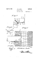
- Figure 1 is an elevational View showing the fragmentary portion of a chimney and stove; pipe together with the elbow retainer and'anchor in place;
- Figure 2 is anenlarged fragmentary section showing the postion of the clamp.
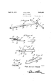
- Figure "3 ' is a perspective view ofa wire holder and guideappliance.
- FIG. 4 is aperspective view of the major part of the clamp.
- Figure 5 is afragmentary elevational view of the stem portion thereof showing the flat take-up and retaining lever.
- Figure (Sis a view like Figure 5 showing the lever swung over to wire retaining position.- y
- Figure 7 is a detail section on an'enlarged scale taken onthe plane of the line 77 of Figure Sis a perspective detail view of the lever or latch, f f
- Figure 9 is a perspective view of the adjustable retaining element of the chimney p f l r f
- the primary part of the clamp generally designated by the reference character 10 in Figure 4 is of a composite structure within itself. For instance, it includes a part 11 in the nature of a chimney abutmentand this is of a cruciformconfiguration and includes a pair of outstanding horizontal arms 12 which engage the inner wall of the flue of the chimney, 13as seen in Figure 2. In addition there is a depending centralized finger, 14 which alsoengages the wall of the flue. Then too, there is an upstanding V-shaped part.15 having a'bent orhooked apex portion 16.
- This feature 16 constitutesa stop for limiting the inward sliding movement of the'portion 17 of the stove pipe generally represented at 18.
- f Thefinger 14 constitutes'a down-bent end orthe inner end o fthe stem 19.
- the longitudinal edge portions of this part 19" are formed with serrations 2O defining lon 'tudinally spaced keeperseats.
- in igure 6 is-a bent stop co-operating with the piv-' retaining detent 28 (see Figure 7) as shown.-
- FIG. 9 designates'the adjustable part of the chimney clamp
- This is in the nature of a slide and includes atongue. 30 and a downbent flange 31 having a substantially T-shaped opening 32 formed therein.
- the restricted portion of this opening is adapted "to. be selectively dropped into the comple-' mental keeper seat 20. This permits bodily shifting and adjustment of the slide and then clamping position whereby, to hold the complete clamp in firm anchorage on the chimney as seen in' Figure 2.
- the clamp functions as stated, as a wire tightener as well as an an- Chorage device for the wire. a a
- the ,gist of the invention is in the provision of a structure char acterized by a chimney; clamp.
- This clamp comprises the structurerepresented F igured, and the complemental slide represented in Figure 9. The slide is adjusted to the position. represented in Figure 2, thereby and is associated with the especially bent clip 33.
- the clamp also has the additional function of providing bracing means for the clamp itself, as well as stop means for limiting the inward sliding movement of the branch -17 of the Stovepipe.
- l. In combination withachimney, a stove pipe" and an elbOW'COB- lected.with the pipe, a,- niember locatedin the chimney and having a.- pa t ac ng as a stop f r th end of h p pe, a stem having its inner. end connected with s id member and s i t m pa ing: through the stove pipe open ng in the chimney, a wire connected wi h the elbow, a lide adjustably mounted on said stem, a latch s op 0 t e Outer end ofthe stem, a lever pivotally mounted. on said outer end; and (so-operable.
Landscapes
- Engineering & Computer Science (AREA)
- General Engineering & Computer Science (AREA)
- Mechanical Engineering (AREA)
- Chemical & Material Sciences (AREA)
- Combustion & Propulsion (AREA)
- Supports For Pipes And Cables (AREA)
Description
April 12, 1932. E, s n- 1,853,468
STOVEPIPE ANCHOR Filed May 6, 1930 2 Sheets-Sheet l It j/ Invenlor April 12, 1932. E G sMlTH 1,853,468
STOVEPIPE ANCHOR Filed May 6, 1930 2 Sheets-Sheet 2 m ma mm Invenlor A llomey Patented Apr. 12, 1932 UNITED s ATss TE T ounce ELLA eamvnn smrn, or cnALLIs, rnmo s rovnrrrn'nivonon I Application file'rl ma it is not possible to drive a nail intofi it.
Therefore it becomes necessary to place the hook or screw into the wall at some distance away from the pipe. to stand out conspicuously and detract'from the appearance of the room. These common means usually employed to secure thesto've- V pipes are also usually unsafe; sincethe nails, etc., become loose, or the wire slips, letting the pipe slip out from the chimney. This would permit the flame to i nite the paper and cause a fire, or at least, a low smoke and soot to escape into the room. In addition to the advantages of this invention mentioned'above, the inconvenience of the stovepipe slipping too far into the chimney has been overcome. The pipe'can only enter the chimney now to the edge of the entrance of'the flue, and cannot enter to cut 01f the draft.
Practically no tools are needed toiinstall this contraption, and it can be done in minimum time, by inexperienced:personsyeven thougha fire is in the stove. It is practically impossible for the holder to become loose within the chimney, or for the wires to become loose. It has no nuts'or bolts to become loose, and it can be constructed at a nominal cost. 7 i f Briefly stated, the 'structureis characterized by a chimney clamp which hastheadditional function of a stop for limiting the inward movement of the elbow of the'stovepipe and which further functions 3 as an anchor and retention device for the retaining wire. Other structural features of the improved This causes the wires 1930. Serial. lt'o. 450,138.
device will become more readily apparent from' thefollowing description and drawmgs.
In the drawings: e Figure 1 is an elevational View showing the fragmentary portion of a chimney and stove; pipe together with the elbow retainer and'anchor in place; i Figure 2 is anenlarged fragmentary section showing the postion of the clamp. Figure "3 'is a perspective view ofa wire holder and guideappliance. V
Figure 4 is aperspective view of the major part of the clamp. V
Figure 5 is afragmentary elevational view of the stem portion thereof showing the flat take-up and retaining lever.
Figure (Sis a view like Figure 5 showing the lever swung over to wire retaining position.- y
Figure 7 is a detail section on an'enlarged scale taken onthe plane of the line 77 of Figure Sis a perspective detail view of the lever or latch, f f
'Figure 9 is a perspective view of the adjustable retaining element of the chimney p f l r f The primary part of the clamp generally designated by the reference character 10 in Figure 4 is of a composite structure within itself. For instance, it includes a part 11 in the nature of a chimney abutmentand this is of a cruciformconfiguration and includes a pair of outstanding horizontal arms 12 which engage the inner wall of the flue of the chimney, 13as seen in Figure 2. In addition there is a depending centralized finger, 14 which alsoengages the wall of the flue. Then too, there is an upstanding V-shaped part.15 having a'bent orhooked apex portion 16. This feature 16"constitutesa stop for limiting the inward sliding movement of the'portion 17 of the stove pipe generally represented at 18. f Thefinger 14; constitutes'a down-bent end orthe inner end o fthe stem 19. l? The longitudinal edge portions of this part 19" are formed with serrations 2O defining lon 'tudinally spaced keeperseats. At 21, in igure 6 is-a bent stop co-operating with the piv-' retaining detent 28 (see Figure 7) as shown.-
'- permits it to be dropped down to the desired oted latch 22. The latch is pivoted on the This detent is adapted to. permit the wire to pass therebeneath as indicatedin'Figure 6 to prevent accidental opening of the latch, In other words, after the latch is closed to the position seen in Figure 6, the wire is snap ed beneath the, detent or projection 28 t us holding the wire in 'place.
I now invite attention to numeral 29 in Figure 9, which designates'the adjustable part of the chimney clamp This is in the nature of a slide and includes atongue. 30 and a downbent flange 31 having a substantially T-shaped opening 32 formed therein. The restricted portion of this opening is adapted "to. be selectively dropped into the comple-' mental keeper seat 20. This permits bodily shifting and adjustment of the slide and then clamping position whereby, to hold the complete clamp in firm anchorage on the chimney as seen in'Figure 2. The clamp functions as stated, as a wire tightener as well as an an- Chorage device for the wire. a a
' The opposite end of the wire is associated with the continuously bent clip 33 (see Figure .3) in such a manner as to permit this end portion of the wire to be encircled or passed around the elbow as indicated at 34 in Fig ure 1; By thus passing the wire aroundthe elbow and then returning it through the guide eye 35 of the clip, then sending it through and connecting it with the apertures 2a in the latch,.tl1e,desired slack in the wire maybe taken up. 'Y
- Takefor example, the anchored right-hand end 25 of the wire in Figure 5, it will be seen thatby swinging the latch .23 over to. the
position represented in Figure 6 and snapping the wireunderneath of the head or projection 28, the'wire'will be caused to draw the end of the Stovepipe into the chimney to the point seen in F igure2. The pipe cannot enter the'chimney hole to block the passage for this is 5 prevented by the upstanding fea- 'tures15 and 16 (see Figure 4).
The ,gist of the invention, it will be observed, is in the provision of a structure char acterized by a chimney; clamp. This clamp comprises the structurerepresented F igured, and the complemental slide represented in Figure 9. The slide is adjusted to the position. represented in Figure 2, thereby and is associated with the especially bent clip 33. The clamp also has the additional function of providing bracing means for the clamp itself, as well as stop means for limiting the inward sliding movement of the branch -17 of the Stovepipe.
ltis thought that persons skilled in the art to which the'invention relates will be able to obtain a clear understanding of theinvention afterconsidering the description in connection with-the. dr wings, Therefore, a more lengthy description is regarded as un necessary. 1 e
Minor. changes in shape, size, and rearnngementsof details coming within the field of invention claimed may be resorted to in actu p a c if desired v 'Iclaim:
l.= In combination withachimney, a stove pipe" and an elbOW'COB- lected.with the pipe, a,- niember locatedin the chimney and having a.- pa t ac ng as a stop f r th end of h p pe, a stem having its inner. end connected with s id member and s i t m pa ing: through the stove pipe open ng in the chimney, a wire connected wi h the elbow, a lide adjustably mounted on said stem, a latch s op 0 t e Outer end ofthe stem, a lever pivotally mounted. on said outer end; and (so-operable. w th said s op, said lever being formed with apertures for selec i djustable conn c ion of the Wi17 thereto whereby movement of the lever against, the stop l au the e o ore the bow inwardly to ause the end. Q the P p 0 engage the op 011 th m mb r with- .11. the chimney. j 7 a 2. In combination with a chimney having an opening therein; a pipe having ne d lqcated in said ope ing and an elb w 1 he pipe, a member located. in the chimney adjacent the inne en of the op ningia d having a part acting as a stop for theinner end'of the pip a stem pas ing through the opening and having its inner end connected to Said member, a; leverpivoted to the outer-end of the stem, 1% wire connected with the elbow, means. for adjustably connecting the wire to the lever whereby when the lev'er is swung in weirdly, the wire will because-d to move the elbowand pipe to a p sitionwhere theinner endof the-pipe will engage the stop.
3. In combination with a chimney having an openlng therein, a pipe having'one end located in said ,openingand an elbow on vthe pipe, am m er locatedfi thechimney adjacent. the innerend ftheopening, and. having a part acting as a I stop. forv thefinnr-end o the pipea s ern passing through the'opening and having its inner end connected to said sinember, alever pivot d oithe ut r' nd of the stem, a wire connected with the elbow, means for adjustably connecting the wire to the lever whereby when the lever is swung inwardly, the wire will be caused to move the elbow and pipe to a position where the inner end of the pipe will engage the stop, and a chimney engaging member adjustably mounted on the stem for engaging the outer wall of the chimney, said member having an inwardly extending part for engaging a wall of the chimney opening.
In testimony whereof I afiix my signature.
MRS. ELLA GARNER SMITH.
Publications (1)
| Publication Number | Publication Date |
|---|---|
| US1853468A true US1853468A (en) | 1932-04-12 |
Family
ID=3423651
Family Applications (1)
| Application Number | Title | Priority Date | Filing Date |
|---|---|---|---|
| US1853468D Expired - Lifetime US1853468A (en) | Stovepipe anchor |
Country Status (1)
| Country | Link |
|---|---|
| US (1) | US1853468A (en) |
-
0
- US US1853468D patent/US1853468A/en not_active Expired - Lifetime
Similar Documents
| Publication | Publication Date | Title |
|---|---|---|
| US2529589A (en) | Mousetrap | |
| US1853468A (en) | Stovepipe anchor | |
| US3175264A (en) | Sliding logging hook | |
| US242132A (en) | Gas-lighter | |
| US805631A (en) | Clamp. | |
| US863059A (en) | Vent for the escape of combustion-gases in burning buildings. | |
| US1097423A (en) | Stovepipe-fastener. | |
| US218596A (en) | Improvement in automatic dampers | |
| US1862725A (en) | Dilator | |
| US2633854A (en) | Cigarette extinguisher | |
| US1406422A (en) | Hack saw | |
| US1743685A (en) | Safety gas-valve lock | |
| US1501370A (en) | Smoking pipe | |
| US4265217A (en) | Remote fireplace damper control | |
| US1435554A (en) | Stovepipe holder | |
| US2037302A (en) | Safety gas valve | |
| US1750861A (en) | Ignition and genebating means fob gasoline lamps | |
| US696854A (en) | Lamplighter and match-extinguisher. | |
| US1821204A (en) | Furnace damper control | |
| US1543048A (en) | Lamp-burner attachment | |
| US1991565A (en) | Adjustable holding device | |
| US1943482A (en) | Cleanout for stovepipes ob elbows | |
| US863325A (en) | Locking attachment for smoke-pipes. | |
| US1564176A (en) | Fuel-saving device | |
| US1371274A (en) | Hose-clamp |