US1852861A - Cooling apparatus for reciprocating pistons - Google Patents
Cooling apparatus for reciprocating pistons Download PDFInfo
- Publication number
- US1852861A US1852861A US525764A US52576431A US1852861A US 1852861 A US1852861 A US 1852861A US 525764 A US525764 A US 525764A US 52576431 A US52576431 A US 52576431A US 1852861 A US1852861 A US 1852861A
- Authority
- US
- United States
- Prior art keywords
- piston
- cooling medium
- pipe
- cooling apparatus
- reciprocating
- Prior art date
- Legal status (The legal status is an assumption and is not a legal conclusion. Google has not performed a legal analysis and makes no representation as to the accuracy of the status listed.)
- Expired - Lifetime
Links
- 238000001816 cooling Methods 0.000 title description 5
- 239000002826 coolant Substances 0.000 description 12
- 238000002485 combustion reaction Methods 0.000 description 6
- 239000007788 liquid Substances 0.000 description 6
- 238000010276 construction Methods 0.000 description 1
- 239000000498 cooling water Substances 0.000 description 1
- XLYOFNOQVPJJNP-UHFFFAOYSA-N water Substances O XLYOFNOQVPJJNP-UHFFFAOYSA-N 0.000 description 1
Images
Classifications
-
- F—MECHANICAL ENGINEERING; LIGHTING; HEATING; WEAPONS; BLASTING
- F01—MACHINES OR ENGINES IN GENERAL; ENGINE PLANTS IN GENERAL; STEAM ENGINES
- F01P—COOLING OF MACHINES OR ENGINES IN GENERAL; COOLING OF INTERNAL-COMBUSTION ENGINES
- F01P3/00—Liquid cooling
- F01P3/06—Arrangements for cooling pistons
- F01P3/10—Cooling by flow of coolant through pistons
Definitions
- osoee srrvrnrnn or nannomswirznnnnum, nssrenoit 510 T rinuoesnnznn FRERES SOCIE'IE ANONYME, or wmrnarnun; swirznnnnnn COOLING APPARATUS r03 itnoirnocn'r rrorisrons Application filed. March 27, 1931, Serial No. 525,764, and in SizritzerlandJune 7,1930.
- the receiv ng orifice or pipe communicates with the interior of the piston through an intermediate chamber containing air, whereby pressure 1mpulses or surges in the liquid carried in the reciprocating part of the system and tending to cause flow of liquid towards the fixed nozzle are damped and back pressure on the et thus reduced.
- the intermediate chamber carries the receiving pipe and is arranged 1n that part of the system which reciprocates with the piston, while a non-return valve is preferably'provided to prevent returnfiow of the liquid from the interior of the piston back into therchamber.
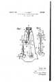
- Fig. 1 is an'end elevation, partly 1n section of the improved engine
- Fig. 2 is a fragmentary, vertical, sectional 45 detail of Fig. 1.
- the engine comprises a cylinder a, a water cooled piston b, apiston rod 10 and a crosshead (ZQ
- the crosshead is connected to the crankshaft f by a'connecting rod e, and the S engine is supportedon a frame g.
- the cooling water supplied through a pipe 7L issues'from a nozzle in .the form of a jet 11 parallel to the path of the piston" andenters a receiving pipe Z telescopically movable within :anouter-tube o having an overflow or 5 discharge pipe p.
- the pipe-Z. is rigidlyconnected to and COlTllllLllllCfltQSWltll a chamber m containingairand carried onthe crosshead (Z, this chamber communicating through a non-returnvalve a, a pipe 7: and a passage is 0 I impulses thus produced so that the intensity of back pressure impulses which would otherwise result on the jet z is reduced and consefliquent loss of cooling medium avoided.
- the non-return valve it serves to prevent the return of liquid from the interior of the piston to the chamber m and thus assist the benev ficial actionof the air in the chamber m.
Landscapes
- Engineering & Computer Science (AREA)
- Chemical & Material Sciences (AREA)
- Combustion & Propulsion (AREA)
- Mechanical Engineering (AREA)
- General Engineering & Computer Science (AREA)
- Lubrication Of Internal Combustion Engines (AREA)
Description
P l o. SIMMEN 1,852,861
COOLING APPARATUS FOR RECIPROCATING PISTONS Filed March 27, 1931 INVENTU 6%,
Patented: Apr. 5,
ST AT ESP car es;
osoee srrvrnrnn, or nannomswirznnnnum, nssrenoit 510 T rinuoesnnznn FRERES SOCIE'IE ANONYME, or wmrnarnun; swirznnnnnn COOLING APPARATUS r03 itnoirnocn'r rrorisrons Application filed. March 27, 1931, Serial No. 525,764, and in SizritzerlandJune 7,1930.
This invention relates to cooling apparatus for reciprocating P13130115. of; internal combustion engines and of the kind in which liquid cooling medium is delivered from a= 5 fixed nozzle in the form of a jet parallel to the path of the piston and enters a receiving orifice or pipe carried by the piston or a member secured thereto and communlcating with the interior :of the piston.
I t C type, owing to the inertia of the cooling medium which reciprocates with the p ston, this cooling medium tends at certain parts of the stroke toflow back through the or fice and thereby oauseback pressure on the et issuing from the nozzle, and the present invention has for its object to provide improved apparatus by which this back pressure Wlll be reduced.
According to this inventlon the receiv ng orifice or pipe communicates with the interior of the piston through an intermediate chamber containing air, whereby pressure 1mpulses or surges in the liquid carried in the reciprocating part of the system and tending to cause flow of liquid towards the fixed nozzle are damped and back pressure on the et thus reduced. T
Conveniently the intermediate chamber carries the receiving pipe and is arranged 1n that part of the system which reciprocates with the piston, while a non-return valve is preferably'provided to prevent returnfiow of the liquid from the interior of the piston back into therchamber.
. Two constructions according to the invention are illustrated diagrammatically by way of example in the accompanying drawings as applied to a vertical double acting internal combustion engine.
In thesedrawings, Fig. 1 is an'end elevation, partly 1n section of the improved engine, Fig. 2 is a fragmentary, vertical, sectional 45 detail of Fig. 1.
The engine comprises a cylinder a, a water cooled piston b, apiston rod 10 and a crosshead (ZQ The crosshead is connected to the crankshaft f by a'connecting rod e, and the S engine is supportedon a frame g.
Hitherto, in cooling apparatus of this The cooling water supplied through a pipe 7L issues'from a nozzle in .the form of a jet 11 parallel to the path of the piston" andenters a receiving pipe Z telescopically movable within :anouter-tube o having an overflow or 5 discharge pipe p. The pipe-Z. is rigidlyconnected to and COlTllllLllllCfltQSWltll a chamber m containingairand carried onthe crosshead (Z, this chamber communicating through a non-returnvalve a, a pipe 7: and a passage is 0 I impulses thus produced so that the intensity of back pressure impulses which would otherwise result on the jet z is reduced and consefliquent loss of cooling medium avoided. The non-return valve it serves to prevent the return of liquid from the interior of the piston to the chamber m and thus assist the benev ficial actionof the air in the chamber m.
I claim: 7
1. In an internal combustion engine the combination with a reciprocating piston, of a fixed nozzle adapted to deliver a cooling medium in theform of a ct parallel to the path 85 of the piston, of a jet receiving orifice connected to the piston by a pipe communicating with the interior of'the piston and of achamber containing air in the passage through which the cooling medium flows from the re- 96 ceiving orifice to the piston.
2. In an internal combustion engine the combination with a reciprocating piston, of a fixed nozzle adapted to deliver a cooling medium in the form of a jet parallel to the path of the piston, of a jet receiving orifice connected to the piston by a pipe communicat ing with the interior of the piston and of a chamber containing-s air. in the passage through which the cooling medium flows from 00 the receiving orifice to the piston, said air chamber being arranged in a part of the system reciprocating with the piston.
3. In an internal combustion engine the combination with a reciprocating piston, of a fixed nozzle adapted to deliver a cooling medium in the form of a jet parallel to the path of the piston, of a jet receiving orifice connected to the piston by a pipe communicating with the interior of the piston and of a chamber containing air in the passage through which the cooling medium flows from the receiving orifice to the piston, a nonreturn valve being provided to prevent flow of the liquid from the interior of the piston back into the air chamber.
4. In an internal combustion engine the combination with a reciprocating piston, of a fixed nozzle adapted to deliver a cooling medium in the form of a jet parallel to the path of the piston, of a jet receiving orifice connected to the piston by a pipe communicating with the interior of the piston and of a chamber containing air in the passage through which the cooling medium flows from the receiving orifice to the piston, the receiving orifice being carried by the air chamber.
In testimony whereof I have aflixed my sig nature.
OSCAR SIMMEN.
Applications Claiming Priority (1)
| Application Number | Priority Date | Filing Date | Title |
|---|---|---|---|
| CH1852861X | 1930-06-07 |
Publications (1)
| Publication Number | Publication Date |
|---|---|
| US1852861A true US1852861A (en) | 1932-04-05 |
Family
ID=4566517
Family Applications (1)
| Application Number | Title | Priority Date | Filing Date |
|---|---|---|---|
| US525764A Expired - Lifetime US1852861A (en) | 1930-06-07 | 1931-03-27 | Cooling apparatus for reciprocating pistons |
Country Status (1)
| Country | Link |
|---|---|
| US (1) | US1852861A (en) |
Cited By (3)
| Publication number | Priority date | Publication date | Assignee | Title |
|---|---|---|---|---|
| US2759461A (en) * | 1953-06-16 | 1956-08-21 | Maybach Motorenbau Gmbh | Oil-cooled piston for a high speed internal combustion engine, particularly for a diesel motor for vehicles |
| US3444844A (en) * | 1966-03-31 | 1969-05-20 | Sulzer Ag | Crosshead-type internal combustion piston engine having liquid-cooled pistons |
| US4724800A (en) * | 1986-08-15 | 1988-02-16 | Southwest Research Institute | Ringless piston engine |
-
1931
- 1931-03-27 US US525764A patent/US1852861A/en not_active Expired - Lifetime
Cited By (3)
| Publication number | Priority date | Publication date | Assignee | Title |
|---|---|---|---|---|
| US2759461A (en) * | 1953-06-16 | 1956-08-21 | Maybach Motorenbau Gmbh | Oil-cooled piston for a high speed internal combustion engine, particularly for a diesel motor for vehicles |
| US3444844A (en) * | 1966-03-31 | 1969-05-20 | Sulzer Ag | Crosshead-type internal combustion piston engine having liquid-cooled pistons |
| US4724800A (en) * | 1986-08-15 | 1988-02-16 | Southwest Research Institute | Ringless piston engine |
Similar Documents
| Publication | Publication Date | Title |
|---|---|---|
| US1852861A (en) | Cooling apparatus for reciprocating pistons | |
| GB450645A (en) | Improvements in reciprocating pumps | |
| US1560492A (en) | Internal-combustion engine | |
| US1603173A (en) | Internal-combustion engine | |
| US1928033A (en) | Cooling apparatus for reciprocating pistons | |
| GB392840A (en) | Improvements in or relating to cooling apparatus for reciprocating pistons | |
| US1511971A (en) | Air pump | |
| GB409937A (en) | Improvements in or relating to aircraft catapulting apparatus | |
| GB313231A (en) | Improvements in driving gear for use with internal combustion engines | |
| US2329040A (en) | Lubricator oil control valve | |
| US1551122A (en) | Device for placing vehicles in predetermined positions | |
| US1680883A (en) | Internal-combustion engine | |
| DE534346C (en) | Device for venting centrifugal or other pumps | |
| DE532729C (en) | Piston cooling device for internal combustion engines | |
| DE528935C (en) | Device for cooling pistons, in particular internal combustion engines | |
| GB357929A (en) | Improvements in or relating to cooling apparatus for reciprocating pistons | |
| DE463495C (en) | Oil wiping piston ring for piston engines, especially internal combustion engines | |
| GB208670A (en) | Twin piston engine | |
| US1658115A (en) | Primer for internal-combustion engines | |
| GB358799A (en) | Improvements in or relating to cooling apparatus for reciprocating pistons | |
| US1942369A (en) | Auxiliary distributing valve for locomotives | |
| US1414610A (en) | Lubricating apparatus | |
| DE589110C (en) | Injection device for internal combustion engines | |
| DE723951C (en) | Working method for reciprocating engines | |
| DE428217C (en) | Pressure reducing valve for compressed air |