US185285A - Improvement in perforating-stafvips - Google Patents
Improvement in perforating-stafvips Download PDFInfo
- Publication number
- US185285A US185285A US185285DA US185285A US 185285 A US185285 A US 185285A US 185285D A US185285D A US 185285DA US 185285 A US185285 A US 185285A
- Authority
- US
- United States
- Prior art keywords
- stamp
- improvement
- stafvips
- perforating
- plunger
- Prior art date
- Legal status (The legal status is an assumption and is not a legal conclusion. Google has not performed a legal analysis and makes no representation as to the accuracy of the status listed.)
- Expired - Lifetime
Links
- 238000010276 construction Methods 0.000 description 2
- 239000002184 metal Substances 0.000 description 2
- CIWBSHSKHKDKBQ-JLAZNSOCSA-N Ascorbic acid Chemical compound OC[C@H](O)[C@H]1OC(=O)C(O)=C1O CIWBSHSKHKDKBQ-JLAZNSOCSA-N 0.000 description 1
- 101100001674 Emericella variicolor andI gene Proteins 0.000 description 1
- 239000003550 marker Substances 0.000 description 1
Images
Classifications
-
- B—PERFORMING OPERATIONS; TRANSPORTING
- B43—WRITING OR DRAWING IMPLEMENTS; BUREAU ACCESSORIES
- B43K—IMPLEMENTS FOR WRITING OR DRAWING
- B43K29/00—Combinations of writing implements with other articles
- B43K29/18—Combinations of writing implements with other articles with hand tools, e.g. erasing knives
- B43K29/185—Combinations of writing implements with other articles with hand tools, e.g. erasing knives with cheque protectors
Definitions
- A represents the handle, in the lower end of which, near one side, is inserted a stem, B, provided on its outer end with the postmarliiug device C.
- the stein B is slotted longitndinallyibr a suitable distance, and through said slot is passed a bolt or pin, a, to guide and limit the movement of said stem.
- a spiral spring, E' which forces and holds the stem outward until the device is brought down to mark the letter, when the spring', ot' course, yields.
- Within the handle A is also another plunger, l), forced outward by means of a spiral spring; E, as shown.
- a shaft, G which moves with the plunger, and in addition thereto is rotated v by means of a pin, I), passing through a slot in the plunger, and entering a spiral groove in the shaft.
- the two plun gers, with their spiral springs, are placed within a double-barreled metal casing, H, secured in the wooden handle A in any suitable manner.
- the end of the shaft G forms a screw-rod, d, upon which are two nuts, e,for adjusting the stamp-cam celin g device.
- This device consists of a plate, f, which is perforated with a number of rows of small holes, arranged as shown in Fig.
- the canceler f can 'ne adjusted upon the rod d as required, and need liever be taken ott' for sharpening, be :anse as it wears down on the edge, before the teeth formed by the tirst row ot' holes are entirely worn out, ⁇ the metal is worn through into the next row of holes, and thus forming a new set of teeth.
- the rod d with its nuts and canceler, is surrounded by a cage, I, screwed upon the lower end of the plunger D, as shown;
- the eanceler in tubular form, it may be used in a straight form, as shown in Figs. 3 and 4:.
- two plates are placed side by side in a box, J, and connected by elbow-levers, or other mechanical deviccs, in such a manner that when pressed down upon the stamp the plates will not only yield, but also move lengthwise in opposite directions and cancel the stamp.
Landscapes
- Adornments (AREA)
Description
c, v. BRINKERHOFF.
P-ERFORATING STAMP.
Patented Dec. 12. 187.
ATTORNEYS.
THE GRAPHIC C0. NM
Ulvriarn ST CHARLES V. BRINKERHOFF, OF MOUNT CLEMENS, MICHIGAN.
IMPROVEMENT IN PERFORATlNG-STAMPS.
Specification forming part of Letters Patent No. 185,285, dated December 12, 1876; application led August 29, Y1876.
To all whom it may concern:
Be it known that I, CHARLES V. BRINKER- HOFF, of Mount Clemens, in the county of Macomb, and in the State ofMichigan,have invented certain new and useful Improvements in Hand Stamp-Canceler; and do hereby declare that the following is a full, clear, and exact description thereof, reference being had to the accompanying drawings, and to the letters of reference marked thereon, making a part of this specification.
The nature ot' my invention consists in the construct-ion and arrangement of a stamp-canceling and postmarking device, as will be hereinafter more fully set forth.
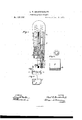
In order to enable others skilled in the art to which my invention appertains to make and use the same, I will now proceed to describe its construction and operation, referring to the annexed drawing, in which- Figure l is a section of my stamp-canceling and post-marking device. Fig. 2 is a detailed view of a part thereof. Figs. 3 and 4 show a modication of the same.
A represents the handle, in the lower end of which, near one side, is inserted a stem, B, provided on its outer end with the postmarliiug device C. The stein B is slotted longitndinallyibr a suitable distance, and through said slot is passed a bolt or pin, a, to guide and limit the movement of said stem. Vithin the handle, above the stem, is a spiral spring, E', which forces and holds the stem outward until the device is brought down to mark the letter, when the spring', ot' course, yields. Within the handle A is also another plunger, l), forced outward by means of a spiral spring; E, as shown. within the same is a shaft, G, which moves with the plunger, and in addition thereto is rotated v by means of a pin, I), passing through a slot in the plunger, and entering a spiral groove in the shaft. The two plun gers, with their spiral springs, are placed within a double-barreled metal casing, H, secured in the wooden handle A in any suitable manner. The end of the shaft G forms a screw-rod, d, upon which are two nuts, e,for adjusting the stamp-cam celin g device. This device consists of a plate, f, which is perforated with a number of rows of small holes, arranged as shown in Fig. 2-that is to say, the holes of each row are opposite the spaces between the holes of the This plunger is hollow, andadjoining row on each side. The last row of these perforations is made through the edge of the plate, forming, as it were, a seriesof teeth. This plate is bent in tubular form, placed on the lower end of the screw-rod d, and held by means of a collar, li, surrounding the tube and feathered to the rod, and then fastened by a set-screw.
In using this'device, as it is brought down upon the letter the marker C marks the letter, and at the same time the cancelerj, striking the letter, is forced upward andI rotated, thereby tearing the stamp, so as to render it untlt for use, or, in other words, effectually canceling the same.
The canceler f can 'ne adjusted upon the rod d as required, and need liever be taken ott' for sharpening, be :anse as it wears down on the edge, before the teeth formed by the tirst row ot' holes are entirely worn out,`the metal is worn through into the next row of holes, and thus forming a new set of teeth.
The rod d, with its nuts and canceler, is surrounded by a cage, I, screwed upon the lower end of the plunger D, as shown;
Instead of using the eanceler in tubular form, it may be used in a straight form, as shown in Figs. 3 and 4:. In that case two plates are placed side by side in a box, J, and connected by elbow-levers, or other mechanical deviccs, in such a manner that when pressed down upon the stamp the plates will not only yield, but also move lengthwise in opposite directions and cancel the stamp.
Having thus fully described my invention, what I claim as new, and desire to secure by Letters Patent, is-
In a hand stamp-canceler, the combination of the perforated canceling-platef, rotating shaft G, with rod d, plunger D, spring E, and the stem or plunger B, with post-marking device C and spring E', all constructed as described, and arranged for operation within a handle, A, substantially as and for the purposes herein set forth.
In testimony that I claim the foregoing I have hereunto set my hand this 24thday of August, 1876.
oHAs. vl BRINKERHOFF.
Witnesses:
J. M. MASON, WM. L. BRAMHALL.
Publications (1)
| Publication Number | Publication Date |
|---|---|
| US185285A true US185285A (en) | 1876-12-12 |
Family
ID=2254690
Family Applications (1)
| Application Number | Title | Priority Date | Filing Date |
|---|---|---|---|
| US185285D Expired - Lifetime US185285A (en) | Improvement in perforating-stafvips |
Country Status (1)
| Country | Link |
|---|---|
| US (1) | US185285A (en) |
-
0
- US US185285D patent/US185285A/en not_active Expired - Lifetime
Similar Documents
| Publication | Publication Date | Title |
|---|---|---|
| US185285A (en) | Improvement in perforating-stafvips | |
| US726086A (en) | Marking implement. | |
| US588833A (en) | Post-hole digger | |
| US862918A (en) | Combination currycomb and brush. | |
| US276817A (en) | Curry-comb | |
| US882379A (en) | Attachment for planters. | |
| US262698A (en) | Walter h | |
| US214720A (en) | Improvement in chamber-drills for drilling rock for blasting purposes | |
| US115503A (en) | Improvement in rock-drills | |
| US112092A (en) | Improvement in meat-tenderers | |
| US189000A (en) | Improvement in perforating-staivjps | |
| US426094A (en) | Island | |
| US117997A (en) | Improvement in scrubber and mop-heads | |
| US183721A (en) | Improvement in feather-renovators | |
| US598856A (en) | Joseph carter and william richmond | |
| US193781A (en) | Improvement in leaf-turners | |
| US167305A (en) | Improvement in harness-hames | |
| US114772A (en) | Improvement in feeders for wax tapers | |
| US447417A (en) | Mole-trap | |
| US242113A (en) | Dayid b | |
| US210652A (en) | Improvement in meat-tenderers | |
| US184710A (en) | Improvement in corn-planters | |
| US179868A (en) | Improvement in tube-expanders | |
| US185935A (en) | Improvement in cradle-snath bands | |
| US198962A (en) | Improvement in watchmen s time-checks |