US1852851A - Saw band - Google Patents
Saw band Download PDFInfo
- Publication number
- US1852851A US1852851A US533134A US53313431A US1852851A US 1852851 A US1852851 A US 1852851A US 533134 A US533134 A US 533134A US 53313431 A US53313431 A US 53313431A US 1852851 A US1852851 A US 1852851A
- Authority
- US
- United States
- Prior art keywords
- saw
- drum
- bands
- band
- saw band
- Prior art date
- Legal status (The legal status is an assumption and is not a legal conclusion. Google has not performed a legal analysis and makes no representation as to the accuracy of the status listed.)
- Expired - Lifetime
Links
- 229920000742 Cotton Polymers 0.000 description 6
- 238000004140 cleaning Methods 0.000 description 4
- 239000002184 metal Substances 0.000 description 4
- 238000010276 construction Methods 0.000 description 3
- 239000010813 municipal solid waste Substances 0.000 description 2
- 229910000831 Steel Inorganic materials 0.000 description 1
- 239000000463 material Substances 0.000 description 1
- 239000000203 mixture Substances 0.000 description 1
- 239000004576 sand Substances 0.000 description 1
- 239000010959 steel Substances 0.000 description 1
Images
Classifications
-
- D—TEXTILES; PAPER
- D01—NATURAL OR MAN-MADE THREADS OR FIBRES; SPINNING
- D01B—MECHANICAL TREATMENT OF NATURAL FIBROUS OR FILAMENTARY MATERIAL TO OBTAIN FIBRES OF FILAMENTS, e.g. FOR SPINNING
- D01B1/00—Mechanical separation of fibres from plant material, e.g. seeds, leaves, stalks
- D01B1/02—Separating vegetable fibres from seeds, e.g. cotton
- D01B1/04—Ginning
- D01B1/08—Saw gins
Definitions
- This invention relatesto a novel saw band construction for use in cotton extracting and cleaning machines
- Saw bands as usually constructed for this purpose are made from strips of steel the side edges of which arey bentrout at right angles to form flanges, and saw teeth are then cut in these ianges. These bands are then placed at regular intervals around' ⁇ the surface of a k drum and nailed or screwed thereto through equally spaced apertures provided in the band throughoutits length. In this manner saw cylinders of any desired size, such as are used in extracting the cotton from a mixture of cotton, hulls and trash, are formed, each saw band providing two rows of teeth eX- y tending around the drum.
- My invention therefore, consists in form# ing a saw band for cotton cleaning machines with the body portion lying betweeny the two saw toothed ianges concaved on its under side.
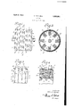
- l l v V rlhe invention is illustrated inthe accom-'f panying drawings in which- Figure l 1s a 'view 7in front elevation v'of a portion of a saw cylinder having saw bandsof4 ,v y my invention secured aroundits outer surface.
- Figure -2 is a section on theline Y2-'2 'of Figure 1.
- I A' Figure 3 is an enlarged brokendetail view, ⁇ showing, particularly, themanner in which the sawl bands are secured to a drum bynails] ⁇ driven through apertures therein.: and
- i Figure e is a longitudinal sectional view on an'enlarged scale, showing a portion'ofay saw cylinder provided with my 'improved saw 0" bands.
- the nuif meral j l' indicates a drum consistingV of circularly-arranged, longitudinally-disposed wooden bars to which is secured a surround# 7 ing casing or shell 3, the drum being provided with a central shaftl 4, to which its" ends are secured "in the conventional manner.
- a series of saw bands 5 Surrounding the surface of the drum at regun lar intervals is a series of saw bands 5, which are secured to the drum by means, preferably, of nails 6, driven through apertures 7 in the i saw bands.
- Each of the saw bands 5 is turned outward at right angles to form flanges 8, (Fig. 4:), 8' which are provided with saw teeth 9.
- each saw band or that ⁇ part of the band lying between the flanges 8, and containing the ap? ertures 7, is concaved or curved outward longitudinally'as indicated at 10, in Figure 4, so that when the nails 6 are driven through the centrally-disposed aperturesl 7 and ythe shell?) into the wooden bars 2, inthe manner e illustrated in the Figures 2 and 4:, the edge portions of the bands lying directly under the flanges 8 will be forced firmly againstk the surface of the drum, and the natural spring of the metal will operate to constantly exert a Aforce tending to hold the edges of the eef saw bands against the surface of the drum.
- a saw band for the saw cylinders of cott0n cleaningimachines comprising a strip of metal having its side edge portions turned outward at' right angles and provided with saw teeth, the body of the band between its side.y edges being concaved throughout itslength onlits underside.
- a saw band. for the saw. cylinders of cotton cleaning machines comprisingv a. strip of metal having right-angular iianges at its 0pposi'te sides provided with saw teeth, the body of. the saw band between said fianges being, concave on its underside throughout its lengthy amd provided with centrally-disposed spaced apertures.
Landscapes
- Engineering & Computer Science (AREA)
- Mechanical Engineering (AREA)
- Textile Engineering (AREA)
- Forms Removed On Construction Sites Or Auxiliary Members Thereof (AREA)
Description
O. MITCHELL April 5, 1932.
SAW BAND Filed April 27, 1931 4, 9 o w 98 /f//W/u. /J/ 5 6 Patented Apr, 5, i932 Oft-VEILLE' LTCHELL,
easiest OF DALLAS, 'ILFJXJQLS` saw Benn y Application filed April 27,
y This inventionrelatesto a novel saw band construction for use in cotton extracting and cleaning machines Saw bands as usually constructed for this purpose are made from strips of steel the side edges of which arey bentrout at right angles to form flanges, and saw teeth are then cut in these ianges. These bands are then placed at regular intervals around'` the surface of a k drum and nailed or screwed thereto through equally spaced apertures provided in the band throughoutits length. In this manner saw cylinders of any desired size, such as are used in extracting the cotton from a mixture of cotton, hulls and trash, are formed, each saw band providing two rows of teeth eX- y tending around the drum.
Heretofore, the body of the saw band, or that portion between the two flanges in which the saw teethare cut, has been made flat.l
Experience has shown this form of const-ruction to be objectionable, in that the edges of the band directly beneath the flanges do not lay flat on the drum; in fact, when the bands are nailed to the drum the edge tend to curl up unevenly, which not only permits sand, trash and other foreign matter to accumulate or wedge between the bands and drum, but causes the points of the teeth to lie at unequal distances from the `surface of the drum. In other words, when gauged at the points of the teeth, it is found impossible to assemble Va true saw cylinder when bands are employed that are flat between the toothed flanges.. 35' I have found that the above difficulties are obviated by formingeach band with a slight y concave on its inner surface, or that next to the drum to which it is secured. The nails s:curing the saw bands to the drum are driven through perforations from the convex side of the bands, and press the inner or concave side thereof securely against the drum, so that rthe outer edges, or those portions of the bands directly under the two flanges, are pressed firmly against the drum. Furthermore, the natural rspring of the metal causes the edges ofy the bands to be constantly pressed against the surface of the drum, and
there is therefore no tendency for these edge 59 portions to curl upward.
1931. Serial N0. 533,134.
My invention, therefore, consists in form# ing a saw band for cotton cleaning machines with the body portion lying betweeny the two saw toothed ianges concaved on its under side. l l v V rlhe invention is illustrated inthe accom-'f panying drawings in which- Figure l 1s a 'view 7in front elevation v'of a portion of a saw cylinder having saw bandsof4 ,v y my invention secured aroundits outer surface.
Figure -2 is a section on theline Y2-'2 'of Figure 1. I A' Figure 3 is an enlarged brokendetail view,` showing, particularly, themanner in which the sawl bands are secured to a drum bynails]` driven through apertures therein.: and i Figure e is a longitudinal sectional view on an'enlarged scale, showing a portion'ofay saw cylinder provided with my 'improved saw 0" bands. -v
Referring now to the drawings, the nuif meral j l' indicates a drum consistingV of circularly-arranged, longitudinally-disposed wooden bars to which is secured a surround# 7 ing casing or shell 3, the drum being provided with a central shaftl 4, to which its" ends are secured "in the conventional manner. Surrounding the surface of the drum at regun lar intervals is a series of saw bands 5, which are secured to the drum by means, preferably, of nails 6, driven through apertures 7 in the i saw bands. y
Each of the saw bands 5 is turned outward at right angles to form flanges 8, (Fig. 4:), 8' which are provided with saw teeth 9.
According to my invention, the body of each saw band, or that` part of the band lying between the flanges 8, and containing the ap? ertures 7, is concaved or curved outward longitudinally'as indicated at 10, in Figure 4, so that when the nails 6 are driven through the centrally-disposed aperturesl 7 and ythe shell?) into the wooden bars 2, inthe manner e illustrated in the Figures 2 and 4:, the edge portions of the bands lying directly under the flanges 8 will be forced firmly againstk the surface of the drum, and the natural spring of the metal will operate to constantly exert a Aforce tending to hold the edges of the eef saw bands against the surface of the drum.
Hence, as heretofore stated, there is no tendency on the part of the edges of the saw bands to bend or curl upward, and the Contact of the edges with the surface of the drum will be so firm as to prevent any material from gaining entrance between the bands and the drum.
It will be obvious, also, that with this improved construction, if the saw bands are se cured to the surface of a drum which is truly cylindrical, the completely assembled saw cylinder will also be true. This is an important result of the invention, because it insures that all members cooperating with the saw cylinderL in the cleaning of cotton, such as the-kicker roll, dofi'er', reclaiming saw, and the like', Will operate uniformly throughout the entire surface of the saw cylinder, while 'the latter being true and free from lodgement of foreign matter, will rotate in a balanced condition greatly increasing the lifev and. efliciency of the machine in which it is mounted.
I claim:
1. A saw band for the saw cylinders of cott0n cleaningimachinescomprising a strip of metal having its side edge portions turned outward at' right angles and provided with saw teeth, the body of the band between its side.y edges being concaved throughout itslength onlits underside.
2. A saw band. for the saw. cylinders of cotton cleaning machines comprisingv a. strip of metal having right-angular iianges at its 0pposi'te sides provided with saw teeth, the body of. the saw band between said fianges being, concave on its underside throughout its lengthy amd provided with centrally-disposed spaced apertures.
Iny testimony whereof I have hereunto set my hand;
ORVILLE MITCHELL.
Priority Applications (1)
| Application Number | Priority Date | Filing Date | Title |
|---|---|---|---|
| US533134A US1852851A (en) | 1931-04-27 | 1931-04-27 | Saw band |
Applications Claiming Priority (1)
| Application Number | Priority Date | Filing Date | Title |
|---|---|---|---|
| US533134A US1852851A (en) | 1931-04-27 | 1931-04-27 | Saw band |
Publications (1)
| Publication Number | Publication Date |
|---|---|
| US1852851A true US1852851A (en) | 1932-04-05 |
Family
ID=24124631
Family Applications (1)
| Application Number | Title | Priority Date | Filing Date |
|---|---|---|---|
| US533134A Expired - Lifetime US1852851A (en) | 1931-04-27 | 1931-04-27 | Saw band |
Country Status (1)
| Country | Link |
|---|---|
| US (1) | US1852851A (en) |
Cited By (1)
| Publication number | Priority date | Publication date | Assignee | Title |
|---|---|---|---|---|
| US3528138A (en) * | 1968-06-03 | 1970-09-15 | Hesston Corp | Cotton cleaner |
-
1931
- 1931-04-27 US US533134A patent/US1852851A/en not_active Expired - Lifetime
Cited By (1)
| Publication number | Priority date | Publication date | Assignee | Title |
|---|---|---|---|---|
| US3528138A (en) * | 1968-06-03 | 1970-09-15 | Hesston Corp | Cotton cleaner |
Similar Documents
| Publication | Publication Date | Title |
|---|---|---|
| GB195523A (en) | A new or improved handle for use with tumblers or the like | |
| US2604656A (en) | Hog beater paddle | |
| US1852851A (en) | Saw band | |
| US996970A (en) | Rubber-covered roll. | |
| GB322536A (en) | Improvements in or relating to belt fasteners | |
| US175794A (en) | Improvement in tooth-picks | |
| US1461527A (en) | Rubber apron for carding machines | |
| US1772678A (en) | Concrete-form clamp and tightener | |
| US4231A (en) | Improvement in burring-machines | |
| US1575985A (en) | Cleaner drum for cotton-gin feeders | |
| US2194462A (en) | Brush for use with cotton reclaiming saw cylinders | |
| US1433957A (en) | Carpet sweeper | |
| US1314939A (en) | Thomas f | |
| US381564A (en) | Cotton-gin | |
| AT270448B (en) | Molded sole for shoes made from elastic material | |
| US2022258A (en) | Cloth spreader or expander | |
| US1853854A (en) | Toothbrush | |
| US928699A (en) | Adjustable brush-bridle. | |
| US1509417A (en) | Brush head | |
| US2255443A (en) | Cutting block | |
| GB198828A (en) | Improvements in or relating to cylindrical drums or sieves | |
| US791639A (en) | Saw cotton-gin. | |
| US1069366A (en) | Gin-brush. | |
| SU36256A1 (en) | Device for sealing the walls of pipes manufactured from hardened plastics | |
| DE884036C (en) | Clothing for roller drums on suction ironers and hot ironers |