US1852495A - Locking means for cotton gin presses - Google Patents
Locking means for cotton gin presses Download PDFInfo
- Publication number
- US1852495A US1852495A US447316A US44731630A US1852495A US 1852495 A US1852495 A US 1852495A US 447316 A US447316 A US 447316A US 44731630 A US44731630 A US 44731630A US 1852495 A US1852495 A US 1852495A
- Authority
- US
- United States
- Prior art keywords
- sides
- cotton
- hooks
- arms
- levers
- Prior art date
- Legal status (The legal status is an assumption and is not a legal conclusion. Google has not performed a legal analysis and makes no representation as to the accuracy of the status listed.)
- Expired - Lifetime
Links
Images

Classifications
-
- B—PERFORMING OPERATIONS; TRANSPORTING
- B30—PRESSES
- B30B—PRESSES IN GENERAL
- B30B9/00—Presses specially adapted for particular purposes
- B30B9/30—Presses specially adapted for particular purposes for baling; Compression boxes therefor
- B30B9/3003—Details
- B30B9/3032—Press boxes
Definitions
- This invention relates to improvements in cotton presses; and more particularly, to locking and releasing means as applied to the press box.
- the prime object is to provide means whereby the sides of the press box will be simultaneously released.
- the press box will be filled with ginned cotton, and the same trumped so as to form a bale.
- the bale it is, of
- Another object is to provide the simplest adequate structure that will release the sides simultaneously, and at the same time, give adequate securing means.
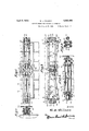
- Figure 1 is a top plan of the device in locked position with parts broken away;
- Figure 2 is a side elevation of construction shown in Figure 1
- Figure 3 is a View similar to Figure 1, showing a portion of the press in unlocked position;
- Figure 1 is a fragmentary section taken on line .li of Figure 2;
- Figure 5 is an end elevation of the locking mechanism in locked position
- Figure 6 is a fragmentary section on line 66 of Figure 3.
- Numeral 7 designates a press box having collapsible sides 8, 9, 10 and 11, hingedly connected to a base, not shown, in the usual manner.
- the ends 9 and 11 carry channel irons 12 having overlapping ends 13, with cut away portions let to receive dogs 15.
- Site 8 has secured thereto a bolster member 16 1930.
- a worm screw 26 operated by a wheel 27 is mounted on the front side 10.
- the worm screw 26 is mounted on a shaft 28, the shaft 28 being mounted in bearings 29 and the wheel 27 secured to one end of the shaft 28.
- Ratchet faced cams 30 are mounted on the face of the front side 10, said earns 30 being adapted to co-act with the worm screw 26.
- Links 31 are secured to the front outer edge of said cams 30 at 32, the opposite ends of links 31 being pivotally secured at 32 to levers 33, which in turn, are pivotally mounted on the face of the side 10 at 34, the levers 33 having shoulders 35 which contact with dogs 36.
- Hooks 39 are also formed integrally with the links 33 to receive the fingers 25, said dogs 36 being pivotally mounted at 37 adjacent the front corners of the box 7 and having lips 38 adapted to contact with the cut-away portions 13 of the side channel irons 12.
- the sides 8, 9, 10 and 11 of the box will be secured in place and the box 7 filled with cotton.
- the cotton will then be tramped until the usual bale is formed, and it is desired to remove the bale from the press.
- the wheel 27 is then rotated in a clockwise direction which causes the cams 30 to be rotated so that links 31 will be forced away 9 from each other, thus operating levers 33 to throw shoulders 35 out of contact with the dogs 36.
- the sides 8, 9, 10 and 11 are rotated into place, the dogs 36 are rotated until the lips 38 contact with the cut-away portions 14 of the channel irons 12 and rods 23'lifted and fingers 25 placed in engagement with the hooks 39, the wheel 27 having been rotated in the meantime until the hooks 39 are in position'to lightly engage the fingers 25.
- the wheel 25 is then rotated in a counter-clockwise direction until all the sides are securely locked in position ready to receive the cotton.
- ratchet faced cams connected to the last mentioned arms and screw-thread ed means to operate said ratchet faced cams.
- a cotton press having collapsible sides, arms pivotally secured to one side and extending from the opposite ends thereof along the adjacent. opposite sides, rods pivoted to the ends of said arms and having hooks formed on their free ends, levers pivoted on the remaining side and having lugs engaging said hooks, and means mounted on said remaining side for moving said levers to control the engagement of said lugs with said hooks.
- a cotton press having collapsible sides, arms pivotally secured to one of said sides and extending from the opposite ends thereof, rods pivoted to said arms and having hooks formed on their free ends, levers'pivoted on the remaining side and having lugs engaging said hooks, links pivotally connected to said levers, and means on said remaining side for moving said links to control the engagement of said lugs with said hooks.
- a cotton press having collapsible sides, jointed arms pivotally secured to the opposite ends of one of said sides and having hooks formed on the free ends of said arms, levers pivoted on the remaining side and having lugs adapted to be moved into and out of engagement with said hooks, and means on said remaining side for simultaneously moving said levers to control the engagement of the lugs with said hooks.
- a cotton press having. collapsible sides, jointed arms pivotally secured to the opposite ends of one of said sides'and having hooksformed on the free ends thereof, levers pivotally mounted on the remaining side and having lugs adapted to be moved into and out of engagement with said hooks, means mounted on said remaining side adjacent to said lever for retaining the adjacent-sides in closed position against said remaining sides, and means on said remaining sides for simultaneously operating said levers and said retaining means.
- a cotton press having collapsible sides, arms pivotallysecured to the opposite ends of one of said sides, rods pivotally connected to the ends of said arms and having hooks formed on the free ends thereof, linkage mechanisms mounted on said remaining side and having a part of each adapted to engage said hooks, and means rotatable about" an axis perpendicular to said remaining s1 de for simultaneously operatmg said mechamsms.
Description
April 5, 1932.
W. D. WILSON LOCKING MEANS FOR COTTON GIN PRESSES Filed April 25, 1930- 2 Sheets-Sheet l amen 01;
April 5, 1932. w D. WILSON LOCKING MEANS FOR COTTON GIN PRESSES Filed April 25, 1930 2 Sheets-Sheet 2 W- D. Wz'lrmzz I mm y n MM -w W M Wm, fl l m g 3 6N 3. T3 nwifi. ..r Mm NH Q mwflk |i I IN hm v mm -EE||IL F E m mm IJ i A HM k I H M =U \QM. .WAI
Patented Apr. 5, 1932 PATENT OFFICE WILLIAM DORSETT WILSON, OF MEMPHIS, TENNESSEE LOCKING MEANS FOR COTTON GIN PRESSES Application filed Aprl 25,
This invention relates to improvements in cotton presses; and more particularly, to locking and releasing means as applied to the press box.
The prime object is to provide means whereby the sides of the press box will be simultaneously released. As usually used, the press box will be filled with ginned cotton, and the same trumped so as to form a bale. In order to form the bale, it is, of
course, necessary to subject the cotton to intense pressure with the result that if any one of the sides of the press box is released before the others, a lop-sided bale will. result, since the sudden release of pressure on one side will force the cotton out on that side.
Numerous attempts have been made to solve this problem; but I believe my device is far simpler and less complicated than any heretofore placed on the market.
Another object is to provide the simplest adequate structure that will release the sides simultaneously, and at the same time, give adequate securing means.
Other objects will be disclosed in the spccification and drawings, forming a part of this application.
In the drawings:
Figure 1 is a top plan of the device in locked position with parts broken away;
Figure 2 is a side elevation of construction shown in Figure 1 Figure 3 is a View similar to Figure 1, showing a portion of the press in unlocked position;
Figure 1 is a fragmentary section taken on line .li of Figure 2;
Figure 5 is an end elevation of the locking mechanism in locked position; and
Figure 6 is a fragmentary section on line 66 of Figure 3.
Referring to the drawings in which like parts are designated with similar numerals:
Numeral 7 designates a press box having collapsible sides 8, 9, 10 and 11, hingedly connected to a base, not shown, in the usual manner. The ends 9 and 11 carry channel irons 12 having overlapping ends 13, with cut away portions let to receive dogs 15. Site 8 has secured thereto a bolster member 16 1930. Serial No. 147,3163.
having rotatably secured at its outer ends the dogs 15. Bolts 17, in addition to acting as securing members for the bolster plate 16 serve as stop members for the dogs 15. The dogs 15 have ears 18 which act as bearings for arms 19, which are secured in place by nuts 20 and 21. Loops 22 are formed in one end of the arms 19 and are connected to rods 23 by way of similar loops 2 1 which pass through loops 22. The ends of rods 23 are curved to form lingers 25. A worm screw 26 operated by a wheel 27 is mounted on the front side 10. The worm screw 26 is mounted on a shaft 28, the shaft 28 being mounted in bearings 29 and the wheel 27 secured to one end of the shaft 28.
Ratchet faced cams 30 are mounted on the face of the front side 10, said earns 30 being adapted to co-act with the worm screw 26. Links 31 are secured to the front outer edge of said cams 30 at 32, the opposite ends of links 31 being pivotally secured at 32 to levers 33, which in turn, are pivotally mounted on the face of the side 10 at 34, the levers 33 having shoulders 35 which contact with dogs 36. Hooks 39 are also formed integrally with the links 33 to receive the fingers 25, said dogs 36 being pivotally mounted at 37 adjacent the front corners of the box 7 and having lips 38 adapted to contact with the cut-away portions 13 of the side channel irons 12.
As actually operated, the sides 8, 9, 10 and 11 of the box will be secured in place and the box 7 filled with cotton. The cotton will then be tramped until the usual bale is formed, and it is desired to remove the bale from the press. The wheel 27 is then rotated in a clockwise direction which causes the cams 30 to be rotated so that links 31 will be forced away 9 from each other, thus operating levers 33 to throw shoulders 35 out of contact with the dogs 36.
Since there is an outward pressure exerted on all sides equally due to the pressure of the cotton, and since the securing means are released the sides, of course, will fly open. As soon as the retaining means for the sides 9, and 11 have been released, since the shoulders 85 have been rotated out of contact with the 109 dogs 36, the only securing means left for retaining the sides in locked position are the fin ers 25.
owever, as the levers 33 were rotated as stated, the hooks 39 were rotated out of engagement with the fingers 25 and since the rods 23 carrying the fingers 25 are connected loosely by loops Qt, they immediately dropped downwardly out of the way. Since all the securing means have now been released, the sides 8, 9, 10 and 11 simultaneously burst open so that the bale of cotton may be removed.
In order to lock the box, the sides 8, 9, 10 and 11 are rotated into place, the dogs 36 are rotated until the lips 38 contact with the cut-away portions 14 of the channel irons 12 and rods 23'lifted and fingers 25 placed in engagement with the hooks 39, the wheel 27 having been rotated in the meantime until the hooks 39 are in position'to lightly engage the fingers 25. The wheel 25 is then rotated in a counter-clockwise direction until all the sides are securely locked in position ready to receive the cotton.
It is obvious that I have produced a structure which is simple but extremely efiicient to accomplish my aims.
WVhat I claim is:
1. Ina press box for cotton having collapsible sides consisting of front, back, and end walls, arms secured to the back side and extending therefrom along the adjacent end members, dogs pivotally mounted on the front side for holding the end members in closed position, links pivotally mounted on the front side having shoulders to contact with said dogs and fingers to contact with said arms, other arms connected to said links and extending therefrom. ratchet faced cams connected to the last mentioned arms and screw-thread ed means to operate said ratchet faced cams.
2. In a cotton press having collapsible sides, arms pivotally secured to one side and extending from the opposite ends thereof along the adjacent. opposite sides, rods pivoted to the ends of said arms and having hooks formed on their free ends, levers pivoted on the remaining side and having lugs engaging said hooks, and means mounted on said remaining side for moving said levers to control the engagement of said lugs with said hooks.
3. In a cotton press having collapsible sides, arms pivotally secured to one of said sides and extending from the opposite ends thereof, rods pivoted to said arms and having hooks formed on their free ends, levers'pivoted on the remaining side and having lugs engaging said hooks, links pivotally connected to said levers, and means on said remaining side for moving said links to control the engagement of said lugs with said hooks.
4. In a cotton press having collapsible sides, arms pivotally secured to the opposite ends of one of said sides, rods pivoted to said arms and having hooks formed on their free ends, levers pivoted on the remaining side and having lugs engageable with said hooks, and means for simultaneously moving said levers to eflect engagement thereof with said hooks. V
5. In a cotton press having collapsible sides, jointed arms pivotally secured to the opposite ends of one of said sides and having hooks formed on the free ends of said arms, levers pivoted on the remaining side and having lugs adapted to be moved into and out of engagement with said hooks, and means on said remaining side for simultaneously moving said levers to control the engagement of the lugs with said hooks.
6. In a cotton press having. collapsible sides, jointed arms pivotally secured to the opposite ends of one of said sides'and having hooksformed on the free ends thereof, levers pivotally mounted on the remaining side and having lugs adapted to be moved into and out of engagement with said hooks, means mounted on said remaining side adjacent to said lever for retaining the adjacent-sides in closed position against said remaining sides, and means on said remaining sides for simultaneously operating said levers and said retaining means.
7. In a cotton press having collapsible sides, arms pivotallysecured to the opposite ends of one of said sides, rods pivotally connected to the ends of said arms and having hooks formed on the free ends thereof, linkage mechanisms mounted on said remaining side and having a part of each adapted to engage said hooks, and means rotatable about" an axis perpendicular to said remaining s1 de for simultaneously operatmg said mechamsms.
sides, arms pivotally secured to one side thereof and extending along the opposite ends of the adjacent sides beyond the remaining side, locking levers pivotally mounted on the remaining side for locking engagement with said arms, and means rotatable. on said remaining side about an axis perpendicular thereto for simultaneously operating said levers.
In testimony whereof I aflix my signature.
WILLIAM DORSETT WILSON.
8. In a cotton press having collapsible
Priority Applications (1)
| Application Number | Priority Date | Filing Date | Title |
|---|---|---|---|
| US447316A US1852495A (en) | 1930-04-25 | 1930-04-25 | Locking means for cotton gin presses |
Applications Claiming Priority (1)
| Application Number | Priority Date | Filing Date | Title |
|---|---|---|---|
| US447316A US1852495A (en) | 1930-04-25 | 1930-04-25 | Locking means for cotton gin presses |
Publications (1)
| Publication Number | Publication Date |
|---|---|
| US1852495A true US1852495A (en) | 1932-04-05 |
Family
ID=23775875
Family Applications (1)
| Application Number | Title | Priority Date | Filing Date |
|---|---|---|---|
| US447316A Expired - Lifetime US1852495A (en) | 1930-04-25 | 1930-04-25 | Locking means for cotton gin presses |
Country Status (1)
| Country | Link |
|---|---|
| US (1) | US1852495A (en) |
Cited By (1)
| Publication number | Priority date | Publication date | Assignee | Title |
|---|---|---|---|---|
| US3033103A (en) * | 1956-10-03 | 1962-05-08 | Saito Tomizo | Packing apparatus for staple fiber, raw cotton and the like |
-
1930
- 1930-04-25 US US447316A patent/US1852495A/en not_active Expired - Lifetime
Cited By (1)
| Publication number | Priority date | Publication date | Assignee | Title |
|---|---|---|---|---|
| US3033103A (en) * | 1956-10-03 | 1962-05-08 | Saito Tomizo | Packing apparatus for staple fiber, raw cotton and the like |
Similar Documents
| Publication | Publication Date | Title |
|---|---|---|
| US1852495A (en) | Locking means for cotton gin presses | |
| DE832412C (en) | Door lock for motor vehicles | |
| US3167343A (en) | Erection clamp | |
| US1769128A (en) | Grate-bar spacer for thrashers | |
| DE2905893C2 (en) | Braking device for mobile containers | |
| DE908608C (en) | Coke oven door | |
| US205056A (en) | Improvement in baling-presses | |
| US171560A (en) | Improvement in cotton-bale-band tighteners | |
| AT65657B (en) | Adjustable nut wrench. | |
| DE2248093A1 (en) | SAFETY DEVICE ON SPINTERS | |
| DE506743C (en) | Mechanical type lever drive for typewriters | |
| US1230200A (en) | Cloth-bolt press. | |
| DE661369C (en) | Device for the dust-free shoveling of bulk goods, in particular garbage, from a vessel into a collecting container with a tilting frame provided with a lid closure | |
| DE626841C (en) | Nutcracker | |
| DE720208C (en) | Unloading gear, especially for dump trucks | |
| DE516942C (en) | Children's toys with propellers | |
| DE958880C (en) | Coupling for calculating machines, especially four-species calculating machines | |
| DE137444C (en) | ||
| DE339781C (en) | Door security with alarm device | |
| DE554133C (en) | Pressure nut | |
| AT82317B (en) | Lock for sliding railroad car doors. | |
| DE834169C (en) | Lifting device for spring-loaded valves | |
| DE174827C (en) | ||
| DE701011C (en) | Wafer baking machine, the hinged lid of which is secured in its closed position by a locking device | |
| US593753A (en) | Box-fastener |