US1851171A - Stapler mechanism clutch - Google Patents
Stapler mechanism clutch Download PDFInfo
- Publication number
- US1851171A US1851171A US424307A US42430730A US1851171A US 1851171 A US1851171 A US 1851171A US 424307 A US424307 A US 424307A US 42430730 A US42430730 A US 42430730A US 1851171 A US1851171 A US 1851171A
- Authority
- US
- United States
- Prior art keywords
- clutch
- machine
- rod
- cam
- latch
- Prior art date
- Legal status (The legal status is an assumption and is not a legal conclusion. Google has not performed a legal analysis and makes no representation as to the accuracy of the status listed.)
- Expired - Lifetime
Links
- 230000000994 depressogenic effect Effects 0.000 description 2
- 238000013459 approach Methods 0.000 description 1
- 238000010276 construction Methods 0.000 description 1
- 238000012986 modification Methods 0.000 description 1
- 230000004048 modification Effects 0.000 description 1
Images
Classifications
-
- A—HUMAN NECESSITIES
- A43—FOOTWEAR
- A43D—MACHINES, TOOLS, EQUIPMENT OR METHODS FOR MANUFACTURING OR REPAIRING FOOTWEAR
- A43D71/00—Elements of nailing machines; Nail-feeding devices
- A43D71/02—Driving mechanisms for moving the horn; Nail-cutting apparatus connected with the horn
Definitions
- My invention relates to machineryused in themanufacture' of shoes and more particu# larly to a machinel tok be used for driving fasteners through the Vsole of a shoe and parts in Patent Number 1,016,930, issued February 18, 1912 toW. H. Borden.
- a machine of L this type is actuated by the depression of a,
- the loperator f must release the treadleand shift theshoe after the driving of ⁇ each staple and before the driving of the succeeding staple.
- the ladjustment might be suchthaty the treadlefcouldbe depressed and if, theV n taken on the line 2-2 of Figure 1.
- a particular object of my present invention is to provide a. positive clutch release vmeans that will function in every cycleof the operations of the machine at Ythe proper time without regard to how r4far thetreadle is depressed and without requiring special'skill or attention. in the adjustment or the ⁇ vas sembling or setting 4up ofeach machine.V
- Figure 2 is a sectional view kofthe same Figure 8 is a similar view of some of the parts in the lower portion Aof Figure 1, but shownin a different position. y
- yFigl'ires 4 and 51 are diagrammatic views fof the relation ⁇ between one ⁇ of theclutch operating cams and the interengaging elements of my invention associated therewith.
- Thefraine of thek machine is indicated at 1. Near the top thereof is journalled the ⁇ mainshaft 2-which mounts a loose pulley 3 adapted to be driven by a rbelt from amotor ⁇ or counter-shafting in the conventional i manner. ⁇ v
- a clutch disk having ahub 4 isfiXed on the shaft 2and is adapted to engage the rim of the pulley 3 when the latter is moved toward
- the collar 5 is freely mounted on the disk; y the ⁇ shaft 2 ⁇ and engages both the pulley hub and alyoke 6 which is movable transversely ofthe shaft.4k
- the interengaging surfaces of as f Y'the collar 5 and'yoke 6 are in a plane between the horizontal and the vertical naxes of the machine as indicated at 7 whereby downward movementV of the yoke thrusts the collar 5 to j the 'i left therebymoving the clutch disk into engagement with the pulley 3 whereby shaft 2 is rotated to operate the machine.
- Yoke 6 is operated by pull i'od 10.
- a treadle 1 is fulcrumed at 12 on a bracket 13 mounted on the base of the frame 1 and a bell crank latch member 14 is pivoted at 15 to the treadle 11 and has a hook-like upper end piovided with a downwardly-facing element 16.
- a cooperating upwardly-facing element 17 is mounted on the lower end of pull rod 10. The rod 25 holds the latch 14 in substantially vertical position until the rod is moved as hereinafter explained.
- a cam 18 Fixedly mounted on the shaft 2 is a cam 18. Attached to the side of the frame 1 is a bracket 19 journalling a pin 20. F ixedly mounted on the ends of pin 2O are' rarm 21 having a roller 22 engaging the cam 18, and 4arm 23 pivoted to rod 25 at 24.
- the rod 25 is pivoted to ythe lower end of the bell crank latch member 14 at 26.
- arm 21 is pushed outwardly on the pin 2O and arm 23 consequently is pushed upwardly lifting rod 25 and turning latch 14 on pivot 15 so that the latch disengages pull rod 10, permitting spring 28, actingon bracket 29 seated on frame 1 and collar 30 on rod 10, to push rod 10 upwardly and disengage the clutch when the low portion of cam 8 is over roller 50.
- a link 31 extends upwardly from treadle 11 and through spring 32 operates a lever 33 to raise the shoe'support 34 to clamp the rshoe between anvil 35 and the stapler throat 36 in the usual manner.
- cam 8 is in rposition to hold the clutch engaged.
- the projecting portion of cam 18 has rotated counter clockwise to the position Where it engages the roller 22 and the latch release has been effected and the dwell of the cam 8 is engaging the roller 50 on the end of rod 10.
- cam 8 approaches the position shown on the left side of Figure 4, the rod shoots up and the clutch is released.
- a clutch In a machine of the class described, a clutch, a clutch operating mechanism, a clutch driven shaft, cams rotated thereby, a manually operated clutch engaging device, means releasing said clutch from said device actuated by one of said cams, the other of said cams holding said clutch engaged after the starting of said machine until said release means has been actuated by said first cam.
- clutch including interengaging rotating disks and yielding means normally thrusting said disks apart, a clutch actuating mechanism including a pull rod, and collars forced together by movement of said rod to positively move said disks into engagement, an operating lever, interengaging hook-like elements on said rod and lever respectively whereby said rrod is moved by said lever, and a rotatable member disengaging said elements after predetermined opei'atioii of the machine.
- an operating shaft a clutch for driving the same
- a clutch actuating mechanism including a vertically disposed pull rod having an upwardlyfacing element, a treadle, a latch ivoted between its'ends on said treadle wit its upper end extending adjacent to said rod and having a downwardly-facing element engaging said rod element, and a means driven by said shaft and connected to the lower end of said latch for disengaging said elements after movement of said rod by said treadle.
- an operating shaft a clutch for driving the same
- a clutch actuating mechanism including avertically disposed pull rod having an upwardlyfacing element, a treadle, a ylatch pivoted between its ends on said treadle with its upper end extending adjacent to said rod and having a downwardly-facing element engaging said rod element, a means driven by said shaft and connected to thelower end of said latch for disengaging said elements after movement of said rod by said treadle, said means returning said latch to position where said elements are engaged when said'treadle and rod are raised.
- a frame a treadle fulcrumed on said frame.
- a latch pivoted on said treadle, a cam, a member operated by said cam, said member being connected to said latch and adapted to move said latch on its pivot after a cycle of operations of the machine initiated by movement of saidtreadle, and a clutch actuating member adapted to be engaged by said latch after predetermined movement of said cam.k
- a frame a lever fulcrumed on said frame, a clutch actuating mechanism including a shaft, a cam driven thereby, a pull rod, a lateral projection on saidk rod, a bell crank latch pivoted on saidlever and adapted to engage said projection, and means engaged by said cam and operatively connected to said latch adapted 'to disengagesaid latch and projection after, movement of said latch by ⁇ said Y lever and yduring a cycle ofoperations of the machine.
- a structure as specied in claim 2 which also includes means holding said clutch disks engaged throughout a cycle of operations of the machine irrespective of the disengagement of saidhook-like elements.
- Astructure as specied in claim 2 which also includes means holding said rod in clutch engaging position throughout a cycle of operations of the machine irrespectivemf the disengagement of said hook-like elements.
Landscapes
- Portable Nailing Machines And Staplers (AREA)
Description
MalCh 29, 1932- J. J. GOELLNER STAPLER MECHAMSM CLUTCH Filed Jan. 29,1930
Patented Mar.l 2,9, 1932` PATENT OFFICE JOSEPH J. GOELLER, O1? ST. LOUIS, MISSOURI, ASSIGNOR 'TO 'LANDIS IVIACHINECOLMI-V PANY, F LOUIS, MISSOURI, A CORPORATION MISSOURI STAPLER MncHANIsM CLUTCH Applicatomle'd January 29, 1930.' Serial 110.424,30?.
My invention relates to machineryused in themanufacture' of shoes and more particu# larly to a machinel tok be used for driving fasteners through the Vsole of a shoe and parts in Patent Number 1,016,930, issued February 18, 1912 toW. H. Borden. A machine of L this type is actuated by the depression of a,
treadle for the driving ofeach staple. The depression of thetreadle by the'opcrators f foot causes a clutch between the machine l treadle is not'held down. Y
and the driving mechanism to function, which, clutch is automatically disengaged at the end of each driving operation In running such a machine,the loperator f must release the treadleand shift theshoe after the driving of `each staple and before the driving of the succeeding staple.
If the utmost skill is not used,.more than one Vstaple 'may be driven at thesame placevv orthe staples may not be spaced properly.I
` It is the general object of my present invention to provide such a machine with a device that will automatically release the clutch 'at the proper time during. each cycle of operations of the machine.` Y
Mypresent invention, though of different construction, has'all of the advantages set Vforth in my copending application led September 11, 1929, SerialNumber391,790` land in addition has certain advantageous features not present in the structureof my,`
copending application.
Now, lin the VAstructure of 'my copending application, dependence is 'placed' upon then strength of a spring to keep the" latch inen-l gaged position andv rather exact relative acljustment of the various meinbersis necessary 'to prevent the clutch fromreleasing too soon.
or too late.V It would bepossible in this structure, if the adjustment were not correct, for
the clutch releasing mechanism to,}g 'rev,enty the rclutch from being engaged 'at allor, on v`the other hand, the ladjustment might be suchthaty the treadlefcouldbe depressed and if, theV n taken on the line 2-2 of Figure 1.
. the machine continue to operate without the clutch being released aty all.
A particular object of my present invention is to provide a. positive clutch release vmeans that will function in every cycleof the operations of the machine at Ythe proper time without regard to how r4far thetreadle is depressed and without requiring special'skill or attention. in the adjustment or the `vas sembling or setting 4up ofeach machine.V
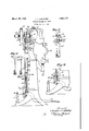
' Iny the accompanying drawings which illustrate a selected embodiment cfmy inventionf Figure 1 is aside elevationk of a stapler showing my clutchV engaging and releasingl apparatus. n y
Figure 2 is a sectional view kofthe same Figure 8 is a similar view of some of the parts in the lower portion Aof Figure 1, but shownin a different position. y
yFigl'ires 4 and 51 are diagrammatic views fof the relation `between one` of theclutch operating cams and the interengaging elements of my invention associated therewith. Thefraine of thek machine is indicated at 1. Near the top thereof is journalled the` mainshaft 2-which mounts a loose pulley 3 adapted to be driven by a rbelt from amotor` or counter-shafting in the conventional i manner.` v
A clutch disk having ahub 4 isfiXed on the shaft 2and is adapted to engage the rim of the pulley 3 when the latter is moved toward The collar 5 is freely mounted on the disk; y the `shaft 2`and engages both the pulley hub and alyoke 6 which is movable transversely ofthe shaft.4k The interengaging surfaces of as f Y'the collar 5 and'yoke 6 are in a plane between the horizontal and the vertical naxes of the machine as indicated at 7 whereby downward movementV of the yoke thrusts the collar 5 to j the 'i left therebymoving the clutch disk into engagement with the pulley 3 whereby shaft 2 is rotated to operate the machine. fA cam 8 on shaft 2 engages a cam roller 50 von yoke 6 as soon as the shaft `starts. to rotate and. holds the yoke down until the rotation of the shaft is completed when the rollerv is freed fifornthe cam yand yoke may rise, thereby.
releasing the clutch disk from the pulley.
Yoke 6 is operated by pull i'od 10. A treadle 1 is fulcrumed at 12 on a bracket 13 mounted on the base of the frame 1 and a bell crank latch member 14 is pivoted at 15 to the treadle 11 and has a hook-like upper end piovided with a downwardly-facing element 16. A cooperating upwardly-facing element 17 is mounted on the lower end of pull rod 10. The rod 25 holds the latch 14 in substantially vertical position until the rod is moved as hereinafter explained.
Fixedly mounted on the shaft 2 is a cam 18. Attached to the side of the frame 1 is a bracket 19 journalling a pin 20. F ixedly mounted on the ends of pin 2O are' rarm 21 having a roller 22 engaging the cam 18, and 4arm 23 pivoted to rod 25 at 24.
The rod 25 is pivoted to ythe lower end of the bell crank latch member 14 at 26. Thus, when the projecting portion of cam 18 engages roller 22, arm 21 is pushed outwardly on the pin 2O and arm 23 consequently is pushed upwardly lifting rod 25 and turning latch 14 on pivot 15 so that the latch disengages pull rod 10, permitting spring 28, actingon bracket 29 seated on frame 1 and collar 30 on rod 10, to push rod 10 upwardly and disengage the clutch when the low portion of cam 8 is over roller 50.
A link 31 extends upwardly from treadle 11 and through spring 32 operates a lever 33 to raise the shoe'support 34 to clamp the rshoe between anvil 35 and the stapler throat 36 in the usual manner.
Operation: When the operator steps on the treadle 11 and depresses the same sufficiently to cause the elements 16 and 17 to engage one another and the rod 1() and yoke 6 to be pulled downwardly, the clutch is engaged and the machine starts its cycle of operations.
The two cams `8 and 18 are so placed on the shaft 2 that by the time the Ylatch 14 and pull Vrod 10 are released by cam 18, cam 8 is in rposition to hold the clutch engaged. Thus, when the staple has been driven into the shoe, the projecting portion of cam 18 has rotated counter clockwise to the position Where it engages the roller 22 and the latch release has been effected and the dwell of the cam 8 is engaging the roller 50 on the end of rod 10. As cam 8 approaches the position shown on the left side of Figure 4, the rod shoots up and the clutch is released. The projecting portion of the cam 18 by the end of this operation has passed beyond roller 22, a brake (not shown) has stopped the movement of shaft 2 and the arm 22 has moved inwardly again, returning the latchA other until the portion 16 is above portion 17 and the machine is again ready for operation.
Obviously, many of the details of my invention may be modified without departing from the spirit of my invention and I contemplate the exclusive use of all suoli modifications as come within the scope of my claims.
I claim:
1. In a machine of the class described, a clutch, a clutch operating mechanism, a clutch driven shaft, cams rotated thereby, a manually operated clutch engaging device, means releasing said clutch from said device actuated by one of said cams, the other of said cams holding said clutch engaged after the starting of said machine until said release means has been actuated by said first cam.
2. In a. machine of the class described, a
clutch including interengaging rotating disks and yielding means normally thrusting said disks apart, a clutch actuating mechanism including a pull rod, and collars forced together by movement of said rod to positively move said disks into engagement, an operating lever, interengaging hook-like elements on said rod and lever respectively whereby said rrod is moved by said lever, and a rotatable member disengaging said elements after predetermined opei'atioii of the machine.
3. In a machine of the class described, an operating shaft, a clutch for driving the same, a clutch actuating mechanism including a vertically disposed pull rod having an upwardlyfacing element, a treadle, a latch ivoted between its'ends on said treadle wit its upper end extending adjacent to said rod and having a downwardly-facing element engaging said rod element, and a means driven by said shaft and connected to the lower end of said latch for disengaging said elements after movement of said rod by said treadle.
4. In a machine of theclass described, an operating shaft, a clutch for driving the same, a clutch actuating mechanism including avertically disposed pull rod having an upwardlyfacing element, a treadle, a ylatch pivoted between its ends on said treadle with its upper end extending adjacent to said rod and having a downwardly-facing element engaging said rod element, a means driven by said shaft and connected to thelower end of said latch for disengaging said elements after movement of said rod by said treadle, said means returning said latch to position where said elements are engaged when said'treadle and rod are raised.
5. In a machine of the class described, a frame, a treadle fulcrumed on said frame. a latch pivoted on said treadle, a cam, a member operated by said cam, said member being connected to said latch and adapted to move said latch on its pivot after a cycle of operations of the machine initiated by movement of saidtreadle, and a clutch actuating member adapted to be engaged by said latch after predetermined movement of said cam.k
6. In a machine ofthe class described, a frame, a lever fulcrumed on said frame, a clutch actuating mechanism including a shaft, a cam driven thereby, a pull rod, a lateral projection on saidk rod, a bell crank latch pivoted on saidlever and adapted to engage said projection, and means engaged by said cam and operatively connected to said latch adapted 'to disengagesaid latch and projection after, movement of said latch by` said Y lever and yduring a cycle ofoperations of the machine. l.
7.' A. structure as specified in claim 2 which also includes 'means automatically placing said hooklike elements in position to be interengaged again after a cycle of operations of the machine is completed.`
8. A structure as specied in claim 2 which also includes means holding said clutch disks engaged throughout a cycle of operations of the machine irrespective of the disengagement of saidhook-like elements.
9. Astructure as specied in claim 2 which also includes means holding said rod in clutch engaging position throughout a cycle of operations of the machine irrespectivemf the disengagement of said hook-like elements.
Y In testimony whereof I hereunto aiiix ,my signature this 26th day of December, 1929.
' Y JOSEPH J. GOELLNER.
Priority Applications (1)
| Application Number | Priority Date | Filing Date | Title |
|---|---|---|---|
| US424307A US1851171A (en) | 1930-01-29 | 1930-01-29 | Stapler mechanism clutch |
Applications Claiming Priority (1)
| Application Number | Priority Date | Filing Date | Title |
|---|---|---|---|
| US424307A US1851171A (en) | 1930-01-29 | 1930-01-29 | Stapler mechanism clutch |
Publications (1)
| Publication Number | Publication Date |
|---|---|
| US1851171A true US1851171A (en) | 1932-03-29 |
Family
ID=23682168
Family Applications (1)
| Application Number | Title | Priority Date | Filing Date |
|---|---|---|---|
| US424307A Expired - Lifetime US1851171A (en) | 1930-01-29 | 1930-01-29 | Stapler mechanism clutch |
Country Status (1)
| Country | Link |
|---|---|
| US (1) | US1851171A (en) |
Cited By (2)
| Publication number | Priority date | Publication date | Assignee | Title |
|---|---|---|---|---|
| US2733799A (en) * | 1956-02-07 | williams | ||
| US2907424A (en) * | 1951-11-09 | 1959-10-06 | United Shoe Machinery Corp | Clutch control mechanisms |
-
1930
- 1930-01-29 US US424307A patent/US1851171A/en not_active Expired - Lifetime
Cited By (2)
| Publication number | Priority date | Publication date | Assignee | Title |
|---|---|---|---|---|
| US2733799A (en) * | 1956-02-07 | williams | ||
| US2907424A (en) * | 1951-11-09 | 1959-10-06 | United Shoe Machinery Corp | Clutch control mechanisms |
Similar Documents
| Publication | Publication Date | Title |
|---|---|---|
| US1851171A (en) | Stapler mechanism clutch | |
| US2271359A (en) | Safety control | |
| US2442574A (en) | Clutch control for duplicating machines | |
| US2158484A (en) | Sewing machine stop motion | |
| US1851170A (en) | Clutch control for stapling machines | |
| US2077531A (en) | Thread cutting device for buttonhole and similar sewing machines | |
| US1538930A (en) | Starting and stopping mechanism | |
| US1799996A (en) | Pulling-over machine | |
| US1921277A (en) | Shoe stitcher | |
| US2207297A (en) | Safety device for kick presses | |
| US1681610A (en) | Machine for tying wire ties | |
| US2122594A (en) | Clutch and operating mechanism therefor | |
| US2005439A (en) | Basket making machine and method | |
| US2338204A (en) | Machine for equipping box parts with fastening means | |
| US2008621A (en) | Automatic pressure foot adjusting device | |
| US1682770A (en) | Basket-making machine | |
| GB399942A (en) | Improvements in clutch mechanism for power operated machines | |
| US1604598A (en) | Clutch mechanism for power presses | |
| US2315041A (en) | Perforating machine provided with clutch control mechanisms | |
| US1532634A (en) | Stopping and starting mechanism for shoe-stitching or other machines | |
| US2421639A (en) | Machine for forming and reinforcing cutouts | |
| US2320857A (en) | Pressing machine | |
| US2258936A (en) | Broom machine | |
| US2015033A (en) | Attaching machine | |
| US2007579A (en) | Hamper lid fastening mechanism |